
Cooling fan engineering FAQ
Answers that start at the operating point.
Practical selection and validation questions collected from the engineering problems behind our guides and application articles. Use them to structure your next cooling design review.
12 questions
No matching answer. Try a broader engineering term or send the installed operating conditions for review.
Selection and airflow
The installed air path decides the result.
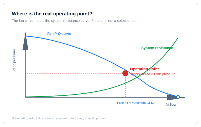
Can I select a fan from maximum CFM?
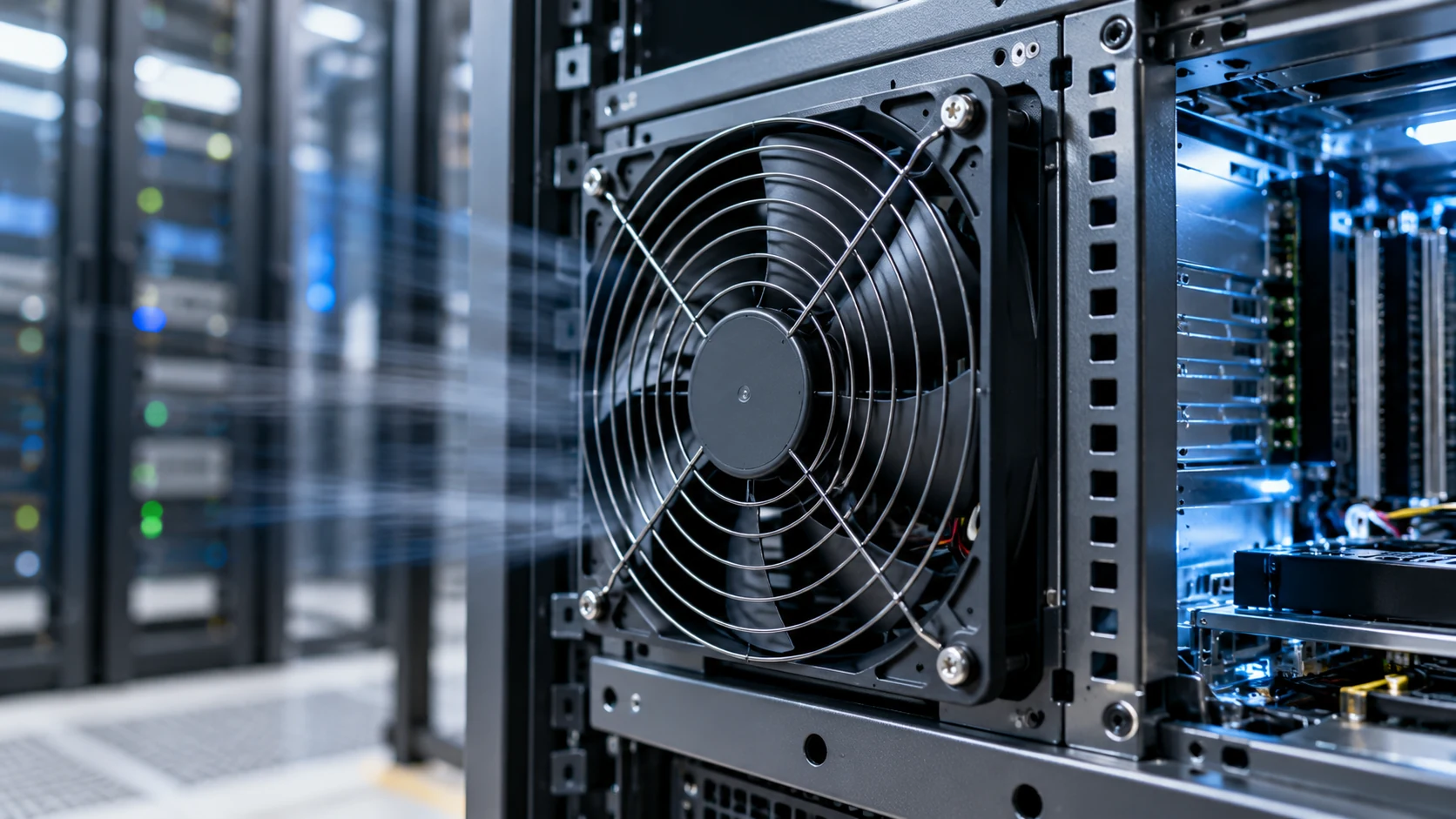
No. Maximum CFM is measured at a free-air endpoint. The actual operating point is where the fan P-Q curve intersects the resistance curve of the enclosure, filter, grille, heat sink and ducts. Specify airflow at a stated pressure, then validate it in the assembly.
| What to state | Why it matters |
|---|---|
| Airflow at a stated static pressure | Defines a real duty point on the P-Q curve |
| Installed path data (filter, grille, ducts, heat sink) | Fixes the system resistance curve |
| In-assembly measurement plan | Confirms the point in the real product, not in free air |
When is an axial fan the wrong choice?
Axial and centrifugal fans solve different pressure-path problems. A compact turn, narrow outlet, dense filter or higher resistance can favor a blower. Compare the installed P-Q curves before choosing by frame shape or catalogue CFM.
Do two fans in parallel double airflow?
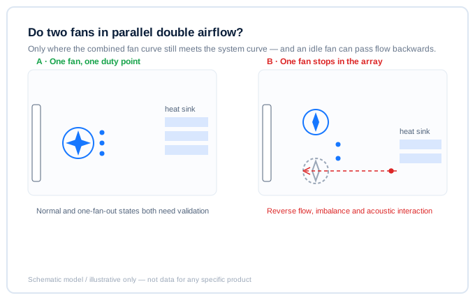
Not automatically. The combined fan curve must still meet the system curve. Parallel fans can also introduce reverse flow through an idle fan, distribution imbalance and acoustic interaction. Validate normal and one-fan-out states in the actual path.
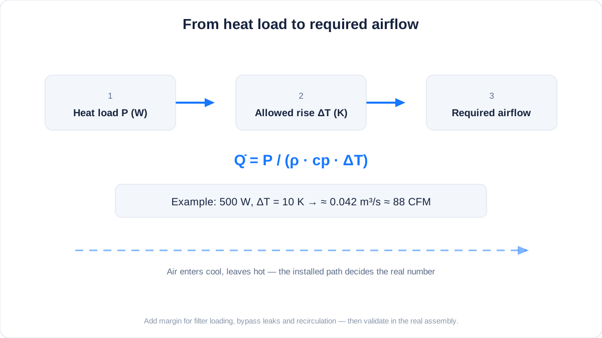
How do I estimate required airflow from heat load?
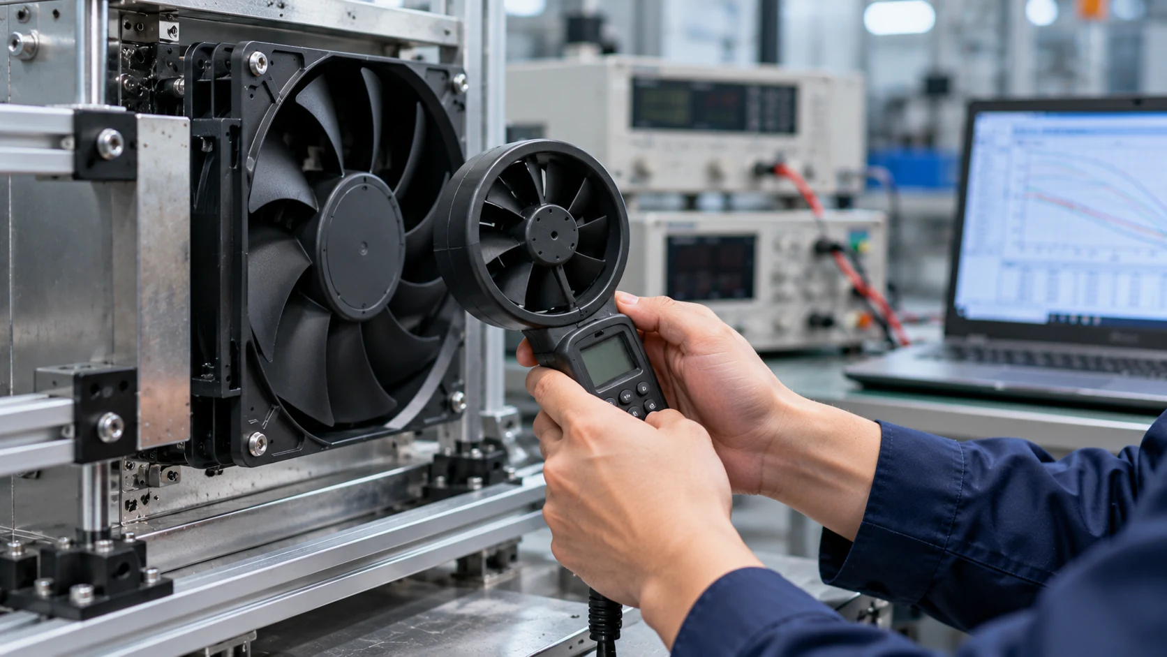
Start from the energy balance: Q = P / (ρ · cp · ΔT). For air near sea level, 500 W with an allowed 10 K rise needs about 0.042 m³/s (≈ 88 CFM). That result is a theoretical minimum — it assumes the air sweeps the heat source and leaves at exactly ΔT. Add margin for bypass leaks, filter loading and recirculation, then confirm the point in the real assembly instead of trusting the calculation alone.
Control and diagnostics
RPM is evidence, not proof of cooling.
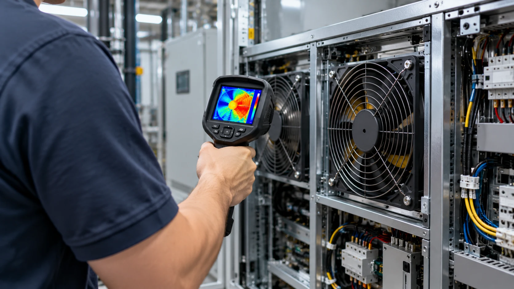
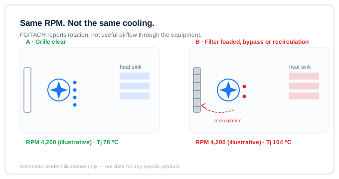
Does normal RPM prove that enough air reaches the heat source?
No. FG/TACH reports rotation, not useful airflow through the equipment. A blocked grille, loaded filter, bypass route or recirculation path can leave RPM normal while component temperature rises. Record command, speed, supply voltage, pressure or flow and temperatures together.
| Signal | What it actually tells you |
|---|---|
| PWM duty | What the controller asked for |
| FG / TACH speed | Shaft rotation only — not delivered airflow |
| Supply voltage | Operating margin at the connector |
| Pressure or flow | Actual delivery through the installed path |
| Component temperatures | The outcome the fan is there to produce |
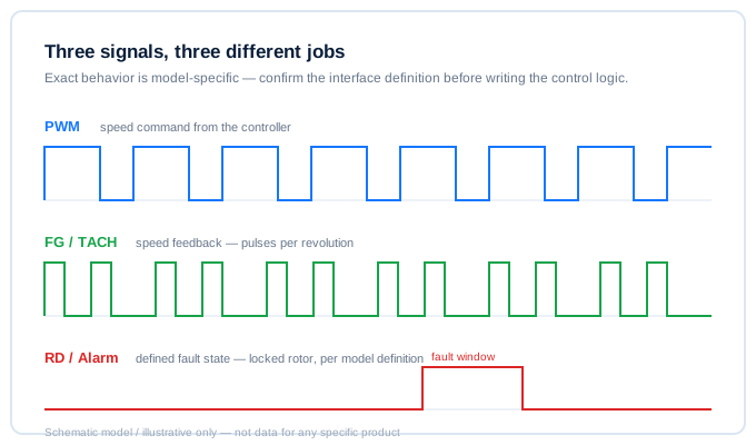
What should PWM, FG and RD signals each be used for?
PWM is normally a speed command; FG/TACH gives speed feedback; RD or locked-rotor output indicates a defined fault state. Their exact behavior is model-specific. They should support, not replace, thermal and installed-airflow verification.
Why can a fan control loop hunt or create audible noise?
Sensor location, thermal lag, hysteresis, minimum stable speed, pressure-path changes and structural resonance can interact. First check the air path and measured response; do not solve a control or resonance issue only by raising fan speed.
How should an N+1 fan array be validated?
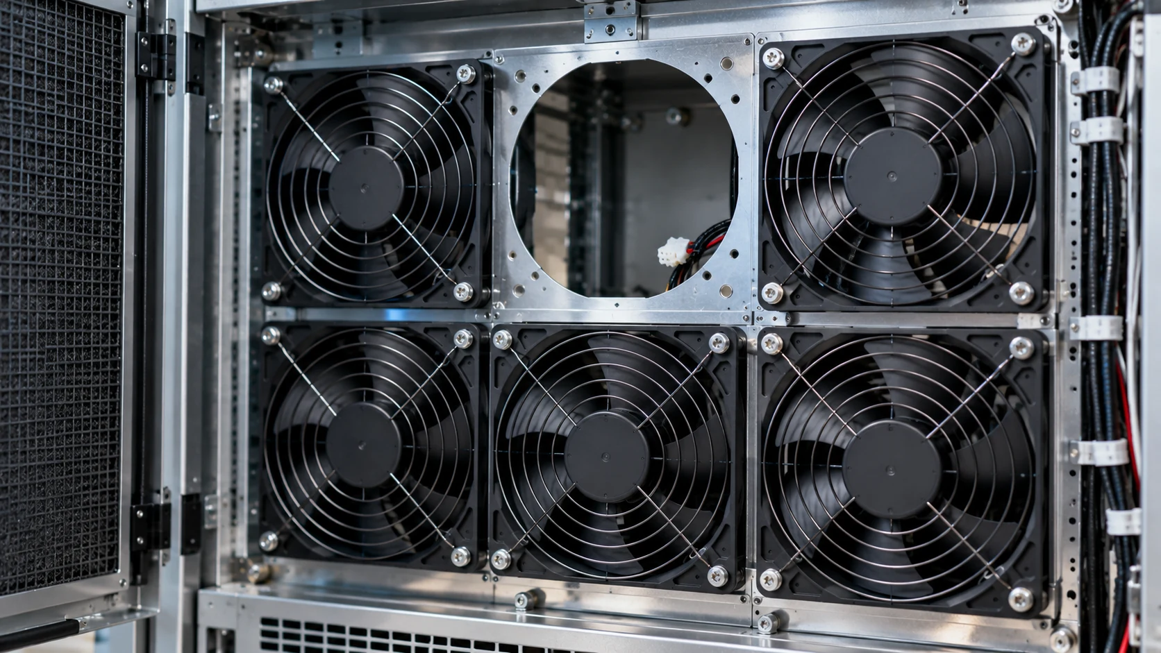
Validate both states, not just the healthy one. With all fans running, record per-fan RPM and current plus the array total flow or pressure. Then switch one fan off and repeat: verify the remaining fans hold the required flow, no reverse flow develops through the idle fan, and the RD/FG alarms report correctly. Repeat at worst-case filter loading and ambient. An N+1 array that has only ever been tested intact is not validated.
Reliability and environment
Define the actual service condition.
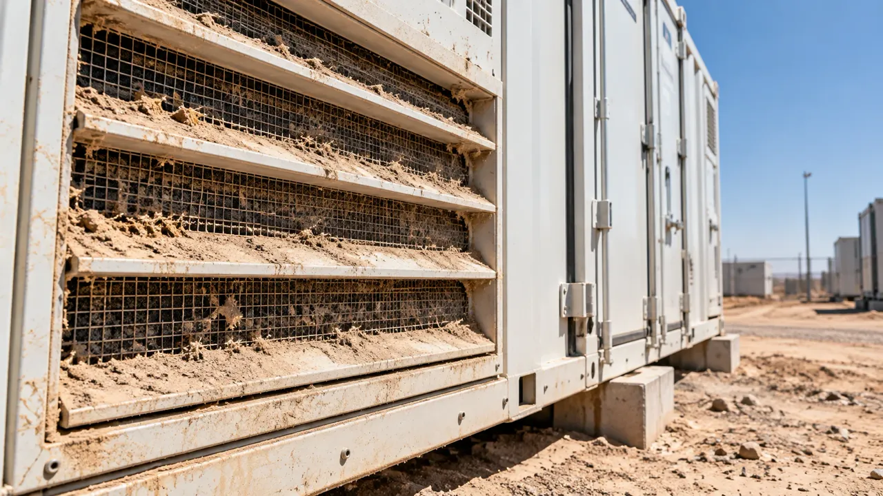
Should a dirty-filter condition be included in fan validation?
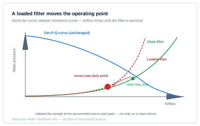
Include it when a filter is part of the product's credible service condition. A loaded filter changes resistance and moves the operating point. The target is not one universal multiplier; it is a documented worst-case path for the specific product.
How should high temperature affect a fan decision?
Use the application ambient and duty cycle, not room temperature. Temperature affects electronics, bearing lubrication, noise, current and service life. Confirm the intended environmental range and validate the sample at representative conditions.
Does an IP rating describe the whole cooling design?
No. The enclosure, air inlet, filter, cable exit, drain path and maintenance process all affect ingress performance. Treat the fan as one component in the assembled environmental design.
How does altitude affect fan selection?
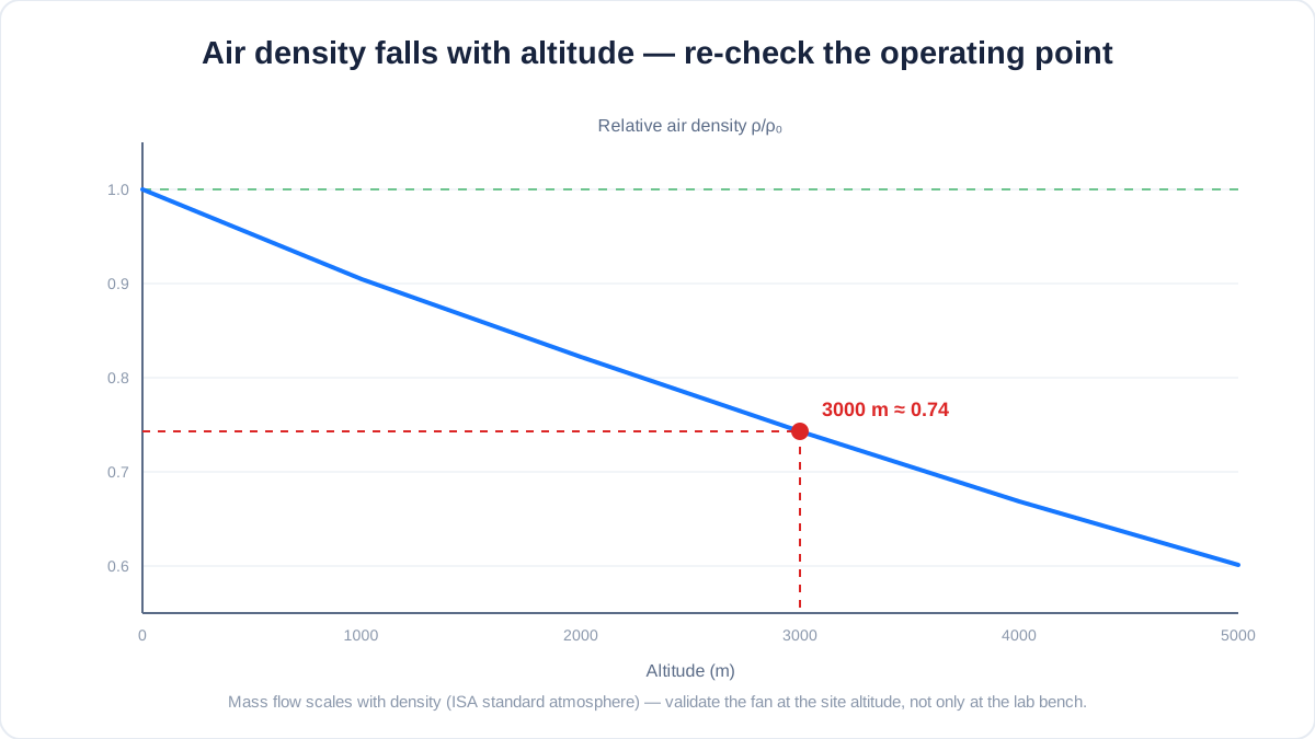
Air density falls with altitude: about 0.90 at 1000 m, 0.82 at 2000 m and 0.74 at 3000 m (ISA). Mass flow scales with density, so the same fan delivers less cooling mass flow at an elevated site, and the lower pressure shifts the operating point along the P-Q curve. State the site altitude in the RFQ and validate the sample at representative density — an altitude chamber or a derated bench test — before freezing the design.
| What to state | Why it matters |
|---|---|
| Site altitude (m) | Sets the density ratio applied to the fan curve |
| Ambient temperature at site | High ambient and low density compound on electronics and bearings |
| Filter condition at worst case | A loaded filter plus thin air is the real worst case |
| Duty cycle at altitude | Peak versus continuous duty changes the thermal check |
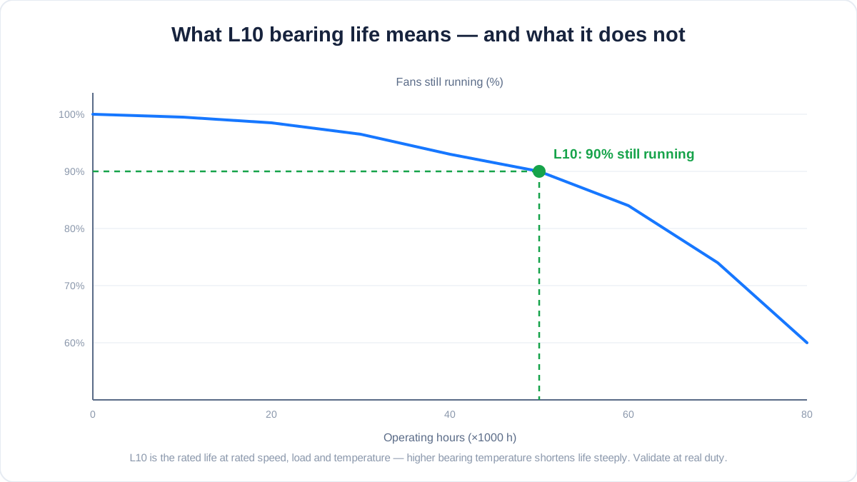
What does L10 bearing life actually mean?
L10 is the life by which 90% of an identical batch of fans is still running, at rated speed, load and temperature. It is a statistical rating, not a promise for your unit: real life depends strongly on bearing temperature — a sustained 10–15 K above rating can cut life to roughly half. Use L10 to compare designs at equal conditions, then validate bearing temperature in the assembly at worst-case duty before trusting the catalogue number.
Replacement and samples
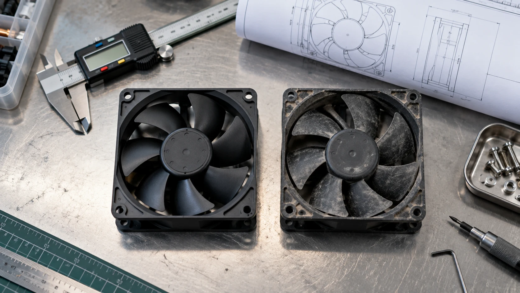
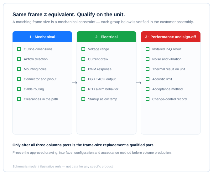
Frame size is a mechanical constraint, not equivalence.
Can a same-size fan replace a Sanyo Denki, SUNON, Delta, NMB or ebm-papst part?
Only after qualification. Check dimensions and airflow direction, then verify installed pressure and flow, voltage range, current, PWM/FG/RD behavior, connector, startup, noise, vibration, thermal result and the customer's change-control requirement.
What should be frozen before volume production?
Freeze the approved mechanical drawing, electrical interface, motor and bearing configuration, target operating point, acoustic limit, environmental conditions, acceptance method and change-control record. A good sample without a controlled production baseline is not a completed qualification.
What should I send to request a custom fan sample?
Send target airflow and static pressure at that airflow, temperature and altitude basis, voltage tolerance, PWM or other control interface, connector and pinout, available envelope, noise target, expected quantity and environmental constraints. A current part label helps, but it does not replace the operating conditions.
Can you customise cable length and connector selection?
Usually, cable length and connector choice are part of the fan interface review. Send the harness space, connector family or mating part, pinout, locking requirement, bend radius and exit direction. Confirm whether the cable runs beside a motor, power stage or sensor cable, because routing can affect noise and service access. Test the final sample with the intended harness, strain relief and mounting. The production configuration remains subject to the approved drawing and project agreement.
Should I control a fan by PWM or by changing its supply voltage?
PWM and voltage control are not interchangeable without checking the fan interface. PWM may provide a defined command while voltage control can affect startup, minimum speed, feedback and current. Confirm electrical limits, PWM frequency, duty convention, tach behaviour and low-speed stability for the selected model. Test the controller, harness and fan together at cold start, minimum command and the real pressure duty. Choose the interface that the complete equipment can monitor and qualify.
How should I choose a water or dust protection level for a fan?
Start with the enclosure exposure: dust, spray direction, washdown, humidity, condensation, drainage and service practice. An IP code describes a defined product test; it does not automatically describe the assembled cooling path. Filters, vents, cable exits, seals and pressure equalisation can change the result. Ask which protection claim applies to the exact fan configuration and what evidence is available, then validate the fan in the equipment boundary. Do not select an unverified IP level simply because an application sounds outdoor or industrial.
What bearing-life expectation should I use for a cooling fan?
Use the supplier's stated life definition and conditions, such as L10, rated speed, bearing type, orientation, temperature and duty cycle. L10 is a statistical comparison point, not a promise for every unit. Bearing temperature may differ from room temperature when the fan sits in a hot return path or beside a power device. Ask how temperature, orientation, starts and stops, contamination and storage affect the stated value. Validate a representative sample in the intended assembly and define the replacement or inspection rule.
What operating temperature range should be specified?
State the ambient range, air temperature at the fan, humidity, condensation risk, altitude and duration of each operating state. A room-temperature requirement is not enough if the fan is downstream of a heatsink or inside a sealed cabinet. Identify cold start, warm restart and transitions that can affect lubrication, electronics, noise or control response. Ask the supplier to distinguish catalogue capability from the result that must be validated in your assembly. Tie the final range to the approved fan configuration, control method and thermal acceptance procedure.
When should a fan be judged failed rather than simply running slowly?
Define failure using the equipment requirement, not RPM alone. A fan may rotate normally while a blocked filter, bypass route or damaged impeller leaves the heat source above its limit. Record supply voltage, command, speed feedback, airflow or pressure, noise, vibration and component temperature. Failure may include no start, locked rotor, unstable speed, abnormal noise, loss of feedback, insufficient installed airflow or a thermal limit exceeded. Set alarm delay and service action in the system specification, then confirm the thresholds with a representative sample and real installation.
Deep-dive answers
Go deeper: 45 short engineering answers.
Fan Selection & Operating Point
Replacement & Cross-Reference
Airflow & Pressure Measurement
Control & Signals
Noise & Vibration
Life & Reliability
Environment & Protection
Custom & Buying Process
Need a design review?
Turn the question into a testable sample plan.
MEGA Tech develops custom DC cooling fans around the customer operating condition and validates samples in representative equipment. We do not treat a matching frame size as proof of equivalent performance.
Use the fan selection tool →Discuss your requirement →