Megawatt charging changes the fan's job, not the need for fans
The Megawatt Charging System was written for a scale where forced air stops carrying the power path — and the natural first reading is that fans left the building. They did not. They moved.
SAE J3271 defines the Megawatt Charging System (MCS) for heavy-duty vehicles: charging equipment spanning roughly 440 kW at 350 A uncooled up to 3.75 MW at 3000 A with active cooling, per the Megawatt Charging System FAQ published by Argonne National Laboratory. The standard's own reliability expectation — better than a 99.99 % success rate for first-attempt session start — is an availability promise, and availability is a thermal property: hardware that derates or trips on a hot afternoon does not start sessions.
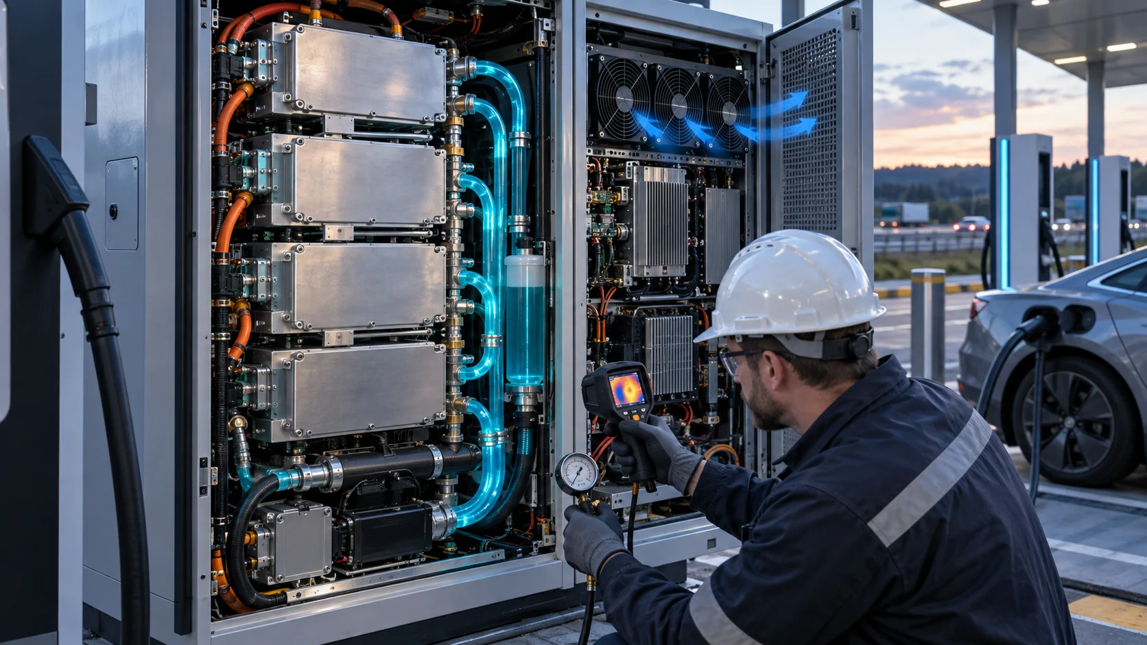
What actually changes above the few-hundred-kilowatt line is the division of labour. The power path — modules, busbars, cable, connector — hands its heat to a liquid loop, because air alone cannot cross the thermal resistance at the required density. But a liquid loop is a carrier, not a destination: the heat it collects has to be rejected to the sky, and rejection to sky is a fan's job. Around that main loop sit transformer stages, filter inductors, control compartments and cabinet climate zones that never touch coolant at all.
So the honest cooling specification for an MCS site has three fan questions in it: how big is the heat-exchanger fan bank, what still needs air inside the cabinets, and how the bank behaves when one of its number fails on the hottest afternoon of the year. This guide walks all three, on the same operating-point method used across this series — the operating-point validation guide is the arithmetic backbone.
The loss budget above one megawatt
Before selecting anything, count the heat and say where each watt lands. The budget at megawatt scale is dominated by a handful of predictable losses.
Industry analyses of high-power charging hardware converge on the same decomposition: switching and conduction losses in the power modules run at roughly 2–3 % of throughput, the AC input and transformer stages add another percent or so, and the cable-and-connector path dissipates its own share — on the order of 30–40 W per metre per conductor in a high-current cable, and a kilowatt or two at the contacts of a heavily loaded connector. A one-megawatt dispenser cabinet therefore carries on the order of 30–40 kW of continuous loss at full output, before the site's transformers are counted.
Two structural facts follow. First, the loss is continuous, not transient: a truck-stop dispenser may run near rated power for most of an hour, session after session, so the cooling plant is sized for a steady state, not a sprint. Second, the losses live in three different thermal domains — the liquid-cooled power path, the air-cooled auxiliary stages, and the cable loop — and each domain reaches ambient by a different route.
The table below is the budget sheet to agree on before any fan or radiator conversation. Every later selection in this guide hangs off one of its rows.
| Loss source | Typical magnitude | Thermal route to ambient |
|---|---|---|
| Power modules (IGBT/SiC) | 2–3 % of throughput | Cold plates → liquid loop → radiator → fan bank |
| Transformer / input stage | ~1–2 % of throughput | Forced air or own loop — an auxiliary air zone |
| Filter inductors, busbars | Fraction of a percent, concentrated | Local air path inside the cabinet |
| DC cable (high current) | ~30–40 W/m per conductor | Coolant jacket → shares the main loop's radiator |
| Connector contacts | ~1–2 kW at full current | Cooled connector → same loop; contacts held ≤100 °C |
| Control / aux compartment | Hundreds of watts | Sealed-zone plate or small air path |
Where air stops: the ceiling that forces the loop
Air cooling is not banned above a few hundred kilowatts by any standard — it is defeated by geometry, acoustics and the summer sun.
Heat rejection by forced air scales with the surface area you can expose and the airflow you can push across it, while charger output scales with the silicon and copper you can pack in. Vendor engineering analyses of the current generation put the practical continuous ceiling for an air-cooled cabinet in the region of 180–240 kW; beyond that, either the fin volume and airflow grow past what an outdoor cabinet can hold, or the acoustic footprint grows past what a truck-stop neighbours will tolerate. That ceiling — not fashion — is why the power path above it goes liquid.
The second defeat is seasonal. Typical air-cooled units begin shedding output near 40 °C ambient and can give away 30–40 % of nameplate by 50 °C — precisely the afternoons when cooling revenue peaks. A megawatt site designed around an air ceiling would spend its worst days derating its most expensive asset.
But the ceiling applies to carrying heat through the electronics, not to rejecting it outdoors. A radiator fed by a liquid loop is just a heat exchanger with an air side — and the air side still obeys every fan-selection rule in this series: a system curve, an operating point, a hot-day derating stack-up and an N+1 case.

Where the fan lives in a liquid-cooled MCS site
Walk a megawatt site's thermal map and the fans sit in three distinct habitats. Specifying them as one generic 'cabinet fan' is where selections go wrong.
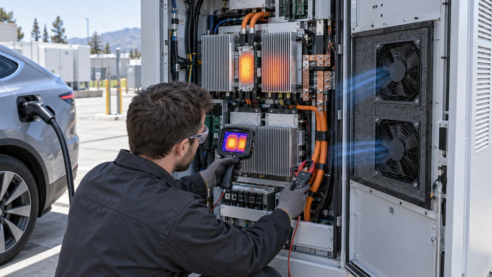
Habitat one is the heat-exchanger fan bank — the main event. Every watt the loop collects from modules, cable jacket and cooled connector leaves through a radiator or dry cooler, and the air side of that exchanger needs a fan array whose airflow crosses the exchanger's own system curve at design loop temperature and design ambient. This is a condenser-style duty: high airflow, moderate static, relentless hours, hot inlet air of its own making.
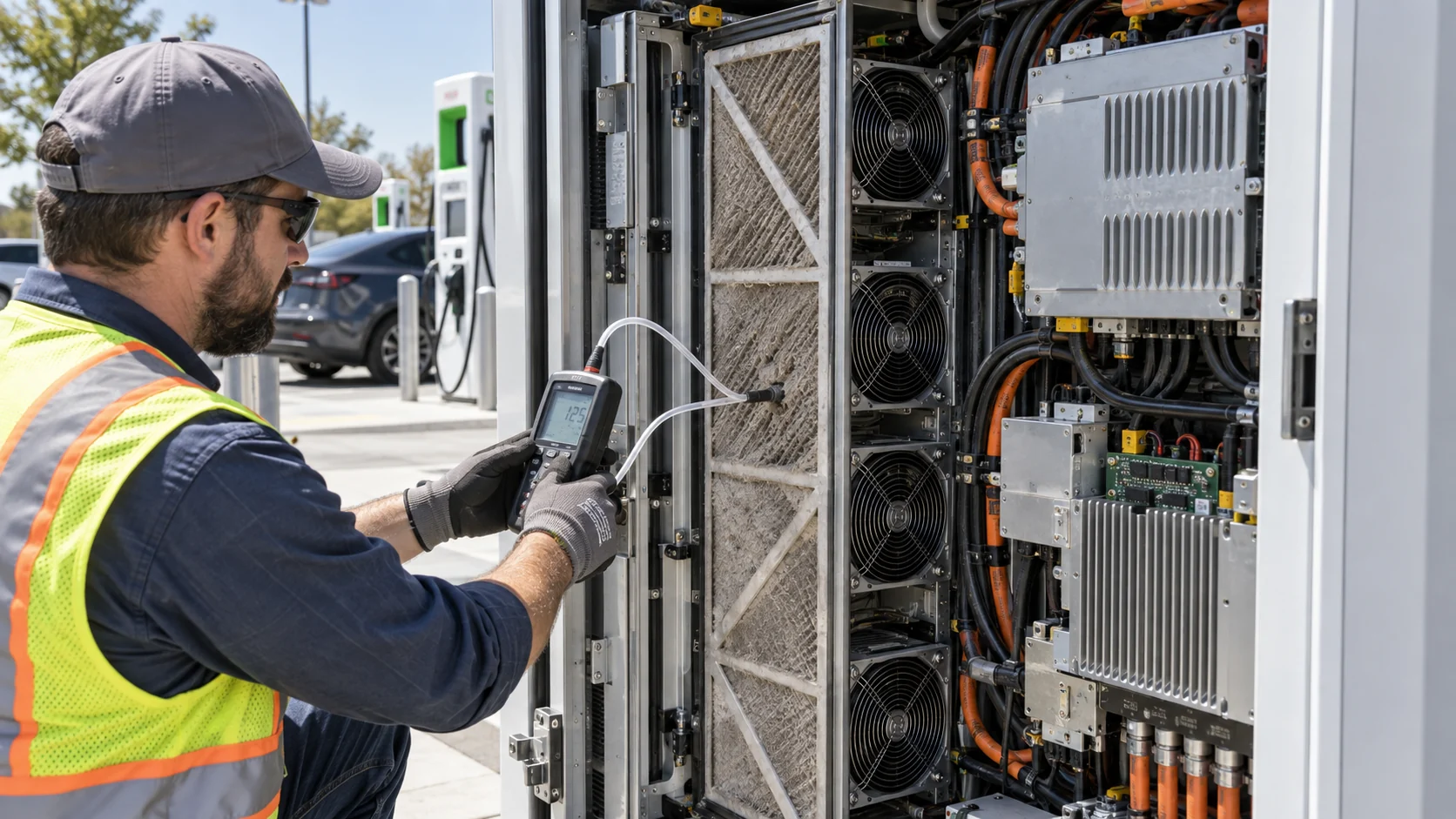
Habitat two is auxiliary air: the transformer and input stages, filter inductors, busbar runs and the control compartment that never touch coolant. These zones take directed airflow from dedicated fans or from a segregated cabinet air path, and they bring the usual site-dust questions — the filter pressure and derating diagnostics logic applies unchanged.
Habitat three is enclosure climate: sealed bays held clean by pressurisation, or ventilated bays exchanging cabinet air with the site's ambient. SAE J3271's own cooling ladder for the coupler — roughly 500 A uncooled, ~1500 A with a cooled connector, 3000 A fully cooled — is a useful reminder that the standard expects graded thermal architectures, not one recipe. The fan selection is graded with it.
Selecting the heat-exchanger fan bank
The radiator's air side is a familiar selection wearing new numbers: a system curve made of exchanger, grilles and duct, crossed at a hot-day ambient by a fan bank that must survive its own exhaust.
The system curve is dominated by the exchanger core — a dense, high-static component — plus intake louvres, discharge grilles and any ducting to the dry cooler. Close-coupled installations add the system-effect and clearance penalties: a fan pulling air through a tight elbow or discharging into a plenum never delivers its bench curve. Measure or model the installed curve, not the component curve.
The ambient is the second number to pin. Desert and mining sites design to 45–55 °C; the fan's bearing life runs on the inlet temperature it actually sees, which for a radiator discharge-aided bank is the hot-inlet arithmetic — preheated air, thinned density, and a P-Q curve that must still cross the system curve at the worst hour. Altitude stacks onto the same derating.
The third number is the loop's side of the bargain. The fan bank sets the air-side approach: more airflow buys a smaller exchanger and a cooler loop, at the price of acoustic level and fan power. The air–liquid hybrid validation in this series shows the trade being measured rather than assumed.

A worked duty point (illustrative numbers)
One worked radiator makes the method concrete. The numbers are illustrative — the method is the deliverable.
Take a 1 MW dispenser cabinet at 96.5 % efficiency: about 35 kW of loss, of which the loop collects roughly 30 kW from the cold plates and cooled cable. Design the site to a 45 °C ambient. Give the radiator an air-side temperature rise of 12 K and an approach of 10 K: the coolant runs near 55–65 °C, comfortably below the module limits that typically trigger derating in the mid-80s °C at the junction.
The air side follows from one line of arithmetic: rejecting 30 kW with a 12 K rise needs about 2.5 kg/s of air — roughly 8,000–8,500 m³/h at hot-day density. Against an installed static in the 100–150 Pa range (core, louvres, duct), that is a four-fan bank in the N+1 arrangement, each fan delivering its share with margin at nominal voltage.
Now the case that decides the selection: one fan fails at 45 °C. Three fans carry the whole airflow, each pushed further along its curve; the exchanger's approach widens, the loop creeps up, and the module margins spend from their reserve. If the three-fan point still crosses the system curve with the loop inside limits, the bank is honest. If not, the choice is a fifth fan or a bigger exchanger — decided on the parallel-fan N+1 arithmetic, not on optimism. The same failure-tolerant logic underpins the reverse-flow validation used on the site's dispenser-scale siblings.
Redundancy and the 99.99 % promise
MCS's availability expectation turns the fan bank from a component into an availability system, with detection, reporting and a tested single-failure case.
An availability promise is a chain, and the fan bank is one of its cheapest links to strengthen. The design case is explicit: the site holds full output with one radiator fan inoperative, at worst-case ambient, with the failure detected and reported — not merely tolerated until someone notices the noise change. Tach monitoring on every fan, PWM command versus speed feedback cross-checked, and a reported fault state make the N+1 case an operational fact instead of a paper claim.
The control law earns its keep here. A bank that idles at low duty through cool nights and ramps to its ceiling on hot afternoons needs a law with a duty floor that protects the loop's minimum approach even at light load — the same philosophy as the PSU control-law guide: keep the temperature-sensitive elements inside their life curve at every duty, not only at full load.
Availability arithmetic closes the section: a bank of four with one hot spare loses far less expected capacity to fan failure than a single large fan ever could, and the failed unit is a two-bolt swap during a charging lull. That serviceability — module fans you can replace without draining the loop — is part of the selection, not an afterthought.
Validation: prove the loop and the bank at the states that decide
A megawatt site validates at full output, worst-case ambient, real ducting — with instruments on the loop, the air and the fans themselves.
The deciding states are familiar from this series: full load at the top of the ambient range, in the installed enclosure with real ducting, louvres and site recirculation — not a bench radiator in open air. Instrument the loop's supply and return, the exchanger's air in and out, and the module cold-plate surfaces; record every fan's duty and tach at each state. The worst-case margin validation protocol carries over unchanged.
The fan bank's own behaviours are on the list: the single-failure case held for a sustained run, restart behaviour after a site power dip, acoustic level at the truck-stop property line with the bank at full duty, and the endurance re-check — agreed hours at the real thermal state, then the measurements repeated. A site that passes with the fans at their duty ceiling has no margin left; the selection revisits the fan, not the test.
Field reality closes the loop: summer derating complaints at megawatt sites are almost never a loop problem alone. They are an air-side problem — loaded filters, recirculated exhaust, a fan bank sized to mild-weather curves. The postmortem method shows the diagnostic sequence when the field comes back hotter than the test bench did.
- Full output, worst-case ambient, installed ducting: the loop verified, not assumed.
- Single-failure case: one radiator fan out, full output held, detection and reporting confirmed.
- Instrumented both sides: loop supply/return and exchanger air in/out, with every fan's duty and tach.
- Acoustic level at the property line at full duty — truck stops sit next to communities.
- Endurance re-check at the real state, then measurements repeated.
What MEGA Tech does with megawatt-charging cooling projects
We manufacture the fan side of the megawatt site — the heat-exchanger bank and the auxiliary air — and we work from the loop's promise backwards to the sky.
What we do: send us the loss budget, the loop's design temperatures, the exchanger geometry and the site's ambient envelope — or the radiator and cabinet to measure — and we propose a fan bank that crosses the installed system curve at worst-case ambient, an N+1 arrangement with detection and reporting that actually works, and auxiliary fans for the zones the loop never touches. Measured P-Q and acoustic data comes with every proposal, and the validation protocol is supported end to end, including the single-failure endurance run.
What we need from you: the output rating and efficiency figure behind the loss budget, the loop's design supply and return temperatures, the exchanger or dry-cooler selection, the site's ambient and altitude range, the acoustic limit at the property line, and the control interface the site's PLC expects.
Where our boundary is: we do not supply power modules, coolants, pumps, liquid-loop plumbing or site controllers. Our scope is the air side — the fans, their data, and the measured proof that the bank rejects the loop's heat at the hour that decides.
Recommended Fan Starting Points
These catalogue series may be suitable starting points for this application. Final selection depends on the installed airflow, static pressure, voltage, noise target and operating environment.
Request a sample for validation on your equipment.
Engineer FAQ
The questions engineers actually ask about megawatt-site cooling, with the short engineering answers.
Q: If the power path is liquid-cooled, why does the site need a fan bank at all? A: Because a loop is a carrier, not a destination. The heat collected from modules, cable and connector leaves through a radiator, and radiator-to-air is airflow. Bigger loops do not change that; they enlarge the radiator and its fan bank.
Q: At what power does air cooling actually stop? A: There is no single number, but current-generation analyses cluster the practical continuous ceiling for an air-cooled cabinet around 180–240 kW. Above it, fin volume, airflow and acoustics grow faster than the rating does.
Q: What size is the heat rejection at 1 MW? A: Order-of-magnitude, 30–40 kW of continuous loss at full output for the dispenser cabinet, depending on efficiency and where the transformer sits. The radiator and fan bank are sized to that steady state, because truck-stop duty is steady.
Q: Does the coupler always need active cooling? A: SAE J3271's own ladder runs from roughly 500 A uncooled through a cooled connector near 1500 A to 3000 A fully cooled — graded with power, not binary. The site's loop and its air side grade with the same logic.
Q: How is the fan bank made redundant? A: N+1 or better, with each fan tach-monitored and the single-failure case tested at full output and worst-case ambient — full airflow from the survivors, loop inside limits, fault detected and reported. A paper N+1 that has never run with a fan out is a hope, not a redundancy.
Q: What derates first on a hot afternoon — the loop or the fans? A: They fail together if the selection was mild-weather-only: thinned, hotter air moves the fan's operating point and widens the exchanger approach at the same moment. Design the crossing point at the worst hour, then the afternoon is ordinary.
Questions for a design review
Take these to the review with the loss budget, the loop schematic and the site's ambient statistics on the table.
Megawatt-site reviews that only audit the loop produce sites that derate in July. These questions close both halves — liquid and air.
- Has the loss budget been agreed per domain — modules, input stage, aux zones, cable, connector — at full output?
- Does the exchanger fan bank cross the installed system curve (core, louvres, duct, system effect) at worst-case ambient, not the bench curve?
- Does the single-failure case hold full output with one fan out, at the worst hour, with detection and reporting proven in test?
- Do the auxiliary air zones — input stage, inductors, control bay — have their own selection, filters and sensors, or are they living off the loop's leftovers?
- Has the fan bank's bearing life been checked against the inlet temperature it actually sees in recirculated, preheated air?
- Is the acoustic limit at the property line part of the selection, with the fan speed law built around it?
- Does the endurance re-check run at the real thermal state and repeat the loop, air-side and fan measurements afterwards?