Why N+1 fan count is not an N+1 thermal result
N+1 is a useful availability rule for an EV fast-charger cabinet, but it is not automatically an N+1 cooling result. When one fan stops, the surviving fans see a different system curve, a different pressure balance and sometimes a reverse-flow path through the failed branch.
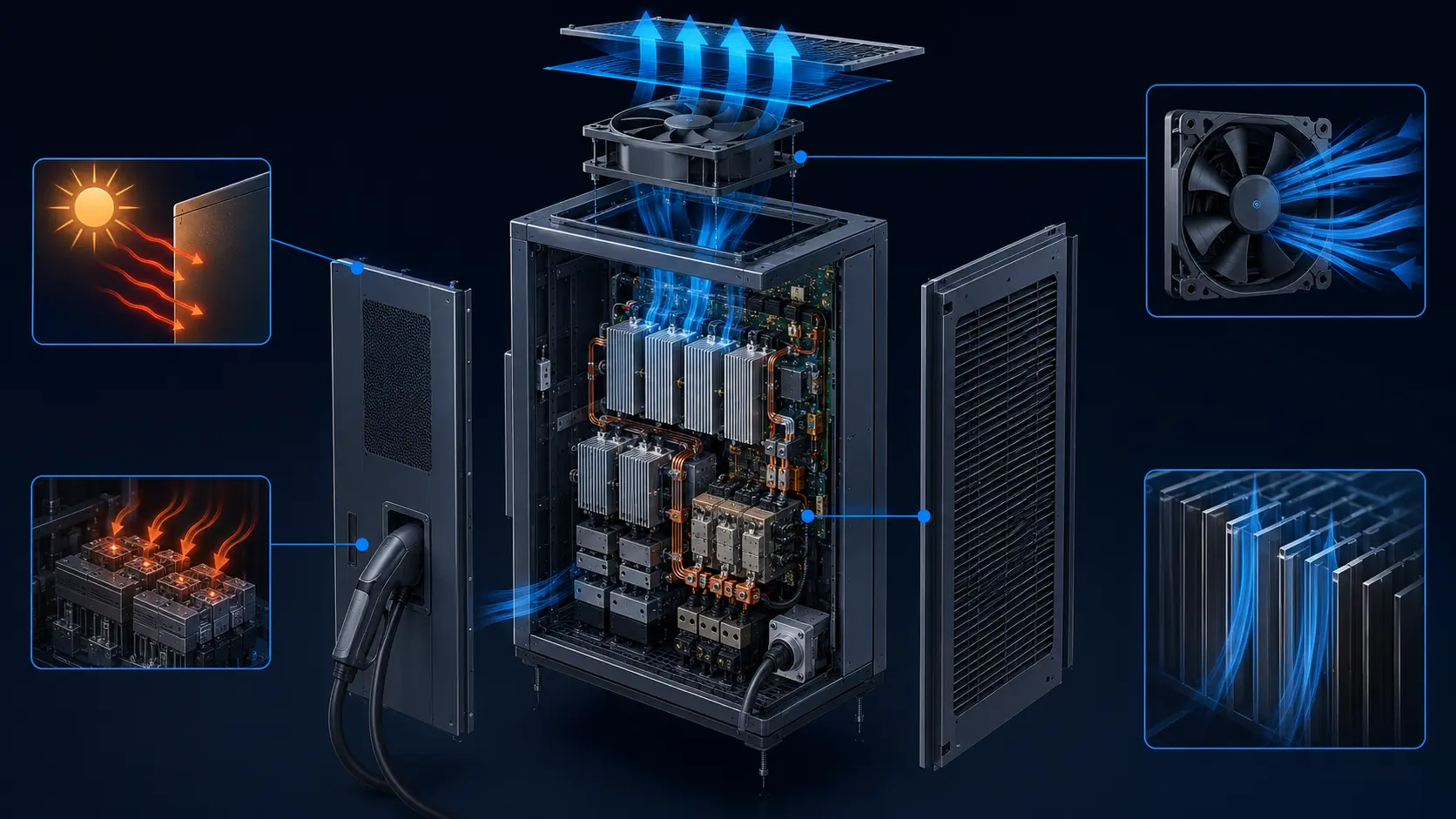
A charger may continue to deliver power after one cooling fan is unavailable, yet the heat sink may no longer receive the airflow assumed by the normal operating design. The remaining fans may run faster, the controller may report healthy tachometer pulses and the cabinet may sound normal, while a filter, louver, shroud or open fan port redirects part of the air away from the power devices.
The engineering question is therefore not simply how many fans remain. It is whether the remaining fan set can deliver the required heat-sink airflow at the failed-state pressure, ambient temperature and cabinet configuration. N+1 should be validated as a complete air-path state, not accepted from the fan count alone.
Start with heat load and the air-side duty
Fan selection should begin with the heat that the cabinet must reject, then convert that heat into a required mass flow and an installed pressure target. A catalogue maximum CFM is only one point in a test configuration; it does not define the charger operating point.
For a first estimate, sensible air cooling can be written as Q = m-dot times cp times delta-T. Using air density near 1.2 kg/m3 and cp near 1.005 kJ/(kg K), a 3.0 kW air-side heat load with a 15 K air temperature rise needs about 0.199 kg/s, or about 597 m3/h, before cabinet losses and design margin. This is an engineering estimate, not a guarantee: power-device distribution, bypass leakage, altitude, inlet temperature and sensor location still need validation.
The same calculation can expose an optimistic fan specification. If four fans share that illustrative 597 m3/h duty, the average useful flow is about 149 m3/h per fan in the normal state. If the design assumes 430 m3/h per fan, the extra capacity may be useful pressure margin rather than useful delivered air. The value must be checked against the system resistance curve, not counted as free-air capacity.
For outdoor chargers, include the air temperature at the cabinet inlet rather than the weather-station value alone. The cabinet may ingest recirculated exhaust air, solar-heated air or air warmed by an adjacent charger. If the design is expected to operate at 50 C inlet air and the thermal model used 25 C, the available semiconductor temperature margin is already smaller before a fan fault occurs.
| Input | Why it matters | Evidence to collect |
|---|---|---|
| Heat load | Sets the air mass flow and heat-sink temperature rise | Worst-case real or simulated electrical load |
| Air temperature | Changes thermal margin and air density | Inlet temperature at the cabinet during the duty cycle |
| System resistance | Moves the operating point on the fan curve | Pressure taps or validated CFD plus final hardware |
| Fault state | Changes flow sharing and may create reverse flow | Open-port and isolated-branch measurements |
| Acceptance limit | Defines whether N+1 is actually useful | Named sensor locations, load duration and maximum temperature |
The installed system curve changes after one fan stops
The animation below compares the three states that are often collapsed into one word: redundancy. Blue particles represent intended forward flow; red particles represent the reverse path through an open failed branch. The drawing is qualitative, but the pressure logic is real.
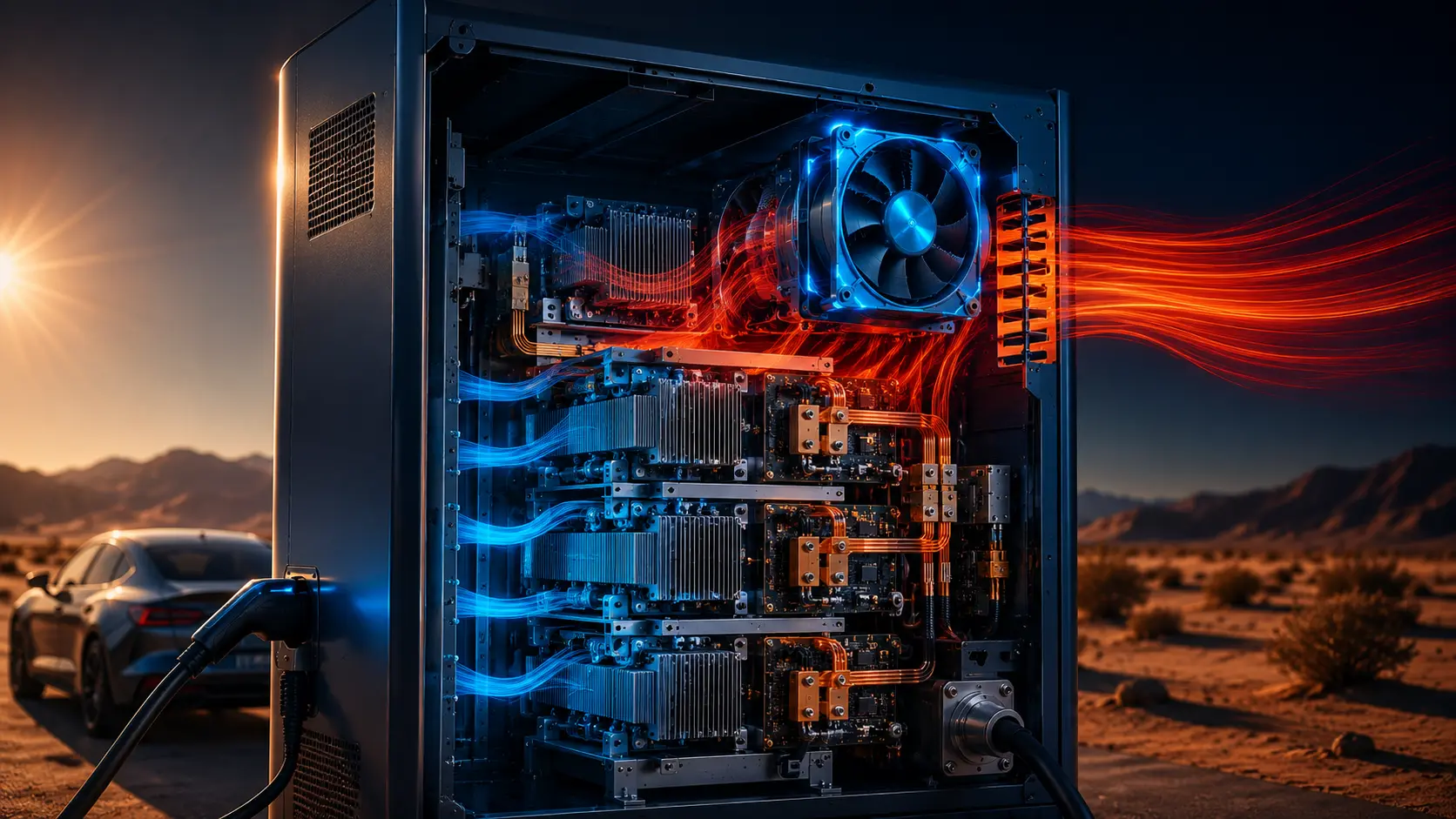
In the normal state, each branch contributes flow and the cabinet resistance is shared. When one fan stops and its opening remains available, the surviving fans can pressurize the common air chamber while part of the air moves backward through the stopped rotor. That branch is not neutral: it becomes a parallel leakage path with its own resistance and may reduce the useful flow through the heat sink.
When a damper, shutter or suitable check arrangement isolates the failed branch, the reverse path is reduced. The remaining fans still operate on a new curve because total flow, air-chamber velocity and branch resistance changed, but the result is usually easier to predict and validate. The isolation device must itself be included in the pressure-drop budget and checked for service reliability.

Reverse flow is a pressure-loss problem, not only a fan fault
A stopped fan can behave like an obstruction, a leakage path or both, depending on rotor geometry, shroud design and the pressure difference across the branch. Treating it as simply zero airflow misses the load that the remaining fans must overcome.
The failed branch may also pull dust, moisture or warm discharge air toward a sensitive region when the cabinet pressure pattern reverses. A check device can improve the air-path definition, but it adds pressure loss, acoustic behavior and a failure mode of its own. A damper that sticks closed during normal operation can be as damaging as a fan that stops, so the design needs an air-chamber position check or a commissioning test.
Use the fan P-Q curve and the cabinet resistance curve together for every state. The normal curve, failed-open curve and failed-isolated curve should not be assumed to be parallel translations. A change in flow distribution can alter the effective resistance of filters, heat sinks and air chambers, especially when the cabinet contains sharp turns or uneven branch lengths.
A practical review should ask where pressure is measured. A single pressure tap near the fan can look healthy while the heat sink receives less flow because of bypass. Measure the pressure difference across the relevant restriction and pair it with heat-sink inlet/outlet temperatures or direct flow evidence. NREL's electric-drive thermal analysis is a useful reminder that the thermal result depends on the interaction of heat sinks, fans and the complete cooling path, not one isolated component.
Worked example: four fans, one failed branch
The following numbers are an illustrative calculation to show the method. They are not MEGA Tech catalogue data and must not be used as a charger acceptance limit.
Assume a cabinet uses four identical fans. At the normal installed working point, each fan contributes 430 m3/h at approximately 180 Pa, so the useful total is about 1,720 m3/h. If one fan stops and remains open, the three surviving fans may each fall to 365 m3/h because they now see a different common pressure. Suppose the stopped branch allows 90 m3/h of reverse or bypass flow. The useful forward flow becomes approximately 3 times 365 minus 90, or 1,005 m3/h.
That is a 715 m3/h reduction, about 41.6% below the illustrative normal state. The surviving fans are still turning and may still report credible FG pulses. The thermal risk comes from the installed flow loss, not from a missing tachometer signal alone. If the failed branch is isolated and the reverse flow is reduced to 10 m3/h, the illustrative useful flow becomes about 1,085 m3/h. That is better, but it is still far below the normal 1,720 m3/h and must be checked against the heat load.
The example also shows why simply increasing RPM after a fault may not solve the problem. A higher command can move the survivors along their curves, but the motor, noise, power and bearing life all change. The correct response may be a larger high-static-pressure fan, a better air chamber, a controlled isolation path, reduced charger power in the fault state, or a combination of those decisions.
| State | Forward fan flow | Reverse/bypass | Useful flow | Interpretation |
|---|---|---|---|---|
| All four running | 4 × 430 = 1,720 m3/h | 0 | 1,720 m3/h | Normal reference state |
| One stopped, branch open | 3 × 365 = 1,095 m3/h | 90 m3/h | 1,005 m3/h | 41.6% lower than normal |
| One stopped, branch isolated | 3 × 365 = 1,095 m3/h | 10 m3/h | 1,085 m3/h | Better, but still needs thermal proof |
Fault detection needs more than FG feedback
FG or tachometer feedback is valuable for detecting a rotor that is stopped, slow or unstable. It does not tell the controller whether the working air path is delivering enough cooling to the power module.
A robust charger can combine fan current, command, FG, branch pressure, inlet temperature, heat-sink temperature and, where practical, damper position. These signals serve different questions. Command says what was requested; FG says what the rotor reported; pressure says what restriction the air path created; temperature says whether the electronics are actually within margin.
Control logic should define the degraded operating mode before a fault happens. Examples include limiting charger power, increasing the remaining fan command within a validated envelope, opening a service alarm, or requiring an immediate shutdown. The correct action depends on semiconductor temperature limits, thermal time constant, ambient conditions and the validated fault-state curve.
| Signal | Useful question | Limitation |
|---|---|---|
| PWM command | What duty did the controller request? | Does not prove delivered flow |
| FG / tach | Is the rotor speed plausible? | Does not show branch or heat-sink airflow |
| Fan current | Is the motor load changing? | Needs a reference for voltage and operating point |
| Differential pressure | Did a named restriction change? | Only describes the taps that were chosen |
| Heat-sink temperature | Is the thermal result acceptable? | Sensor location and time response matter |
| Damper position | Did the failed branch isolate? | Position feedback does not prove seal performance |
Noise, power and bearing life are part of the fault-state design
A redundancy strategy that survives thermally but drives every remaining fan at an acoustic or electrical limit is not a complete product strategy. The failed-state duty can be longer than the service team expects if a charger remains available until the next maintenance window.
Higher speed generally increases acoustic output and input power, while the fan's bearing, motor and electronics experience a different duty profile. Compare normal and degraded states at the actual pressure point rather than comparing free-air noise or a nominal RPM. If the charger is installed near homes, depots or workplaces, the degraded state may be the state that attracts the first complaint.
For long-life equipment, define whether N+1 is a short ride-through mode or a permitted continuous operating mode. The answer changes the required L10 bearing life, thermal derating, alarm response and service interval. A design that uses N+1 only long enough to reduce power and reach a safe service state can make different trade-offs from a design expected to run for months with one branch unavailable.
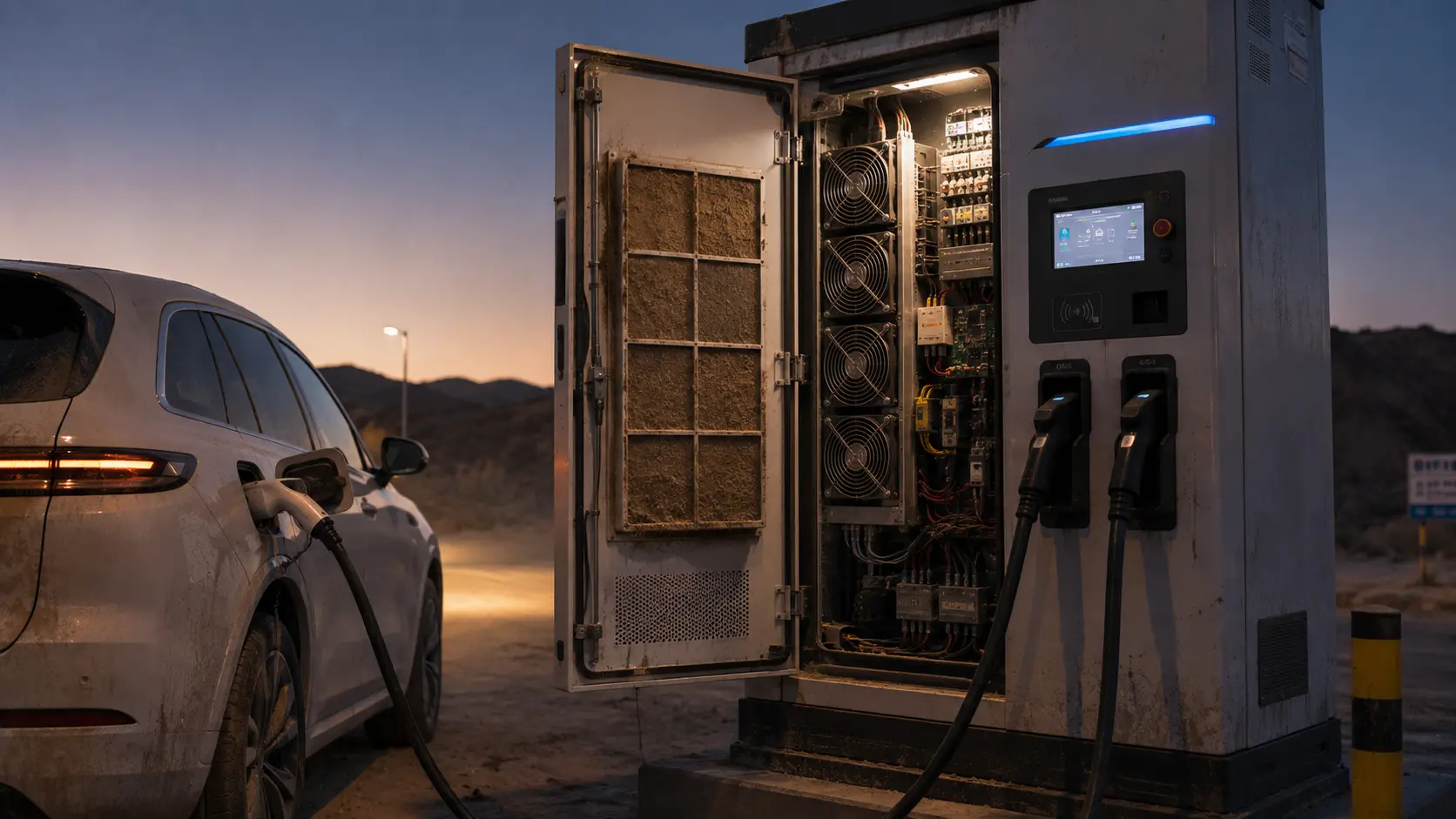
Dust and filter loading should be included in both states. The failed-open branch may lower useful flow while a loaded filter raises the common pressure, so the combination can be worse than either fault alone. A commissioning plan should include the credible maintenance state, not only a new filter on a clean bench.
Procurement should also ask how the fan is expected to behave during a restart. A stopped branch may be electrically disabled, mechanically blocked or intermittently retried by the controller. Each condition can create a different current transient, acoustic event and pressure disturbance. Record the restart policy, minimum supply voltage and alarm delay so a supplier is not asked to validate an undefined fault sequence.
For a production decision, compare at least three repeated runs rather than accepting one favorable trace. Check whether the degraded temperature rise is repeatable, whether the damper returns to the same position, and whether the pressure signal settles after the controller changes speed. Repeatability is especially important when the temperature margin is only a few degrees, because sensor placement and ambient drift can otherwise look like a fan improvement.
Where MEGA Tech fits in an EV charger fan review
MEGA Tech is a custom cooling-fan manufacturer focused on application matching rather than a free-air catalogue number. For a DC axial-fan sample review, the useful starting point is the installed requirement: envelope, voltage, airflow, pressure, noise, control signals and the fault-state acceptance plan.
We can review an original fan part number, a cabinet sketch or photographs, the pressure target, PWM/FG/RD requirements and the intended duty. Based on that information, we can help define a practical sample for fit, signal and installed thermal evaluation. Replacement work should still be accepted by the customer's own cabinet test, because a part-number match without system evidence is not a reliable engineering conclusion.
The current scope described here is custom DC axial cooling-fan development and sampling. It is not a claim that every EC, liquid-cooling or facility-air system can be replaced by a single catalogue fan. If the application needs a high-static-pressure axial variant, a particular connector, feedback behavior, small batch or a price-sensitive alternative to a branded fan, those requirements should be written into the sample request and verified at the real working point.
For a technical review, send the heat load, ambient range, fan count, failed-state definition, inlet and outlet arrangement, filter/louver details, available space, voltage, control interface, acoustic limit and temperature acceptance points. That lets the supplier discuss the complete cooling path instead of guessing from a maximum CFM headline.
For purchasing, the sample request should name the evidence required at delivery: fan curve points or a test report, current and speed limits, connector pinout, alarm behavior, operating-temperature range and the proposed fault-state test. This keeps a lower-cost replacement from being judged only by dimensions or free-air airflow. It also gives the customer a fair comparison between the original fan and the custom sample at the same voltage, filter condition, cabinet pressure and load duration.
Engineer FAQ: EV fast-charger fan redundancy
These answers are deliberately tied to the installed cabinet rather than a generic fan rating.
Q: Does N+1 mean the charger keeps the same thermal performance after one fan fails? A: No. It means the architecture has a defined redundancy intent. The surviving fans, common air chamber and failed branch must be tested to establish the actual thermal margin.
Q: Should the failed fan be left open or isolated? A: Do not decide from convenience. Compare both states. An open branch can become a reverse-flow or bypass path; an isolation device can reduce that path but adds its own pressure drop and failure mode.
Q: Can I increase PWM until the temperature falls? A: Only inside a validated speed, current, noise and life envelope. A higher command does not guarantee more useful heat-sink flow if the cabinet is bypassing or severely restricted.
Q: What is the most important measurement during a fault test? A: No single measurement is enough. Record the load, inlet temperature, fan command, FG, pressure across named restrictions, heat-sink temperatures and the exact cabinet configuration on one time base.
Q: What should I give a fan supplier? A: Provide the fan envelope, voltage, target operating point, pressure, noise, PWM/FG/RD needs, filter/louver state, normal and failed fan states, ambient range, duty cycle and acceptance temperatures.
Questions for a design review
Use these questions before freezing a redundant fan wall or approving a replacement fan for production.
1. What heat load and inlet-air temperature define the worst credible charge condition? 2. What are the measured or modelled resistance curves for normal, failed-open and failed-isolated states? 3. Where can reverse flow bypass the heat sink? 4. Is the failed-state mode temporary or continuous, and what power derating follows it? 5. Are PWM, FG, current, pressure and temperature logged together? 6. Does the acceptance test use the final filter, louver, shroud and service-panel configuration? 7. What is the evidence that a damper or check arrangement will remain reliable across the service life? 8. Is the candidate fan evaluated at its installed operating point rather than its free-air maximum?
For a project review, compare the proposed fan curve with the three system states, then validate the result with the actual charger cabinet. A compact prototype or replacement sample is most useful when the acceptance conditions are written before the sample is ordered.
Validate the working point before the fan count
A redundant fan architecture is credible when it protects the thermal path, not merely when it keeps a motor spinning. Test the installed system curve, reverse-flow behavior, sensor evidence, acoustics and life duty in the states the charger will actually experience.
If you are evaluating a DC axial-fan sample for an EV charger, share the heat load, cabinet arrangement, pressure target, fan count, failed-branch strategy, voltage, signal requirements and acceptance temperatures. MEGA Tech can help structure a practical sample and validation plan around the installed working point.
Explore the EV and automotive cooling applications or continue with the EV charger PWM and RPM validation guide.