A healthy fan signal can still accompany a hot heat sink
In an EV fast charger, a controller can command a fan to 80%, receive a credible tachometer signal and still leave the power-electronics heat sink short of the air it needs. That is not a contradiction. It is a measurement-boundary problem.
PWM is a command. FG or tach is evidence that the rotor is turning at a reported speed. Neither value directly measures the pressure available across the installed air path, the mass flow through a particular fin stack, or the temperature margin at the semiconductor junction. A field team that treats those signals as proof of airflow can replace a perfectly healthy fan and leave the actual restriction, bypass path or recirculation loop untouched.
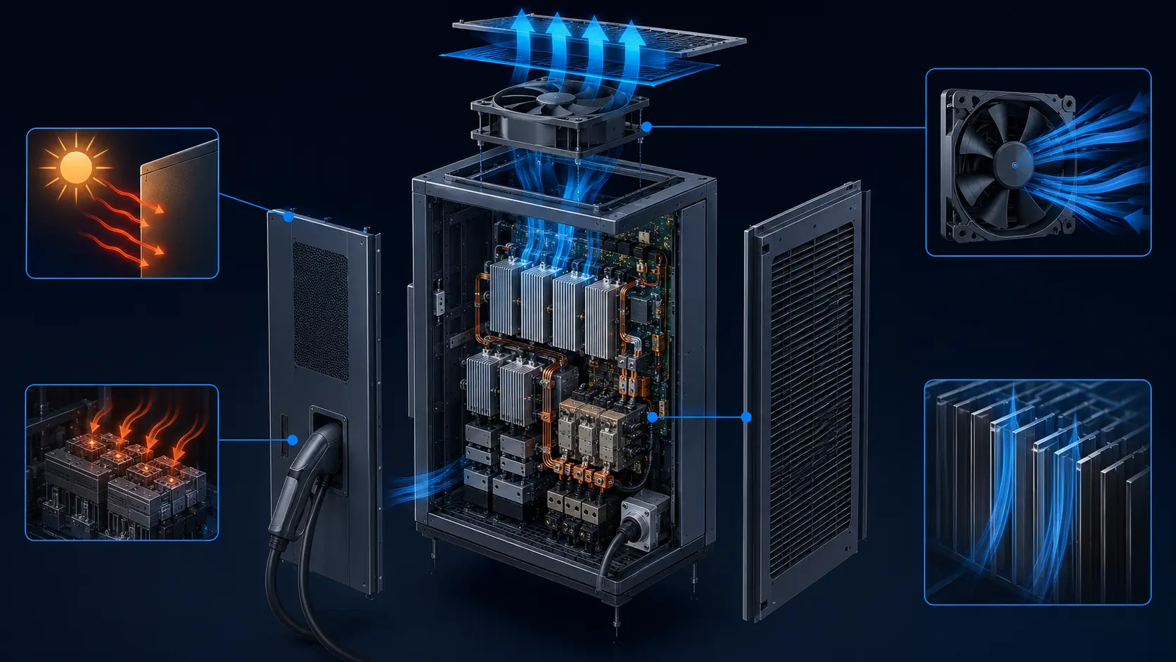
This matters most during parked, high-duty charging. The charger cabinet must create its own cooling path: ambient air enters through louvers or filters, crosses heat sinks and power modules, then exits without being pulled back toward the inlet. It has no vehicle-speed airflow credit. A cabinet can therefore sound active and show a normal RPM while its thermal path is quietly degrading.
What the fan test tells you - and what it does not
A fan curve is still essential. It shows the pressure-flow relationship for a defined test configuration. AMCA 210 describes standardized laboratory methods for determining aerodynamic performance, while SAE J2867 treats an electric cooling fan assembly as a system with airflow, pressure and electrical input to be measured. Those are useful foundations, but an installed charger cabinet adds filter loading, louver geometry, cable bundles, heat-sink fin density, service clearances and outlet recirculation.
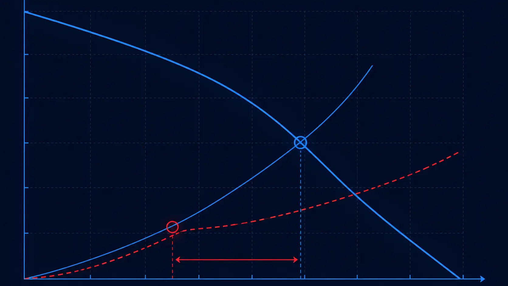
The installed working point is where the fan curve meets the cabinet resistance curve. If the resistance rises because a filter loads or an inlet is partly blocked, the operating point moves toward lower flow and higher pressure. The motor can continue to spin near the expected speed. With a speed-controlled fan, the controller may even increase PWM and make the acoustic symptom more noticeable while the gain in useful heat-sink flow is small.
This is why a commissioning sheet should never contain only “fan on / fan RPM / pass.” It should preserve the configuration that produced the result: which panels were installed, filter condition, door position, ambient temperature, supply voltage, commanded duty and the location of every temperature sensor. The earlier fan P-Q curve guide explains the operating-point logic in more detail.
Parked charging is its own airflow state
Vehicle thermal systems can receive ram-air assistance while the vehicle moves; a stationary fast charger cannot. Its inlet and outlet placement, cabinet clearances and local site conditions set the air-side boundary. A charger installed close to a wall, under a canopy with a low ceiling, or beside another heat-rejecting cabinet can ingest warmer discharge air than the ambient value reported by a weather service.
That distinction is useful during fault finding. A high heat-sink temperature at a quiet indoor bench is not automatically comparable with a warm outdoor cabinet during a long charge session. The test needs a named reference: ambient outside the cabinet, air at the fan inlet, heat-sink base, and cabinet exhaust. The temperature difference between those points is often more actionable than a single absolute temperature.
SAE vehicle thermal-system studies similarly model the radiator, fan, flow path and measured pressure losses together rather than treating the fan as an isolated component. The same discipline transfers to charger cabinets: validate the air path that the electronics actually see, not only the fan on an open bench.
There is also a timing issue. Metal heat sinks, thermal interfaces and cabinet air have different thermal time constants. Immediately after a power step, fan RPM can react quickly while the heat-sink-base sensor has not yet settled. Immediately after a power reduction, the reverse can happen: a high temperature remains even though the command has already fallen. A useful test plan therefore specifies a stabilization criterion or a fixed observation window instead of accepting the first value that appears on a service display.
Do not hide this uncertainty by averaging unrelated events. Keep the load profile, cabinet state and observation period in the test record. If a site alarm happens after a defined high-load period, reproduce that sequence as closely as practical. The objective is not to create a laboratory-perfect copy of the site; it is to make the before-and-after comparison technically honest.
The same PWM and RPM can hide three different installed states
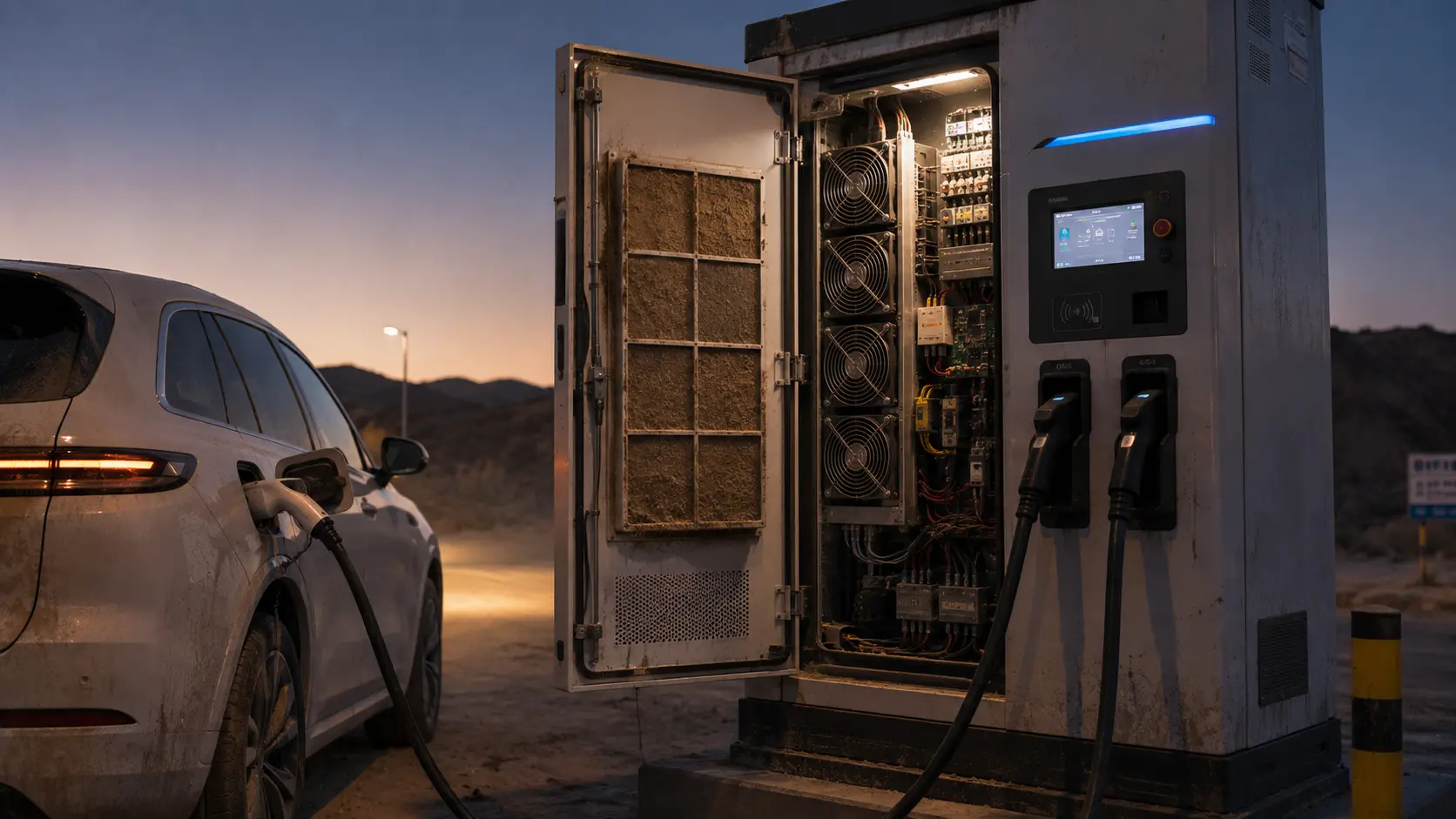
The schematic below uses the same command and reported rotor speed in all three panels on purpose. In the clean state, most of the air crosses the intended heat sink. In the loaded-filter state, the air path needs more pressure and useful flow falls. In the recirculation or bypass state, some discharge air returns toward the inlet or avoids the fin stack. The controller can see a normal-looking electrical signal in every panel; the heat sink experiences three different cooling conditions.
Do not turn this illustration into a universal threshold. The pressure drop, fan curve, fin geometry and control response are specific to the cabinet. Its value is to define what must be measured before declaring a fan or a control algorithm at fault.

Build one commissioning record on one clock
The fastest way to create ambiguity is to compare an RPM sampled at one moment with a temperature sampled after the load step has already changed. Put the fan command, electrical input and thermal readings on one time base. A data logger is ideal, but a disciplined manual record can still reveal a pattern if the load step and sample time are explicit.
For a repeatable trial, begin with a documented clean configuration, establish a stable electrical load, then change only one condition at a time. Examples include a controlled filter state, a louver cover position or a programmed fan command. This is more defensible than changing a fan, a filter and a control setting in the same test and then guessing which change helped.
Choose pressure taps that answer a physical question. A tap upstream and downstream of the complete inlet assembly can show inlet loss, while a different pair can characterize a heat-sink or outlet path. They are not interchangeable. Keep tubing short and protected from vibration, avoid placing a tap where a local jet dominates the reading, and document the orientation. If the instrument reports only a very small difference, do not over-interpret it: check its range, resolution, zero and repeatability before using it to justify a component decision.
Temperature sensors require the same discipline. “Cabinet temperature” is not a sufficient location. A sensor in free discharge air may show a different condition from one attached to the heat-sink base near the hottest power device. Record whether the sensor is taped, bonded, inserted into a pocket or read through the controller, because the attachment changes response time and sometimes absolute reading. Those details make a later review productive rather than argumentative.
| Evidence | What it answers | How to record it |
|---|---|---|
| PWM command and supply voltage | What did the controller request, and could the drive deliver it? | Log command %, supply voltage and fan current at each load state. |
| FG / tachometer | Did the rotor report the expected speed trend? | Record RPM with the fan identity and firmware/control mode. |
| Air-side differential pressure | Did installed restriction change across the filter, louver or heat-sink path? | Name the two pressure taps and keep the panel/filter configuration fixed. |
| Inlet, heat-sink and exhaust temperatures | Did the intended thermal path remove heat? | Record sensor locations, attachment method and the time since the load step. |
| Cabinet configuration | Could a mechanical detail explain a different result? | Photograph panels, door position, filter state and nearby obstructions. |
Read fault signatures before replacing a fan
These are hypotheses, not remote diagnoses. Their purpose is to stop a team from using a normal FG pulse as a reason to ignore the physical air path. A detailed filter loading and fan-life article covers why a rising restriction changes both duty and service risk.
| Observed pattern | What it can mean | Next check |
|---|---|---|
| PWM rises, RPM rises, heat-sink temperature still rises | Restriction, bypass, recirculation or a heat-transfer issue may dominate. | Check installed pressure points, filter/louver condition and inlet-to-exhaust temperature path. |
| PWM rises, RPM remains low or unstable | Electrical supply, fan drive, wiring, connector, command interpretation or mechanical drag needs investigation. | Verify supply at the fan under load, signal definition, connector retention and swap-test only after recording evidence. |
| RPM appears normal, exhaust air is only slightly warmer, heat sink is hot | Air may be bypassing the fin stack, or the thermal interface/load distribution may be the limiting path. | Inspect shrouds, gaps, fin blockage and heat-sink/contact condition. |
| Temperature rises mainly after service or panel replacement | A missing baffle, reversed filter, changed cable routing or panel clearance may have altered the system curve. | Compare photographs and measured pressure with the validated build state. |
| Alarm occurs only in hot or enclosed site conditions | Inlet-air temperature or discharge-air recirculation can consume margin without a fan electrical fault. | Measure cabinet inlet air at the event and inspect surrounding clearances. |
Treat filters, louvers and service panels as part of the fan selection
Fans are often selected from a free-air maximum airflow number, then asked to serve a cabinet whose final inlet hardware was not present in the first test. That creates a predictable gap between a catalogue comparison and the installed working point. The filter is not an accessory in this calculation; it is a pressure-loss component whose condition changes with maintenance interval and site exposure.
Likewise, a louver can protect against water ingress yet create approach losses, and a service panel can become an unintended short circuit if it leaves a gap near the heat sink. An air baffle that looks minor in a CAD assembly can decide whether flow crosses fins or returns to the nearest low-resistance route. The relevant design review question is not “what is the fan's maximum CFM?” but “which path does the air take at the required load, with the final enclosure assembled?”
When the required pressure is high, do not assume a larger axial part automatically fixes the issue. Compare candidate curves at the expected system resistance, check noise at that working point and preserve margin for the dirtiest credible operating condition. See the installation-clearance guide for the system effect created by tight inlets and outlets.
Define a fan module, not only a fan part number
For an EV charger program, the mechanical and electrical integration needs a specification that survives prototype changes and service replacement. A frame size and nominal voltage are only a starting point. The procurement and engineering teams should agree on the installed performance target, connector and pinout, PWM behavior, FG or alarm requirement, cable routing, mounting, environmental exposure, acoustic limit and validation method.
MEGA Tech develops custom DC axial cooling-fan samples around the application requirements that a customer provides: available space, voltage, airflow target, pressure target, noise limit, control/feedback signals and intended duty. That can include a sample for fit and thermal evaluation before volume production. The engineering scope is not a claim that any catalogue fan will match every EC, liquid-cooling or facility-air system. The final selection still needs the system curve, electrical interface and installed test result.
For replacement work, bring the original part number and the application evidence rather than only its headline airflow. A technically credible replacement conversation asks where the original fan operates, what the enclosure resistance is, which signal functions are required, and how the result will be accepted in the real cabinet.
A practical acceptance plan can be concise. Define the electrical load states to be tested, the maximum permitted sensor temperatures or temperature rises, the final enclosure configuration, the supply-voltage range, the control mode and the observation time after each step. Define any acoustic measurement condition separately; a sound reading at an arbitrary distance in a reflective workshop is not equivalent to an installed acoustic requirement. If dust, water, salt or high ambient temperature are relevant, name the exposure and the validation method rather than treating an IP label as a complete reliability program.
This is also where small-batch development can be valuable. A prototype fan sample can answer fit, connector, signal and installed thermal questions early, before a purchasing decision locks the cabinet around a free-air catalogue comparison. It does not replace the final validation, but it makes the final validation much less likely to reveal a basic integration mismatch.
A practical field sequence for a charger thermal alarm
This sequence is deliberately conservative. It produces a record that a thermal engineer, a service team and a supplier can review together. It also prevents the costly loop of shipping replacements before anyone has shown that the existing module was the limiting factor.
Where safe access is not possible during energized operation, stop and use the equipment maker's approved procedures. The diagnostic framework does not override electrical-safety, lockout/tagout, high-voltage isolation or site rules. In practice, the best record often combines non-invasive controller data with temperatures and pressure points designed into the enclosure for service access. Designing those access points early can reduce future troubleshooting time without asking a technician to disturb high-energy hardware.
Engineer questions about EV charger fan diagnostics
Questions that keep the field diagnosis tied to evidence from the installed cabinet.
Q: Can a normal RPM prove that the cabinet has enough airflow? A: No. RPM proves a rotational behavior, not the pressure-flow operating point through the assembled filter, louvers, fin stack and outlet. Pair it with installed pressure and temperature evidence.
Q: Should a fan be sized from maximum free-air CFM? A: No. Use its curve against the cabinet resistance curve at the intended load state, then retain an explicit margin for credible restriction and inlet-air conditions.
Q: Is differential pressure alone enough? A: No. It describes a named part of the air path only. Combine it with temperature locations, fan command/feedback and the exact cabinet configuration so the measurement can be interpreted.
Q: What should a supplier receive before proposing a sample? A: Share the frame envelope, voltage range, target airflow and pressure, noise limit, connector/pinout, PWM/FG/RD needs, environmental exposure, duty profile, original part number if relevant, and how the installed sample will be evaluated.
Review the installed air path before the next fan change
A charger fan that spins is not necessarily a charger air path that works. The useful design decision comes from the intersection of the fan curve and the real cabinet resistance, verified with time-aligned pressure and temperature evidence. That is where a control setting, a filter rule, a baffle revision or a custom fan sample can be judged fairly.
If you are evaluating a DC fan sample for a charger cabinet, send MEGA Tech the enclosure sketch or photos, heat load, airflow route, pressure target, voltage, signal requirements and acceptance temperatures. We can help structure a practical sample and validation plan around the installed working point.
Explore EV and automotive cooling applications or review the EV charger heat-balance example before defining the fan requirement.