
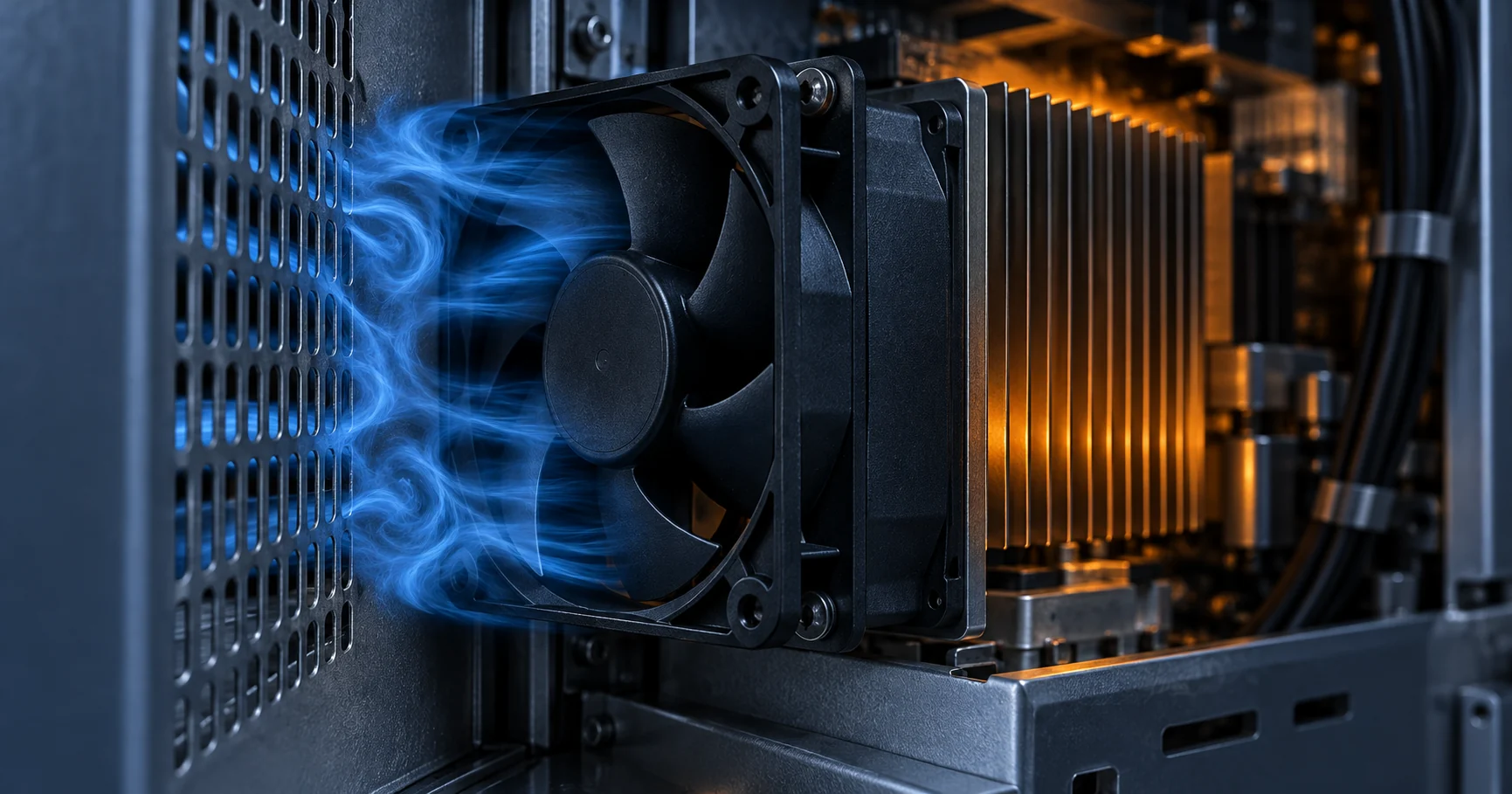
The fan curve was measured in a better installation than the product received
A cooling fan can meet its catalogue curve on a test rig and still miss the installed airflow when a wall, elbow, guard or abrupt outlet distorts the air immediately around it.
This is the fan-system interface problem engineers often discover late. The cooling fan is blamed because the cabinet runs hot, but the hidden loss may be created by the connection: the inlet is too close to a wall, an elbow sits directly at the inlet, a guard blocks the opening, or the outlet discharges into a tight plenum. The cooling fan then sees non-uniform or swirling flow instead of the uniform flow used for its rating.
The result is not only lower airflow. A distorted inlet can increase tonal noise, vibration and local loading, while a free or abrupt outlet can waste pressure recovery. The correct fix may be a clearance change, turning vane, inlet box, bellmouth, duct length or fan orientation rather than a faster motor.
The mechanism has a name and a published method behind it. System effect is the shortfall between catalogue performance and installed performance caused by the connection itself, and it appears whenever the airflow reaching the fan inlet is not fully developed, symmetrical and free of swirl, or the outlet is not given room to diffuse. AMCA Publication 201 treats that shortfall as a pressure term you add to the system resistance before you select a cooling fan. Aerovent's troubleshooting guide states the same rule from the field side: elbows belong at least three equivalent duct diameters upstream of a fan inlet, and duct fittings or installations that do not deliver smooth flow at the inlet, or full pressure recovery at the outlet, make the fan perform below its published rating.
That framing matters for compact electronics because the penalty is not a small correction. It is a term that can be larger than the pressure drop of the heat sink the fan is supposed to cool, and it is decided by the enclosure layout rather than by the fan part number.
The layout decisions that create it are the ones in the installation pitfalls we are asked about most often.

System effect is an additional pressure penalty at the fan interface
ASHRAE describes deficient fan and system performance as commonly arising from poor outlet connections, non-uniform inlet flow and inlet swirl. Greenheck's engineering guidance makes the practical comparison: fan ratings use defined AMCA test configurations, while elbows, walls, dampers, guards and abrupt transitions near the fan introduce losses that are easy to omit from a normal duct calculation.
Think of the penalty as an added term in the system curve. If the original system required 120 Pa at the target airflow and the installation adds an estimated 40 Pa of system effect, the cooling fan must now operate against roughly 160 Pa at that same airflow. The exact penalty is geometry and velocity dependent; the 40 Pa number is an illustrative calculation for this paragraph, not a universal allowance.
AMCA Publication 201 gives the penalty a shape rather than a rule of thumb. The System Effect Factor is a coefficient multiplied by the velocity pressure at the connection, so a penalty in pascals is the coefficient times one half of density times velocity squared. Because velocity pressure rises with the square of velocity, a connection that is already fast becomes disproportionately expensive when it is also crowded.
The magnitudes are concrete. In the worked factors accompanying Publication 201, one inlet configuration scores a coefficient of 0.40 and another scores 1.20 at the same velocity pressure of 124.5 Pa, so the two connections add 49.8 Pa and 149.4 Pa to the system from the same air. Publication 201 is explicit that these factors are approximations for the configurations tested, which is why the geometry has to be recorded rather than assumed.
| Value the method needs | Where that value comes from | What it changes in the answer |
|---|---|---|
| Fan type and connection | Centrifugal single or double width, tubeaxial or vaneaxial, and how it is connected | Which set of coefficient curves applies at all |
| Velocity at the connection | The cooling fan's own rated velocity at that inlet or outlet, taken from the catalogue | The velocity pressure the coefficient is multiplied by |
| Clear distance divided by inlet diameter | Measured from the wall, partition or plenum surface to the inlet plane | Which curve the coefficient is read from |
| Effective duct length fraction | Outlet duct length in diameters, against the effective length at that outlet velocity | How much pressure recovery is lost |
| Blast area divided by outlet area | The fan outline drawing, not the duct design drawing | The outlet coefficient for an abrupt discharge |
Inlet clearance is a ratio, not a distance
The most useful habit in this subject is to stop thinking in millimetres and start thinking in inlet diameters, because the airflow pattern around an inlet scales with its size. Thirty millimetres of clear space is generous in front of a 36 mm cooling fan and negligible in front of a 300 mm one, which is why the published curves are drawn against the ratio.
AMCA Publication 201 reads the coefficient for a cooling fan near a wall, partition or plenum surface from the ratio of clear distance to inlet diameter, with published values at 0.75, 0.50, 0.40 and 0.30. That is a steep range. The difference between three quarters of a diameter and one third of a diameter is not a small layout nicety, it is the difference between a connection that behaves close to the test rig and one that does not.
Greenheck's installation guidance uses the same logic for housed centrifugal cooling fans and states it as a minimum: keep at least three quarters of a wheel diameter between the fan inlet and the wall or bulkhead, and for a cooling fan inside a plenum keep the plenum walls at least half a wheel diameter away, with dampers or coils at least three quarters of a wheel diameter away so the velocity profile across them stays even. AMCA Publication 201 gives a matching rule for a different geometry, at least one impeller diameter of clear space between adjacent axial cooling fans in an array.
The numbers from a compact DC cooling fan are the ones most electronics engineers will actually use. SANYO DENKI tested a 36 mm square high-static-pressure fan against a flat sheet of metal on the inlet side and measured essentially no change in the pressure-flow characteristic at 30 mm, 20 mm and 15 mm of clear distance. At 10 mm the airflow performance started to fall away. Their recommendation is to keep inlet obstacles at least 15 mm from that cooling fan, which is a ratio of about 0.42 inlet diameters.
The two published figures, three quarters of a diameter and about 0.42 of a diameter, are not in conflict: they describe different fan sizes, different inlet geometries and different definitions of acceptable loss. The conclusion is that the ratio has to be chosen and recorded, not inherited from a previous project.
| Source | What it states | What it was written for |
|---|---|---|
| Greenheck installation guidance | Keep at least three quarters of a wheel diameter between an open inlet and the wall | Housed centrifugal cooling fans with an open inlet |
| Greenheck plenum guidance | Plenum walls at least half a wheel diameter away; dampers or coils at least three quarters | Cooling fans mounted inside an air plenum |
| AMCA Publication 201 | At least one impeller diameter of clear space between adjacent axial fans | Cooling fans arranged in an array |
| SANYO DENKI inlet test | Keep inlet obstacles at least 15 mm from this fan; measured loss began at 10 mm | A 36 mm square high-static-pressure DC cooling fan |
An obstruction near the inlet plane costs more than the area it blocks
A guard or a cable bundle rarely blocks the whole inlet. It blocks part of it, and the published method treats partial blockage as a distance-and-area problem rather than a simple area loss. AMCA Publication 201 reads an inlet obstruction coefficient from how much of the inlet area is left unobstructed and how far the obstruction sits from the inlet plane, with published unobstructed-area values of 100, 95, 90, 85, 75, 50 and 25 percent set against distances of 0.75, 0.50, 0.33 and 0.25 inlet diameters and the inlet plane itself.
Two things follow, and both are counter-intuitive in a tight cabinet. First, the penalty grows sharply as the obstruction moves towards the plane, so the same grille costs far more hard against the inlet than one diameter away. Second, a modest area reduction close to the plane can cost more than a severe reduction further away, because the flow has already reorganised itself by the time it reaches the inlet.
The extreme case is documented. Aerovent's troubleshooting guide describes a drop box at a centrifugal cooling fan inlet, where the inlet elbow is not a true elbow but a fabricated box, and notes that flow rate losses as high as 45 percent have been observed with that arrangement. It also warns that the loss for this geometry is nearly impossible to predict, because it depends on the fan type, the inlet size and the box width and depth together, and that an engineered inlet box with a predictable effect is the alternative.
Swirl deserves its own warning because it can hide. Pre-rotating swirl, where the ductwork spins the air the same way as the impeller, reduces the pressure the fan produces and the power it consumes, which looks like a benign efficiency gain while the flow falls. Counter-rotating swirl raises the pressure slightly and the power markedly. Neither shows on a static pressure gauge at the inlet plane.
The only reliable way to settle it is to measure the installation that ships, using the method set out in measuring airflow in a real enclosure, because a bench rig with an open inlet cannot reproduce the coefficient the enclosure applies.
The outlet wastes pressure recovery before it wastes airflow
The outlet side fails differently from the inlet side. A cooling fan leaves the impeller with a fast, asymmetric jet that still contains a large amount of kinetic energy. A straight run of duct lets some of that kinetic energy convert into static pressure, which is performance the system gets for free. Take the duct away and the conversion never happens; the fan still produces the velocity, but the static pressure it can push against the system drops.
AMCA defines the length over which that conversion completes as the effective duct length: a minimum of two and a half equivalent duct diameters for outlet velocities up to 2,500 feet per minute, with one further duct diameter added for each additional 1,000 feet per minute. Recovery is progressive rather than all-or-nothing. A duct of about 12 percent of the effective length realises roughly half of the available recovery, a quarter of the length realises about 80 percent, half the length about 90 percent, and only a full effective length realises all of it. No duct at all realises none.
The test standard is equally specific about the connection itself, which is useful as a design check even outside a laboratory. The outlet duct area is held between 95 and 105 percent of the fan outlet area, and any transition is limited to no more than 15 degrees of slope on a converging section and 7 degrees on a diverging section. A transition that is steeper than that is not a transition, it is a step, and it will show up as additional loss rather than additional pressure.
The required length depends on the fan type. A centrifugal cooling fan needs the full effective duct length to avoid system effect, while a vaneaxial fan needs about 50 percent. When a layout offers one duct length and two candidate fan types, the fan that tolerates less outlet duct may be the one that keeps the installed airflow.
| Outlet duct length | Share of recovery obtained | What the cooling fan loses |
|---|---|---|
| No duct, free discharge | Nothing | The whole velocity pressure is lost to the plenum |
| About 12 percent of effective length | About half | Roughly half the available static regain |
| About 25 percent of effective length | About 80 percent | The remaining fifth of the available regain |
| About 50 percent | About 90 percent | A tenth, which is the range a vaneaxial fan is rated for |
| 100 percent of effective length | All of it | Nothing measurable from the connection itself |
Guards, grilles and filters add resistance to the air path
A finger guard is a safety item that is also an aerodynamic component, and the published data treats it that way. SANYO DENKI's technical guidance on guards states plainly that guard geometry changes both maximum airflow and noise, that a smaller open area raises airflow resistance, and that the consequence of choosing a restrictive guard is a cooling shortfall and a noise level above expectation even though the cooling fan was correctly selected for the required airflow. Guards with 5 mm wide concentric openings, 5 mm punched holes and 4 mm slits do not perform the same, and the company's own guard range is presented as a low-loss option rather than a generic accessory.
The same logic applies to filters and filter kits. SANYO DENKI's filter kit range is offered in four mesh grades measured in pores per inch, 13, 20, 30 and 40, and the grade selection is a trade between dust-holding and pressure drop rather than a free choice. The practical point for an enclosure is that a filter which is clean at commissioning and loaded at month twelve changes the system curve, so the cooling fan has to be selected for the loaded condition, not the clean one. That shift is the subject of its own review in filter loading and the real fan operating point.
The engineering consequence is a rule about where the accessory is counted. Any element between the outside air and the impeller inlet, and any element between the impeller outlet and the room, belongs in the system resistance. Counting a guard, a grille or a filter as part of the enclosure rather than as part of the air path is the most common way a cooling fan ends up operating at a flow nobody predicted. The same rule applies to a heat sink fin stack, a cable bundle or a sheet metal lip that happens to sit in the inlet stream.
Clearance is a design variable, not leftover space
For an open inlet, the cooling fan needs enough space to draw air uniformly. Greenheck's published guidance uses one fan wheel diameter as a desirable straight or open distance in several common arrangements, and three quarters of a wheel diameter as the practical minimum; those are references for the described fan types and installation, not a universal rule for every compact DC cooling fan. In a tight enclosure, a smaller clearance can be acceptable if the inlet geometry, the guard and the performance are validated together.
The most expensive mistake is to reserve the cooling fan's frame envelope but not the airflow envelope. A 120 mm cooling fan may physically fit while the wall, cable bundle or stamped guard blocks much of the effective inlet area. Check free area, edge distance, grille thickness, mounting standoffs and the direction of the flow entering the impeller. In our own review of compact equipment, the frame outline is drawn correctly far more often than the inlet cone in front of it.
At the outlet, avoid placing a bend or a wall directly against the discharge unless the cooling fan and the connection were selected for it. A short straight section, an outlet cone or a better transition can recover useful performance without increasing speed. If space prevents an ideal connection, include the estimated system effect in the resistance curve and confirm it with a production-representative sample.
Treat the clearance as a number that appears in the drawing pack rather than a gap that happens to be left over after the boards are placed. Once it is written down, it can be reviewed, tested and defended; while it is implicit, it is the first thing a late mechanical change will consume.
| What to check | What to inspect | Evidence to collect |
|---|---|---|
| Inlet clearance | Wall, bulkhead, elbow, cable bundle and guard | Drawing or photo with dimensions and flow direction |
| Inlet uniformity | Swirl, obstructed area and abrupt transition | Velocity map or a representative flow test |
| Outlet connection | Bend, wall, plenum and discharge area | Pressure loss and operating-point measurement |
| Accessory restriction | Guard, filter, grille and damper free area | Pressure drop against airflow for each accessory |
| Sound behaviour | Tonal noise after installation | Sound measurement at the real operating point |
Two cooling fans in one opening: the spacing becomes the coefficient
Parallel cooling fans are the standard answer to a growing heat load, and the arithmetic behind them is the reason spacing policy matters. Two identical fans in parallel at the same pressure add their airflows, so the ideal array characteristic is simply the number of fans multiplied by the single-fan airflow. Real arrays do not reach that, because adjacent inlets interfere with each other, and the interference grows as the fans get closer.
The measurement is worth quoting because it is specific. SANYO DENKI tested a 36 mm square high-static-pressure fan as a single unit and as a pair mounted with zero distance between the frames, and measured 25 CFM for the single fan against 50 CFM for the pair, which is the ideal doubling. The same test measured no meaningful airflow penalty from an inlet obstruction at 30 mm, 20 mm and 15 mm and a reduction at 10 mm. A compact, high-pressure fan therefore tolerates a tight array far better than a large, low-pressure one, and the interference limit belongs to the fan and the pressure level rather than to a general spacing rule.
Where the array is axial and the pressure is significant, AMCA Publication 201 recommends at least one impeller diameter of clear space between adjacent fans, and the reason is the same inlet coefficient that governs a fan near a wall: a neighbouring fan inlet acts like a partial wall. Fan-array performance is also tested as an assembly rather than inferred from single-fan data, which is what ANSI/AMCA 270 covers, so an array claim should be supported by array data.
For a design review, decide the array geometry first, measure or model the assembly second, and only then decide whether the redundancy exists. An array that cools with every fan running tells you nothing about the array with one fan stopped, because the stopped fan is a leakage path rather than a wall.
Do not fix a connection problem by blindly increasing speed
If an installation delivers 20 percent less air, the intuitive response is to increase fan speed. The fan laws show why that can be expensive: for the same cooling fan, a 20 percent speed increase raises the idealized pressure capability by about 44 percent and the power requirement by about 73 percent, before motor, control and acoustic limits are considered. That is a calculation example based on the fan laws, not a promise that the installed system will recover the missing flow.
The published cost of a system effect is larger than most teams expect. In the worked example that accompanies AMCA Publication 201, a centrifugal cooling fan discharging directly into a plenum instead of through a short outlet duct has to overcome a calculated system effect, and the extra power required to overcome it is about 25 percent of the original system power, assuming the same fan can reach both operating points by a change in speed alone. A quarter of the fan energy budget, for a connection decision.
A connection redesign often protects more margin than a faster cooling fan. It can lower turbulence, reduce noise, keep the operating point away from an unstable region and preserve bearing and motor duty. If redesign is impossible, select the cooling fan from the corrected system curve and validate current, temperature, noise, vibration and airflow at the final speed.
There is a selection trap in the middle of this. A higher-pressure cooling fan in the same frame raises the pressure axis, so the same system effect costs less flow, which sounds like a clean answer, but it also raises power and noise and moves the operating point. The corrected curve is the only place where the comparison is honest.
| What to change | What it improves | What it costs |
|---|---|---|
| Redesign the connection | The added loss falls, so the operating point moves back up the fan curve | Layout or duct work, and the space it needs |
| Raise the speed by 20 percent | The installed flow returns on the corrected system curve | About 44 percent more pressure capability and about 73 percent more shaft power |
| Choose a higher-pressure fan in the same frame | A steeper curve, so the same added loss costs less flow | More power, more noise and a different operating point |
- Compare the cooling fan's catalogue test configuration with the actual installation.
- Add accessory and system effect losses to the system curve where they cannot be avoided.
- Check airflow, pressure, current, noise and vibration at the actual operating point.
- Use a production-representative sample before locking the enclosure geometry.
How to prove the installed operating point
System effect survives so long in product development because it is usually argued rather than measured. A connection is judged acceptable from a drawing, the first thermal test runs on a unit that happens to have a generous gap, and the penalty appears only when the enclosure is closed and the harness fitted. Measurement ends the argument, and it does not need a laboratory.
The minimum useful set is small. Static pressure at the inlet plane and at the outlet plane, taken with taps perpendicular to the surface and clear of the fast-moving stream, gives the pressure the cooling fan is actually working against. Airflow measured in the outlet duct gives the flow. Fan speed and supply current at the connector give the operating point on the curve. Component surface temperatures give the consequence that matters to the product.
Two disciplines make the record usable later. First, everything has to be logged against one clock and one configuration description, so a later change in guard, filter or harness can be compared with the original. Second, the worst case has to be stated explicitly, because the interesting condition is rarely the clean one: it is a loaded filter, a blocked inlet, a maximum ambient and a fan running on the corrected curve rather than the catalogue one.
When a test does not reproduce the catalogue curve, the comparison should be made against a system curve that includes the installation, not against the catalogue airflow. A shortfall that is expected and written into the design is a margin; the same shortfall discovered late is a redesign.
| What to measure | Where the measurement is taken | What makes the measurement usable |
|---|---|---|
| Inlet static pressure | At the inlet plane, tap perpendicular to the surface | Stated distance to the nearest obstruction in inlet diameters |
| Outlet static pressure | At the outlet plane, clear of the discharge jet | Same configuration and same fan speed as the inlet reading |
| Airflow | In the outlet duct, or by traverse where a duct is impossible | Instrument, calibration date and the method used |
| Speed and supply current | At the fan connector | Commanded duty cycle and the measured value together |
| Component temperature | At the worst-case component, not the average one | Ambient, soak time and the load case that produced it |
| Sound pressure | One metre from the inlet side of the cooling fan | Microphone position, background level and the mounting used |
From a corrected system curve to a validated production sample
A cooling fan is not selected for a catalogue number, it is selected for an operating point. At MEGA Tech we build custom DC and EC cooling fans, axial and backward-curved centrifugal, and the selection starts from the condition the fan will actually see: the required airflow, the static pressure at that airflow, and the installation effect the enclosure adds to both. That is a different conversation from choosing the largest frame that fits the opening.
In practice that means sizing a cooling fan against a corrected system curve rather than a clean one, proposing a connection change when the layout is the real constraint, and then demonstrating the result on the customer's own unit. A sample that meets a catalogue curve on a bench and misses the installed flow is not validated, so the acceptance test runs in the enclosure with the guard, filter, duct and heat source in place.
To do that we need a defined set of inputs from the project: the airflow required and the static pressure required at that airflow; the ambient and altitude basis the numbers were calculated at; the supply voltage and its tolerance; the control interface and the connector that must be used; the mounting envelope, including the clear distance in front of the inlet and behind the outlet; the acoustic target; and the life assumption the product has to meet. Where a value is not yet known, a bounded assumption is more useful than an empty cell, because it can be tested.
Our boundary is equally worth stating plainly. We supply the cooling fan and the fan-side connection review. We do not supply coils, liquid cooling loops, drive controllers, cabinet safety design or emergency ventilation systems, and we will not certify a layout we have not seen. We also do not accept that the same outline dimensions make two cooling fans equivalent: the frame can match and the curve, the bearing system, the acoustic signature and the life at temperature can all differ, and the installation effect is exactly the kind of difference that a dimensional comparison hides.
Clearance should be specified as part of the released assembly
Clearance is not a decorative dimension around a fan. An obstruction close to the inlet or outlet can create a separated flow region, increase turbulence and move the operating point away from the catalogue condition. Define the clearance from the fan face to the nearest grille, cable bundle, wall or heat sink, and keep the dimension tied to the mounting datum. If the service door, filter frame or harness can move, record the worst credible position rather than the nominal CAD spacing.
Validate the released clearance with pressure and temperature measurements. A smoke or tufts check can show a recirculation loop, but it should lead to a quantitative test rather than replace one. Repeat after tightening the mounting, changing the gasket or routing the cable, because each change can alter both vibration and resistance. If space cannot be increased, consider the air-path correction, a different fan type or a validated pressure target; do not compensate by adding speed without checking noise, power and bearing temperature. The sample-validation checklist provides a record structure.
Engineer FAQ: fan installation effect in compact equipment
The cooling fan is only one part of the aerodynamic assembly.
Q: Why does a cooling fan meet the data sheet but fail in my cabinet? A: The rating applies to a defined test installation. Nearby walls, elbows, guards, filters and abrupt transitions add pressure loss and distort the inlet or outlet flow, so the installed operating point sits further down the fan curve than the catalogue point.
Q: Is one fan diameter of clearance always mandatory? A: No. Three quarters of a wheel diameter appears as a minimum in published guidance for housed centrifugal fans, and a compact 36 mm DC fan showed no measurable loss until the obstruction came within 10 mm. The correct clearance depends on fan type, geometry, guard, speed and the required operating point, so validate the actual compact assembly.
Q: Can I simply choose a higher static-pressure cooling fan? A: Sometimes, but first check whether the connection is creating avoidable turbulence. A higher-pressure fan may raise power, noise and vibration while hiding the underlying layout problem, and it will move the operating point rather than remove the penalty.
Q: Does a guard count as system resistance? A: Yes. Its free area, wire geometry and distance from the cooling fan affect both the pressure loss and the uniformity of the flow entering the impeller, and the published guard data shows that guard shape changes both maximum airflow and noise.
Q: How much does an abrupt outlet discharge actually cost? A: It removes pressure recovery rather than airflow directly: with no outlet duct, none of the velocity pressure converts back to static pressure, and a quarter of the effective duct length realises about 80 percent of it. In the AMCA Publication 201 worked example, recovering that deficit by speed alone cost about 25 percent of the original system power.
Q: How do I decide between fixing the layout and changing the fan? A: Put the installation effect into the system curve first, then compare. If the corrected curve still gives the required flow with margin, keep the fan and fix nothing. If it does not, the comparison shows how much pressure has to be found and whether a different fan or a different connection is the cheaper way to find it.
Q: Do the relationships between speed, airflow and pressure still apply after a layout change? A: Yes, but only on the corrected curve. Airflow still scales with speed, and pressure with the square of speed, for the same cooling fan, so those relationships tell you how the operating point moves; they do not tell you where it starts, and that is what the installation decides.
Q: What should a sample test prove? A: Test the cooling fan in the real mounting, guard, grille, filter, duct and heat-source arrangement. Record airflow, pressure, current, speed, component temperature, noise and vibration at clean and worst-case conditions, and state the clear distances that were present when the readings were taken.
Q: What clearance value should I copy from another fan installation? A: Do not copy a universal value. Define the obstruction, flow direction, grille and pressure duty, then validate the actual released geometry.
Q: Does increasing fan speed always fix a tight inlet? A: No. It can increase noise, power and vibration while leaving a separated or recirculating path. Measure the pressure and thermal result before deciding.
Questions for a Design Review
Five questions that turn a layout argument into a recorded design decision.
- What is the clear distance in front of the inlet, expressed in inlet diameters, and what is the nearest obstruction?
- What is the outlet connection, how long is the straight section, and how much pressure recovery does the layout actually realise?
- Which accessories sit in the air path, and does the cooling fan selection use their loaded pressure drop rather than their clean one?
- Is the array, if there is one, supported by assembly data rather than by single-fan data multiplied by the number of fans?
- What is the measured installed operating point, at the worst case, in the configuration that will ship?
