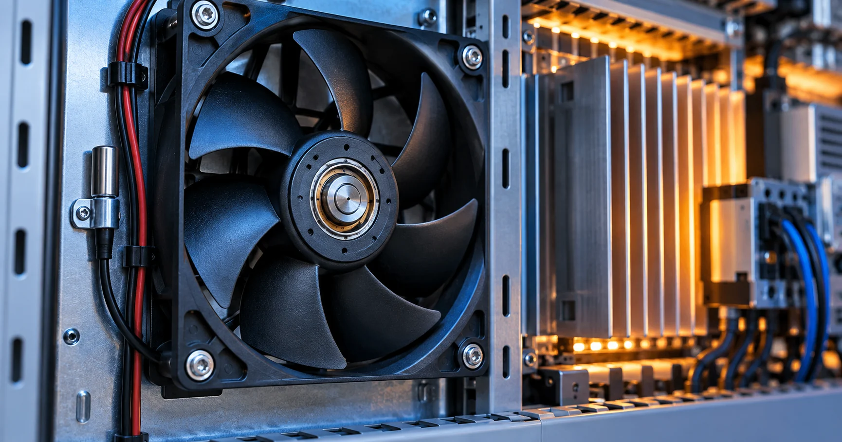
Why a cooling fan can disturb the system
A fan can meet the airflow target and still create an electromagnetic compatibility problem after it is connected to a real controller, harness and enclosure.
The fan is an electromechanical load. Its driver commutates motor windings, its control input may be switched, and its current changes whenever the rotor accelerates, decelerates or encounters a different air-path load. Those transitions can couple into the supply, the control cable, the chassis or nearby signal circuits. The disturbance may appear as a sensor error, a radio desense event, a failed emissions scan, an unstable tachometer signal or an audible tone that is actually being produced by an electrical sideband.
The right engineering question is not whether a fan is intrinsically noisy. It is whether the fan, controller, harness, mounting and enclosure form an acceptable system at the intended operating point. A bench test with a short cable and a clean laboratory supply can hide the return-current path that exists in the production assembly. A fan behind a filter or heat sink also draws a different current waveform from one running in free air.
This article is an educational design method. It explains common EMI paths, what standards such as EN 55032 and the CISPR family are intended to describe, and which questions a system designer should ask a fan supplier. It does not certify any MEGA Tech product or replace the compliance plan for the finished equipment.
1. Conducted and radiated EMI are two different paths
Conducted disturbance travels through a conductor. In a cooling system that may be the DC supply, the return conductor, a PWM control wire, an FG or RD signal, a protective earth connection or a shared harness to another board. A current edge at the fan can therefore appear as voltage ripple at a controller, converter or sensor even when the fan is physically several centimetres away.
Radiated disturbance couples through space or through the structure. The fan cable can behave as an antenna, a large panel can become a receiving or radiating surface, and a fast current loop on the controller PCB can couple to a nearby clock, RF trace or analogue measurement. The distinction is useful for diagnosis, but the same physical design may produce both forms. A conducted problem can excite a cable that then radiates, while a radiated field can enter a cable and return through the power system.
Separate the test plan into differential-mode and common-mode questions. Differential-mode current flows out on one conductor and returns on another. Common-mode current moves together on several conductors relative to chassis or earth. The filter, cable geometry and measurement arrangement need to match the mode being investigated. A ferrite that helps one mode at one frequency is not evidence that the complete harness is controlled.
| Observation | Likely path to investigate | Useful evidence |
|---|---|---|
| Supply ripple changes with fan speed | Conducted differential-mode current | Fan-pin voltage, current probe and converter waveform |
| The fault follows cable position | Radiated or common-mode coupling | Cable reroute, chassis reference and near-field scan |
| Only PWM duty steps trigger the fault | Control edge, commutation or return-current path | PWM at fan connector, FG/RD and synchronized scope capture |
| A radio or sensor fails only after installation | System-level coupling and enclosure resonance | Production harness, panel, grounding and worst-case operating point |
2. PWM switching and motor commutation create edges
A PWM-controlled fan contains at least two switching events worth separating. The external PWM control input changes state according to the command frequency and duty cycle. Inside the fan, the electronic driver commutates the motor windings. Both events can create fast voltage or current transitions, but their timing and amplitude are not necessarily the same.
A four-wire PWM fan normally keeps the supply within its specified range and uses a separate control input. Chopping the entire supply with a low-side MOSFET is a different interface: the driver repeatedly loses power, the FG/RD reference can move, and the harness sees larger current edges. It may still spin, but the electrical behaviour is no longer the same as the intended control method. Always confirm the fan pinout, input threshold, pull-up arrangement, allowed frequency and minimum stable duty at the fan connector.
Do not assume that moving the carrier above the audible band solves EMI. A carrier can mix with commutation, create sidebands or excite a panel. Conversely, a slower carrier may make acoustic modulation obvious while reducing some edge losses. Sweep a permitted control range while holding voltage, airflow and pressure constant, then measure both the electrical spectrum and the thermal result. A control change is only useful if it leaves the installed operating point valid.
For a first technical reference, the Microchip EMC2301 documentation shows how a fan controller treats speed control and monitoring signals. It is a controller reference, not a certification or a guarantee for any particular fan.
3. Why fan cables become antennas
A cable becomes more effective at coupling when its length, loop area, termination and proximity to other conductors support the disturbance frequency. A pair with closely coupled outgoing and return paths usually presents less loop area than two separated wires. A cable that runs along a chassis or crosses a sensitive analogue trace can create a different result from the same cable coiled beside the fan.
Keep the power and return conductors together where practical, and route the PWM signal with its intended reference rather than borrowing a distant noisy return. Avoid long parallel runs beside antenna, sensor or high-impedance analogue wiring. If a shield is used, define where it terminates and what current it is expected to carry; an unplanned pigtail can add inductance and create a new coupling point.
Connector choice matters too. A connector can place the signal next to a switching supply pin, expose a long unreferenced contact or introduce a large loop at the board edge. Capture the voltage at the fan-side connector, not only at the MCU. If the cable is changed between prototype and production, repeat the EMI screen because length, twist, shield and connector geometry are part of the system.

4. PCB layout controls the return current
The forward trace does not define the complete circuit; the return path does. Place the fan connector, switching device, protection components and bulk capacitance so the high-current loop is compact. Keep the fan-current return from sharing a narrow section of ground with a sensor reference, oscillator, ADC input or communication transceiver. A split ground plane is not automatically better: an unintended gap can force current around a sensitive circuit and increase the loop area.
Use the schematic to identify the current that changes during startup and commutation. Then inspect the physical loop on the PCB. A wide trace alone cannot solve a poorly placed return path. Put decoupling close to the switching or connector entry point, verify that the selected capacitor remains effective at the relevant frequency, and consider the DC drop and startup pulse as well as the high-frequency impedance.
A gate resistor, series signal resistor or controlled edge rate can reduce ringing and overshoot, but it also changes timing and may affect the fan input. Test the full voltage and frequency range. Do not place a large capacitor directly on a PWM input without checking the controller's drive capability, rise time and minimum-high/low requirements. The goal is a defined interface, not simply a slower edge.
5. Filtering, shielding and grounding choices
Filtering works when its impedance, placement and current rating match the disturbance. A common-mode choke is intended to impede common-mode current while allowing the desired differential current to pass. A differential LC or ferrite arrangement addresses a different path. A capacitor from a noisy node to chassis can help only when the chassis connection is short, controlled and allowed by the safety and insulation design.
Place the filter where the disturbance enters or leaves the protected zone. A filter installed far from the connector can leave an unfiltered trace or cable acting as an antenna. Keep the noisy side and clean side physically separated; otherwise the filter may be bypassed by capacitive or inductive coupling. Check the DC resistance, temperature rise, saturation, startup current and fan control waveform after the filter is installed.
Shielding is not a substitute for a defined return path. Bond a metal enclosure according to the equipment design and safety requirements. If the fan frame is isolated with a gasket, decide whether that is intentional for vibration, electrical isolation or both. Measure the result with the production panel, fasteners and cable route. EMC improvements that depend on a loose prototype ground clip are not production evidence.
The FDA's electromagnetic compatibility guidance for medical devices is a useful reminder that EMC belongs to the finished device and its intended environment. It is not evidence that a fan component is certified.
6. What EN 55032 and CISPR-style tests actually cover
EN 55032 specifies electromagnetic disturbance characteristics for multimedia equipment and is used within a product's applicable compliance framework. It is not a generic cooling-fan certification. The relevant limits, ports, detectors, test site and configuration depend on the equipment category and the applicable edition or national adoption. CISPR publications similarly describe measurement and limit frameworks for defined product families; they do not turn every component into a universally approved device.
IEC 61000 documents cover several EMC topics, including immunity, test methods and environment-related practices. A system designer may need to consider conducted emissions, radiated emissions, electrostatic discharge, electrical fast transients, surge, radiated RF immunity and other tests depending on the equipment and market. The fan can influence these tests, but the equipment maker must define the applicable requirements and test configuration.
Keep three statements separate in purchasing documents: a standard that the equipment is assessed against; a supplier's component-level test report or screening result; and a formal certification or declaration that applies to a specific product, model, market and configuration. Do not copy a standard name into a fan title and imply that the fan itself has passed the finished-equipment test.
Before a test house visit, freeze the cable route, fan count, control software, supply, enclosure, load and operating point. A compliance test is not meaningful if the tested assembly differs from the released assembly.
| Statement | What it means | What it does not prove |
|---|---|---|
| The equipment is assessed to EN 55032 | The declared equipment test plan uses that requirement where applicable | That an individual fan is certified to EN 55032 |
| A fan sample had an internal EMI screen | A defined sample and setup produced recorded observations | That every system configuration will pass emissions |
| The supplier provides interface data | Pinout, control limits, current and sample evidence are available | That the equipment maker's chassis and PCB are compliant |
| The released system passed its applicable EMC tests | The tested product configuration met the declared criteria | That an untested replacement fan or cable will behave identically |
7. A practical bench-to-system troubleshooting sequence
First freeze the thermal baseline. Measure component temperature, fan inlet temperature, airflow, static pressure, RPM and current at the worst planned condition. Include the filter, grille, heat sink, duct and cable bundle that will ship. The quietest or cleanest EMI result is not a pass if the equipment overheats.
Second create an electrical baseline at the fan connector. Capture supply voltage during startup and steady operation, PWM amplitude and frequency, FG/RD waveform, current and the relevant scope bandwidth. Repeat with the controller disabled, with a reference harness and with the production harness. Label each condition so a later change can be attributed to one variable.
Third classify the symptom. Does it move with fan RPM, PWM frequency, duty cycle, cable position, panel contact or another load switching nearby? A peak that follows RPM may be mechanical or commutation-related. A peak that follows PWM frequency suggests a control or switching path. A symptom that appears only when the panel is installed suggests structure or chassis coupling. These are screening observations, not final proof.
Fourth change one variable at a time: cable pairing, return route, filter position, edge rate, PWM frequency, shield termination, mounting isolation or chassis bond. Repeat thermal, electrical and acoustic checks after each change. Finally run the production-representative assembly, including multi-fan operation, fault recovery, hot start and the intended service configuration.
When an external laboratory is involved, send a configuration record with the sample. Include hardware revision, fan model and revision, number of fans, supply and converter, firmware, cable and connector, filter, chassis panels, load condition and software state. Note whether the fan is controlled at a fixed speed, by temperature, by a protection loop or by a communication command. This prevents a passing setup from being recreated with a different control state.
A useful failure report contains the frequency or symptom, the operating condition, the measurement location, the instrument bandwidth and probe arrangement, the change that affected it, and the thermal result after the change. A statement such as 'the ferrite fixed EMI' is not enough: identify which cable, which mode, which frequency range, which current and which production placement. The evidence then remains useful when the supplier, PCB or enclosure changes.
8. Questions to ask the fan supplier
Ask for the exact pinout and interface definition: supply range, PWM input reference, input threshold, permitted frequency and duty range, FG or RD electrical behaviour, pull-up requirements and connector options. Ask whether the published current is measured at free air or at a defined operating point, and whether startup current is recorded separately.
Ask what evidence exists for the complete fan and what is only a component datasheet value. Useful evidence can include a wiring diagram, current waveform, control-interface description, sample configuration, cable length, mounting condition, internal screening method and any limits observed during development. The supplier should distinguish measured data from an engineering target.
Ask how a proposed change will be controlled. A different driver, PCB revision, bearing, connector, cable, firmware setting or motor winding can change the electrical signature. Confirm what requires re-sampling and what information will be included in the approval record. A supplier cannot determine final system compliance from a part number alone, but it can make the interface and sample evidence traceable. Ask the same questions for a nominal replacement and for a custom revision; the approval boundary should be visible to purchasing, quality and service teams.
9. MEGA Tech custom fan development and scope boundary
MEGA Tech develops and manufactures custom cooling fans through fan selection, air-path review, sample validation and volume production. For an EMI-sensitive project, provide the frame and thickness, voltage and tolerance, airflow and static-pressure target at that airflow, speed or PWM range, FG/RD requirement, connector, cable length, mounting, temperature, noise limit and environment.
We can review the fan interface with the customer's controller, compare a sample in the representative air path, and keep the approved configuration traceable for production. The right output is a measured sample and an agreed interface, not a generic statement that one fan type will solve every EMC problem.
The system integrator remains responsible for the complete equipment EMC plan, PCB layout, converter, shielding, chassis, software, final test configuration and market compliance. MEGA Tech does not claim that a fan alone passes EN 55032, CISPR or IEC 61000, and this article is not a product certification statement.
10. Engineer FAQ
Q: Is a PWM fan automatically EMC compliant? A: No. PWM compatibility describes an interface requirement. The finished system still depends on the fan driver, controller, harness, PCB, chassis, mounting and applicable test plan.
Q: Should I switch the fan supply with a MOSFET to control speed? A: Only if the selected fan and system interface are designed for that method. Removing power repeatedly can change startup, FG/RD and current behaviour. Check the intended control method first.
Q: Can a ferrite fix every fan EMI problem? A: No. It may reduce a measured conducted path when selected for the relevant current and frequency. It cannot fix a blocked air path, unstable control input, poor return loop or chassis coupling.
Q: Does EN 55032 certify the fan? A: No. It defines disturbance requirements for applicable multimedia equipment. Whether it applies, and how, belongs to the equipment compliance plan.
Q: What is the most useful first measurement? A: Measure voltage and current at the fan connector while capturing PWM, FG/RD and the symptom synchronously. Also record airflow and static pressure so the electrical change is not hiding a thermal failure.
Q: Why does the fan pass on the bench but fail in the cabinet? A: The cabinet adds cable length, return paths, panel resonance, filters, grilles, heat sinks, software sequencing and nearby switching circuits. Re-test the production-representative assembly.
Q: What should a custom sample request include? A: Frame, thickness, voltage, airflow, static pressure, PWM/FG/RD, connector, cable, mounting, environment, noise limit and the system condition where the symptom occurs.
11. Questions for a Design Review
- What applicable EMC requirements and product standards govern the finished equipment in each target market?
- Is the fan using the intended supply and control interface, with the reference defined at the fan connector?
- What are the fan-pin voltage, startup current, steady current and PWM waveform at the worst operating point?
- Are differential-mode and common-mode paths identified separately in the schematic and harness drawing?
- Where does the fan-current return flow, and does it share impedance with a sensor, clock, RF or communication return?
- Does the symptom track RPM, PWM frequency, duty cycle, cable position, panel installation or another switching load?
- Has the filter been checked for placement, current, startup behaviour, control waveform and thermal rise?
- Are shield and chassis terminations defined for the production enclosure rather than a temporary bench lead?
- Has the complete assembly been tested with the production fan, cable, controller, software, filter, grille and mounting?
- Which supplier data is measured, which is a target, and which change would trigger a new sample validation?