
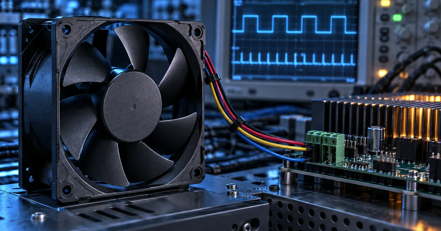
When a PWM fan becomes the noise source
A fan that cools correctly on the bench can whistle, click or inject a repeating disturbance into the product after it is connected to the real controller. The first job is to separate an acoustic problem from an electrical one.
The symptom usually arrives in one of three forms. The operator hears a narrow whistle that changes when the PWM command moves. The control board sees a wandering tachometer signal or a reset when the fan starts. Or an oscilloscope shows a clean-looking speed command while the 12 V or 24 V rail carries a burst of ripple at the same time the fan changes speed. These symptoms are related, but they are not the same failure.
A useful diagnosis begins with the installed operating point, not with the word PWM. Record the fan voltage at its connector, the current during start and steady state, the PWM frequency, the duty-cycle range, the FG or RD waveform, the airflow and the static pressure at the selected point. Also record the microphone position and the enclosure state. Without these details, a change from 30 percent to 40 percent duty is not a reproducible test condition.
The practical rule for this article is simple: do not solve a mechanical tone with a filter, and do not solve a supply disturbance by changing the blade geometry first. Trace the symptom through three paths—power, control and structure—then change one path at a time. That keeps the thermal requirement intact while the noise or EMI cause is being isolated.
What engineers are actually trying to fix
Forum questions about PWM fan noise repeat the same design-review problems: the control frequency is audible, the fan is being driven through the wrong interface, or the supply and signal return are sharing a noisy path.
An Electronics Stack Exchange question about eliminating PWM noise while driving a fan focuses on the familiar high-pitched sound that appears only at some command values. Other highly rated questions deal with a noisy 12 V rail, a three-wire versus four-wire fan connection, and a 12 V fan connected to a 24 V supply. These are not isolated hobby problems; they are the same integration mistakes that appear when a production controller is designed around a catalogue label instead of an interface specification.
The first distinction is between a four-wire PWM fan and a fan whose supply is being chopped by a MOSFET. In a four-wire interface, the supply should remain within the fan's specified range while the separate control input carries the speed command. Low-side switching of the whole supply can create a different electrical environment: the internal driver repeatedly loses power, the tachometer reference moves, and the current edges become much harder for the harness and PCB to contain.
The second distinction is between the PWM carrier and the acoustic result. A carrier above the audible band can still create an audible sideband through motor commutation, magnetic force, a nonlinear controller input, or a panel resonance. A command below the minimum stable duty can also make speed hunt. Therefore the test must sweep frequency and duty at the real voltage and load rather than declaring the interface quiet because the nominal PWM frequency is ultrasonic.
The design-review output should be a small evidence pack: a wiring diagram, the connector pinout, voltage at the fan, supply ripple, PWM frequency and amplitude, FG/RD capture, sound spectrum and thermal result. That pack is more useful than a single statement that the fan is PWM compatible.
The three paths: power, control and structure
A repeatable diagnosis follows the energy from the controller to the fan, from the signal pin into the driver, and from the motor into the enclosure.
The power path includes the converter, protection device, connector, cable and return plane. Measure directly at the fan pins, not only at the power supply terminals. A long harness can turn a clean 24 V source into a rail with a short voltage sag during startup and a burst of ripple during commutation. Measure at no load, at the normal operating point and during the first 500 ms after the fan is enabled. If the trace is difficult to capture, use a short ground spring or a differential probe; a long oscilloscope ground lead can manufacture a ringing waveform.
The control path includes the PWM output stage, pull-up or pull-down, cable capacitance, connector, fan input and signal return. Record the high and low voltage at the fan, the rise and fall time, the frequency, the duty cycle and the reference used by the controller. A command that looks correct at the MCU pin may not be correct at the fan after a protection resistor, optocoupler, cable and shared return have been added.
The structure path includes the fan frame, gasket, screws, bracket, panel and any cable that can bridge the mount. If the noise peak remains at the same frequency while the PWM frequency changes, suspect a shaft, blade-pass or panel mode. If the peak follows the command or appears at a switching sideband, suspect the drive or power path. This is a screening rule, not a substitute for a spectrum measurement.
Do not change all three paths at once. A ferrite added to the supply, a new PWM frequency and a softer mount can make the symptom disappear without revealing why. That may be acceptable for a prototype, but it leaves the production margin unknown.
| Observed change | Most likely path | Next measurement |
|---|---|---|
| Tone moves with PWM frequency | Control or drive sideband | Sweep frequency while holding duty, voltage and pressure constant |
| Tone stays fixed while duty changes | Blade pass, bearing or panel resonance | Measure RPM and one-third-octave spectrum |
| Rail dips when fan starts | Power path or current limit | Capture fan-pin voltage and current during startup |
| FG/RD becomes unstable only in the product | Signal return, pull-up or EMI coupling | Probe at the fan and controller ends together |
| Noise changes after tightening screws | Structure or transmission path | Repeat with defined torque and gasket condition |
PWM frequency: move the carrier, not the requirement
Changing frequency can move an audible component, but it cannot compensate for an incorrect interface, an unstable duty range or a fan that is operating at the wrong pressure point.
The PWM input is a command, not a promise that every frequency and duty combination will produce the same speed. Manufacturer guidance must be checked for the selected family. For example, SANYO DENKI technical material describes a 25 kHz PWM input for the referenced San Ace PWM interface and warns that speed can become unstable below roughly 20 percent duty on the illustrated models. Those values are a reference for the cited family, not a universal MEGA Tech specification.
Use a frequency sweep to find a quiet and stable region. Keep the supply voltage, airflow restriction and average duty constant while testing, for example, 1 kHz, 5 kHz, 15 kHz, 25 kHz and the controller's proposed production value. At each point record RPM, current, FG period, acoustic spectrum and temperature. Reject a frequency if the speed hunts, the FG waveform becomes intermittent, the rail shows excessive edge energy or a narrow audible line appears.
Do not lower the carrier merely because the fan sounds quieter at one duty. A low-frequency command can create a modulation envelope that is more objectionable than a higher carrier, while a high-frequency edge can increase conducted or radiated EMI if the rise time is aggressive. The correct change may be a controlled edge rate, a defined pull-up, a shorter return path or a different input interface rather than a new carrier.
A production control curve should also define the minimum command. If the thermal design needs a low standby speed, validate that speed directly. If the fan is unstable below a family-specific limit, use an approved minimum duty, burst-to-start sequence or another control strategy that has been tested with the actual fan. Never assume that zero-to-100 percent duty is a safe operating map.

Supply ripple, grounding and the harness
Many apparent PWM problems are supply or return-path problems. The fan sees the voltage and reference presented at its connector, not the ideal schematic source.
Start with the voltage tolerance and current capability of the selected fan. An overvoltage event is not a control experiment; it can damage the internal driver. A 12 V fan on a 24 V rail must be corrected with the power architecture, not made acceptable by reducing PWM duty. The same applies to a 24 V fan fed by a converter whose output collapses during multi-fan startup.
Measure ripple with bandwidth limits documented. Capture the rail with the fan off, at steady operation, during a duty step and during a simultaneous start of the number of fans the product can command. Compare the waveform at the converter, controller and fan connector. If a filter improves the waveform at the controller but not at the fan, the harness or return path is still the problem. If the filter reduces ripple but raises startup time or causes the converter to oscillate, the thermal fix has created a system-level fault.
Keep high-current motor return paths away from sensitive tachometer and PWM returns where the layout allows. A star connection is not automatically better; the important point is to define where the signal reference and power return meet, and to keep the high di/dt loop compact. Cable shield, chassis bond and connector pin order should be treated as part of the EMC design, not as an afterthought after the first acoustic test.
Ferrites and capacitors are useful when their impedance is appropriate for the measured disturbance. They are not substitutes for a scope capture. Select the component against the frequency content and current, then repeat the thermal, startup and fault-signal tests. A cleaner rail that slows the fan's response or clips the FG waveform is not a successful repair.
| Item | Record | Pass/fail question |
|---|---|---|
| Fan-pin voltage | Nominal, minimum and maximum during startup and duty steps | Does it remain inside the selected fan's rated range? |
| Current | Startup peak, steady current and multi-fan total | Can the converter and protection device support the transient? |
| PWM | Frequency, high/low voltage, duty and edge time at the fan | Is the command inside the fan-family interface limits? |
| FG/RD | Frequency, amplitude, pull-up and missing-pulse behaviour | Can the controller distinguish speed from noise? |
| Rail spectrum | Ripple and narrow peaks with bandwidth stated | Does the disturbance coincide with the acoustic or control symptom? |
Separate electrical sound from mechanical sound
A microphone and an oscilloscope answer different questions. Use their timing and frequency relationship to decide whether the next change belongs in the circuit or the fan mount.
A narrow acoustic line that follows PWM frequency or one of its sidebands points toward the drive, supply or control path. A line that follows RPM points toward blade-pass excitation, bearing behaviour or an air-path tone. A line that remains fixed while both PWM and RPM move points toward a structural mode or an external source. These relationships are more informative than the total dBA number alone.
For the mechanical check, record RPM and calculate the blade-pass frequency from blade count times revolutions per minute divided by 60. Mark that frequency and its harmonics on the one-third-octave spectrum. Then repeat with the fan on the production bracket and with a temporary soft interface. If the line falls when the transmission path is interrupted, the fan may be acceptable and the enclosure needs work. If the line remains at the fan frame, review the operating point, balance, bearing and selected geometry.
For the electrical check, trigger the oscilloscope from the PWM edge and observe the fan-pin rail, the PWM input and FG/RD on separate channels. Look for a rail step synchronized with the edge, a delayed tach transition, ringing at the connector or a duty-dependent burst. Repeat with the PWM source disconnected and the fan commanded by the reference method. The comparison shows whether the controller or the fan-side interface introduces the disturbance.
The result should name the mechanism, not only the symptom: for example, 'a 7.2 kHz tone appears at the PWM sideband when the fan is at 38 percent duty against 1.4 mmH2O, while the panel mode remains unchanged.' That sentence gives the next engineer a condition to reproduce and a path to verify.
A validation sequence that does not disturb thermal performance
The quickest route is a controlled sequence: establish cooling, characterize the interface, isolate the mechanism and then confirm the fix at the worst-case duty point.
First, freeze the thermal baseline. Measure component temperature, inlet temperature, outlet temperature, airflow, static pressure, RPM and current at the hottest planned operating condition. Include the filter, grille, heatsink, duct and cable bundle that will ship. A noise fix that lowers airflow or increases component temperature is not a pass.
Second, create an interface baseline with the fan mounted as intended. Capture supply voltage, startup current, steady current, PWM frequency and amplitude, FG/RD waveform and the acoustic spectrum at several duty points. Use the same controller and harness intended for production. If the prototype uses a bench supply or temporary jumper, label those results as screening data.
Third, change one variable per run. Suggested runs are: reference wiring; corrected four-wire wiring; clean supply return; alternate PWM frequency; controlled edge rate; temporary isolation; and corrected inlet clearance. At each run repeat the same thermal and electrical captures. A small test matrix prevents an attractive but unrepeatable improvement from becoming the production design.
Fourth, test the boundaries: cold start, hot restart, minimum stable duty, maximum pressure point, simultaneous fan start, controller fault response and the intended service condition. For a multi-fan product, check beat tones and FG identification when two fans run at slightly different speeds. Record the pass condition in the design file, not only in the engineer's notebook.
Finally, validate the production-representative assembly. Use the customer's mounting torque, gasket, connector, cable route, enclosure panel and airflow restriction. Measure at the operator or bystander position defined by the product requirement, and report the room, distance, weighting, background and spectrum method.
| Step | Hold constant | Evidence to keep |
|---|---|---|
| Thermal baseline | Fan, enclosure and controller | Temperature, airflow, pressure, RPM and current |
| Interface baseline | Mounting and air path | Fan-pin voltage, PWM, FG/RD, current and spectrum |
| Single-variable isolation | Operating point and measurement position | Before/after trace for one changed variable |
| Boundary test | Production wiring and software | Start, minimum duty, fault and multi-fan captures |
| Final sample | Customer assembly and fixture | Signed thermal, acoustic, EMC-screening and control results |
Engineer FAQ: PWM fan noise and EMI
The following answers are intended to prevent a common mistake: treating a control-interface symptom as proof that the fan geometry is wrong.
Q: Can I make a fan quiet by lowering PWM duty? A: Often, because speed and acoustic output fall together, but only if the fan remains above its minimum stable duty and the airflow and pressure requirement are still met. Measure the installed operating point rather than relying on duty alone.
Q: Should I always use a high PWM frequency? A: No. Use the frequency range specified for the selected fan family, then test the actual controller, harness and mount. A high carrier can move audible energy away while increasing edge-related EMI.
Q: Why is the fan quiet on a bench supply but noisy in the product? A: The product may add supply ripple, a different signal reference, a long harness, a close inlet obstruction or a resonant panel. Reproduce the product wiring and pressure point before judging the fan.
Q: Can a ferrite solve the problem? A: It can reduce a measured conducted disturbance when selected for the relevant frequency and current. It cannot fix a blocked inlet, unstable minimum duty or a panel resonance, and it must be rechecked for startup and FG/RD behaviour.
Q: What should I send for a custom sample? A: Send the frame and thickness, voltage tolerance, airflow and static-pressure target at that airflow, PWM frequency and duty range, FG/RD requirement, connector, clearance, mounting detail, noise limit and environment. A sample is useful only when it is tested in the representative assembly.
Questions for a Design Review
Use these questions before changing the fan model or signing off a PWM interface.
- Is the selected fan being driven through its intended four-wire interface, with supply and PWM reference defined at the fan connector?
- At the required airflow and static pressure, what are the minimum and maximum stable PWM duties and the corresponding RPM values?
- Does the measured fan-pin voltage remain within the rated range during simultaneous startup, duty steps and fault recovery?
- Does the FG/RD signal remain valid with the production pull-up, cable, connector and return path?
- Which acoustic peaks track PWM frequency, which track RPM or blade-pass frequency, and which remain fixed?
- Has the test included the real filter, grille, heatsink, cable route, panel and mounting torque?
- Has the design been checked at the thermal worst case, not only at the quietest laboratory condition?
From a PWM complaint to a validated fan sample
MEGA Tech develops and manufactures custom cooling fans—from fan selection, air-path review and sample validation to volume production. We can work from a required frame and thickness, voltage, airflow, static pressure, speed, PWM command, FG or RD output, connector, bearing and environment. Selection is based on the installed operating point rather than on a part number or an outline-size comparison.
For a noise or EMI investigation, the useful starting package includes the fan size, voltage tolerance, airflow and static pressure at that airflow, PWM frequency and duty range, controller output, FG/RD requirement, connector and cable length, mounting and inlet clearance, acoustic limit and measurement position, temperature, altitude, dust or moisture exposure and life assumption. We can then identify which data still needs to be measured on the customer's assembly and arrange a representative sample validation.
Our scope is the custom cooling fan and its engineering validation. The complete cabinet, heat exchanger, coil, liquid loop, system controller and safety design remain with the system integrator. A successful result is therefore a measured fan sample in the real assembly, with thermal, pressure, electrical and acoustic evidence recorded together.
- Custom DC and EC fans in axial and centrifugal formats
- Selection by airflow, static pressure, voltage and control interface
- PWM, FG/RD and connector requirements reviewed with the sample
- Sample validation in the customer's representative assembly
