
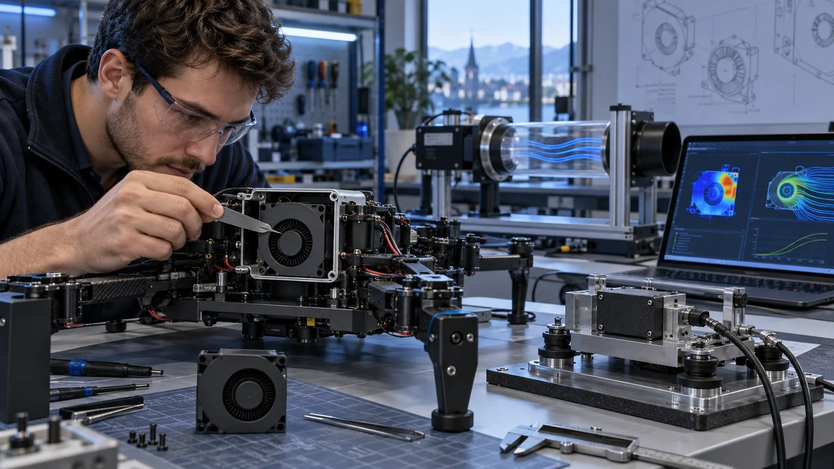
Article brief
A sample is not validated because it spins on a bench. It is validated when the measured fan, installation, control method and operating point agree with the requirement that will be used in production. This checklist is written for purchasing engineers, thermal engineers, mechanical designers and quality engineers who need to make a clear decision after receiving cooling fan samples.
The article separates fan-level evidence from equipment-level evidence. That distinction prevents a common mistake: accepting a fan because it matches a catalogue outline while the installed assembly has a blocked inlet, a different terminal voltage, an unexpected filter pressure drop, a noisy guard or a system controller that does not provide the intended command.
1. Define what the sample must prove
Before opening the carton, write a validation brief. Include the sample part number or drawing revision, frame size and thickness, nominal voltage, allowable voltage range, AC frequency or DC control interface, target airflow and static pressure at that airflow, acoustic target, ambient temperature range, installation orientation, service-life assumption and quantity to be evaluated.
Separate contractual requirements from engineering targets. A target may be refined after a prototype test; a requirement needs an approved change record. This distinction matters when procurement compares a replacement sample with an older fan.
Do not use same size as the acceptance criterion. Two fans with the same outline dimensions can have different impellers, motor operating points, pressure capability, noise characteristics and electrical behavior. The useful comparison is the operating point: airflow at the pressure created by the actual inlet, outlet, filter, grille, heat sink, duct and cable arrangement.
2. Verify identity and traceability
The first physical check is identity control, not performance. Compare the label, connector, wire order, drawing, sample request and packing list. Record the date received, sample quantity, visible serial or lot information, bearing or sleeve configuration when specified, and every engineering change level shown on the documents.
Photograph the label, connector, airflow arrow, rotation arrow, mounting holes and visible damage before testing. Measure the frame dimensions, mounting-hole pitch, corner radius, cable exit position and maximum interference envelope. Record whether a guard, filter, adapter or gasket came with the fan or was added by the equipment team.
Keep one sample untouched. Do not modify every unit at once. The untouched unit provides a comparison if a connector is re-terminated, mounting torque changes, a guard is removed or a fixture is revised. Label each sample so variation in the fan can be separated from variation in the test setup.
3. Confirm electrical input and control
Measure voltage at the fan terminals while it is running, not only at the power supply. Long cables, connectors, protection devices and switching components can create a voltage difference that changes speed and airflow. Record the supply model, cable length, wire gauge, connector and measurement point.
For an AC fan, confirm actual nominal voltage, frequency, phase arrangement and switching sequence. Test the lowest and highest expected line conditions when they are part of the requirement. A fan that starts at nominal voltage may behave differently during a cold start, generator transfer, contactor drop-out or restart after an interruption.
For a DC fan, record applied voltage, current, PWM frequency and duty-cycle definition. Do not assume that a 20 percent command means the same speed on every control input. Confirm whether the signal is open collector, push-pull or another interface, and whether the fan needs a defined pull-up or pull-down.
Check tachometer or frequency-output behavior at stopped, low-speed, nominal-speed and maximum-command conditions. Confirm pulse count from the actual sample documentation rather than from a controller display. If the design uses locked-rotor, alarm or fault output, test response and recovery as separate items.
4. Check mechanical fit before airflow
Install the sample with the planned screws, grommets, gasket, guard and bracket. Use the production mounting torque or document a temporary torque. Check that the frame is not distorted by the screw pattern. A distorted frame can change blade clearance, create rubbing noise or alter the air path.
Inspect inlet and outlet free area, not only nominal grille size. Look for cable loops, stamped louvers, protective mesh, filter frames, heat sinks and nearby walls. A fan can show acceptable free-air flow and still fail in the final housing because the inlet contraction or outlet expansion is too abrupt.
With power removed and the procedure safe, inspect for rubbing, loose parts, foreign material and abnormal axial or radial play. Then run the fan at each required orientation. Record orientation-dependent noise or starting behavior. If a fan is used near a hot panel, check clearances after thermal expansion rather than only at room temperature.
5. Establish the pressure-flow operating point
The core performance check is a pressure-flow measurement. Define the airflow measurement device, pressure tap location, straight lengths, leakage controls, stabilization time, air-density correction and measurement uncertainty. The instrument range must cover both the expected operating point and a higher-resistance condition without forcing the sensor to work at the edge of its accuracy.
At minimum, measure a low-resistance point, the expected system point and a higher-resistance point. If the equipment uses a filter or heat exchanger, include the clean condition and the defined loaded condition. If pressure drop changes with temperature or flow direction, record that condition.
Use the fan curve or supplier test record as a comparison reference, not as a substitute for the installed test. State whether pressure is static pressure, total pressure or another defined quantity. Do not combine values from different methods without understanding the reference planes.
If measured airflow is lower than expected, check leakage, density, sensor zero, fan speed, rotation direction, inlet disturbance and fixture blockage before rejecting the sample. A failed result should start a controlled investigation, not an immediate part-number change.
### Sample validation record
| Check | Evidence to record | Acceptance decision |
|---|---|---|
| Identity | Label, drawing revision, connector and sample ID | Matches approved request |
| Electrical input | Terminal voltage, current, frequency or PWM command | Inside defined test window |
| System operating point | Airflow, pressure, temperature and density basis | Meets requirement at real restriction |
| Speed feedback | RPM or pulse frequency at each command | Stable and usable |
| Noise | Meter position, background, dB(A) and tonal notes | Meets acoustic target |
| Thermal behavior | Hotspot temperature and time to steady state | Protected component stays within requirement |
| Start and restart | Cold start, warm restart, interruption and recovery | Meets defined sequence |
| Mechanical fit | Envelope, torque, gasket, guard and cable route | No interference or induced rubbing |
| Environment | Temperature, humidity, dust and condensation sequence | No unacceptable behavior |
| Documentation | Curve, drawing, wiring, revision and deviations | Complete for design review |
6. Validate noise and vibration in the assembly
Start with a repeatable background measurement. Record the room, microphone distance, weighting, bandwidth or analyser settings, mounting condition and operating point. One dB(A) value may hide a tonal problem. Listen for blade-pass tone, motor commutation, bearing noise, rattling guard, cable contact, airflow separation and enclosure resonance.
Measure normal operation, maximum command, restart, filter condition and speed-control transitions. If the product uses PWM or stepped speed, measure the transition, not only steady states. A fan may be acceptable at full command and objectionable at an intermediate speed because a structural mode is excited.
For vibration, record fixture, sensor location, bandwidth and direction. Check the fan alone and installed in the production panel. If vibration changes after tightening a screw, investigate frame distortion, soft mounts, panel resonance and blade balance. Do not hide a configuration-dependent result by averaging it away.
The approval record must state whether the limit applies to the fan, panel or complete assembly. A fan manufacturer can help with fan-side investigation, but the equipment owner must control panel resonance, mounting structure and system acoustics.
7. Test thermal behavior and protection boundaries
Measure the components that the fan is intended to cool and the locations that can limit the fan: motor area, bearing region, nearby electronics, filter frame and power switching parts. Record inlet-air temperature and local temperature near the fan because they may not be the same.
Test the worst credible combination rather than an average room condition. Examples include high ambient temperature, loaded filter, reduced voltage, restricted outlet, neighbouring heat sources and a rapidly changing control command. Limits belong to the equipment specification and component data sheets. If no limit has been defined, the sample is not ready for final approval; create the missing limit as an engineering action.
Check protective behavior without claiming that a fan protects the whole machine. A fan alarm, locked-rotor output or controller response is only one part of the equipment safety design. Document what the sample did and what the system controller did.
MEGA Tech develops and manufactures custom cooling fans and supports fan selection, air-path review, sample validation and volume production. Cabinet safety, emergency ventilation, coils, liquid loops and controllers remain with the equipment owner or system integrator.
8. Verify start, stop and abnormal sequences
A steady-state run does not prove reliable startup. Define cold start, warm restart, repeated cycling, power interruption, control-signal loss, undervoltage and recovery. For AC products, include the actual switching device and frequency condition. For DC products, include the power converter, cable drop and controller startup order.
Record time to stable rotation, current or power during startup when the instrument supports it, and the result of each restart. If the fan does not start, separate a fan problem from a system sequence problem. The controller may release the enable signal too late, a protection device may open, or available terminal voltage may be below the fan requirement.
Do not create an acceptance number from one lucky restart. Use a defined cycle count and environmental condition approved by the equipment team. If a failure occurs, preserve the sample and fixture state, then capture voltage, command, speed, temperature and alarm evidence before resetting the system.
9. Run environmental and contamination checks
An environmental plan should reflect where the equipment will operate. State the temperature ramp, humidity exposure, dust or filter condition, condensation sequence, storage period, powered and unpowered portions, and recovery inspection. A generic outdoor label is not a test method.
Condensation deserves a separate check. A cold surface can fall below the local dew point while surrounding air is humid. Determine where water can collect, how it drains, whether the fan can start while surfaces are wet, and whether airflow carries droplets toward electrical parts. The fan does not remove the need for enclosure drainage, sealing and system-level environmental design.
For dust, define source, loading method, filter state and inspection interval. Measure pressure drop across the filter before and after loading. A fan can continue to rotate while the equipment silently loses airflow. The useful pass/fail evidence is the protected-component temperature and measured operating point, not only the fact that the impeller turns.
10. Decide whether the sample is production-ready
Classify each item as pass, pass with approved deviation, fail with corrective action or not tested. Not tested must not become pass by omission. Link each result to sample ID, fixture revision, instrument ID, controller revision and test date.
Review deviations with engineering and purchasing. A connector substitution, different cable length, changed guard, revised gasket, different bearing option or unrecorded drawing change can invalidate an otherwise good comparison. The approved sample should be the configuration that production will actually receive, not a special unit that cannot be traced.
For a custom fan, the next step may be a revised sample rather than immediate production. A clear report states what changed, what must be retested and which requirements are closed. This is safer than repeating the full test without identifying the failed variable.
Planned dynamic particle SVG
Filename proposal: uploads/blog/industrial-electronics/cooling-fan-sample-validation-flow.svg
Figure brief: create three connected panels in the MEGA Tech engineering style. Panel one shows sample identification and wiring. Panel two shows blue air particles moving through a filter, fan and equipment load while pressure and temperature checkpoints appear. Panel three shows the review gate branching to pass, approved deviation or retest.
Use blue particles for airflow, amber markers for measurements, red particles only for a failed or unresolved path, and grey blocks for missing evidence. Animate particles with inline CSS keyframes inside the SVG. Do not add a reduced-motion guard. Include the caption exactly: “Illustrative only, not product data.” Add the small disclaimer: “Schematic model / illustrative only — not data for any specific product.”
The figure must not show invented CFM, pressure, temperature, life, certification or pass-rate values. It is a process illustration, not a performance chart.

11. MEGA Tech sample-review workflow
MEGA Tech develops and manufactures custom cooling fans. The workflow can include fan selection, air-path review, sample validation and transition to volume production. Selection should be based on airflow and static pressure at the required operating point, not on a part number or outline dimension alone.
For a useful review, send fan envelope and mounting details, airflow and static-pressure target at that airflow, voltage and tolerance, AC frequency or DC control interface, connector and cable requirements, speed or tach feedback, noise target, quantity, temperature and humidity basis, dust or filter condition, orientation and life assumption. If a P-Q curve or test record exists, include its test method and reference plane.
Start with the MEGA Tech products, use the fan selection tool, and review the AC startup and voltage-sag validation guide. For a replacement project, the same-size fan operating-point case explains why dimensional matching alone is insufficient.
To request a sample recommendation, send fan size, voltage, airflow and static-pressure target, quantity, control, noise target and environmental constraints to WhatsApp or inquiry@cnmegatech.com.
12. Engineer FAQ
### Do I need a full P-Q curve for sample approval?
Not always, but you need enough pressure-flow evidence to demonstrate the real operating point and its uncertainty. A single free-air CFM value cannot show whether the fan will overcome a filter, grille, heat sink or duct. If the system point is unknown, define and measure the restriction before approval.
### Can I approve a sample from the catalogue?
Use catalogue data as a reference and check its test method, air density, speed, pressure definition and configuration. The installed test still needs to prove fit, electrical behavior, noise and thermal performance in the equipment.
### How many samples are enough?
The number depends on risk, variation, validation plan and production controls. Do not use a universal count. Define the quantity with engineering and quality, then record results per sample so abnormal variation is visible.
### Should noise be tested before airflow?
Both matter, but noise without a defined operating point is difficult to interpret. Measure acoustic behavior at the airflow and pressure conditions the equipment will use, then investigate tonal or vibration changes across the control range.
### What should purchasing request before an order?
Request the approved configuration, drawing and wiring information, the conditions behind performance data, environmental requirements and open deviations. Ask engineering to approve the actual sample, not only a similar model name.
Questions for a Design Review
1. What airflow and static pressure are required at the same operating point?
2. Which pressure definition and air-density basis are used?
3. Are voltage, frequency, PWM, FG or RD and startup sequence defined at the fan terminals?
4. Does the fixture reproduce the production grille, filter, gasket, guard, cable route and nearby walls?
5. Which component temperature is the limiting requirement, and how is it measured?
6. What is the cold-start, warm-restart and power-interruption sequence?
7. Where can condensation form, and how does water drain away from electrical parts?
8. What filter loading or dust condition represents service, and what pressure-drop limit triggers maintenance?
9. Are noise and vibration limits tied to a measurement position and installation?
10. Which results are pass, approved deviation, fail or not yet tested?
11. Is the sample configuration traceable to the intended production configuration?
12. Which remaining responsibilities belong to the equipment owner or integrator?
External references to verify before publication
- AMCA standards and publications
- IEC 60034-1 rotating electrical machines
- These links should be checked for current availability before publication. No third-party performance value is presented as MEGA Tech data in this draft.
