The fan that cools a charger dies from dirt and heat, not from reaching its rated hours
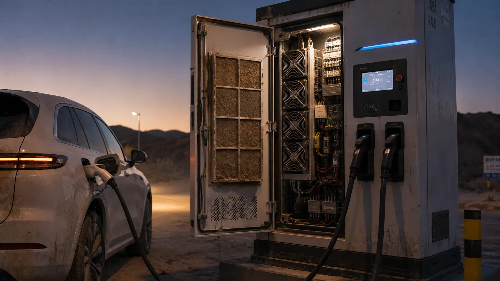
A data-center fan lives in a filtered, climate-controlled room and barely feels its first year. The fan inside an outdoor DC fast charger lives in truck-road dust, summer cabinet heat and repeated stop-start shocks. When it fails in year two, it was almost never 'worn out by age' — it was killed by dust blocking the filter and heat baking the bearing lubrication, while the controller never noticed because speed stayed the same.
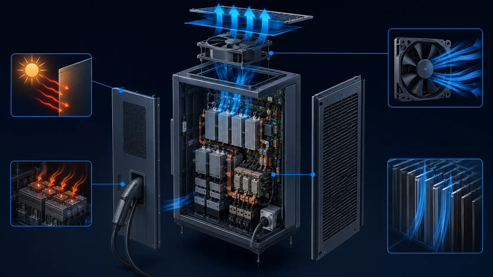
The physics stack up fast. In an illustrative 350 kW cabinet, 95–97% conversion efficiency corresponds to about 18.4–10.8 kW of conversion loss using loss = output ÷ efficiency − output, before auxiliary loads and solar gain are added. The actual efficiency curve must come from the charger design. Solar exposure can also raise the fan inlet and component temperatures substantially above shade ambient, so the thermal model needs enclosure finish, orientation, irradiance and airflow measurements rather than a universal cabinet-temperature number.
This is the failure that quietly derates chargers: the fan turns at the same RPM it always did, so the controller thinks cooling is fine, but the airflow crossing the cabinet has dropped as the filter or heat exchanger loads. Power-module and cable temperatures climb, the charger throttles current to protect itself, and at the roadside the customer just sees slower charging. The service cost is site-specific; calculate it from access, travel, downtime and replacement procedure rather than using a universal truck-roll number.
This article is about why that fan's useful life is set at selection time — by the static-pressure headroom you size in and the bearing you choose, not by a lifecycle figure on a datasheet — and about how a fan specified around a specific outdoor environment survives years that a one-size-fits-all unit never will.
Dust moves the working point, not the speed sensor
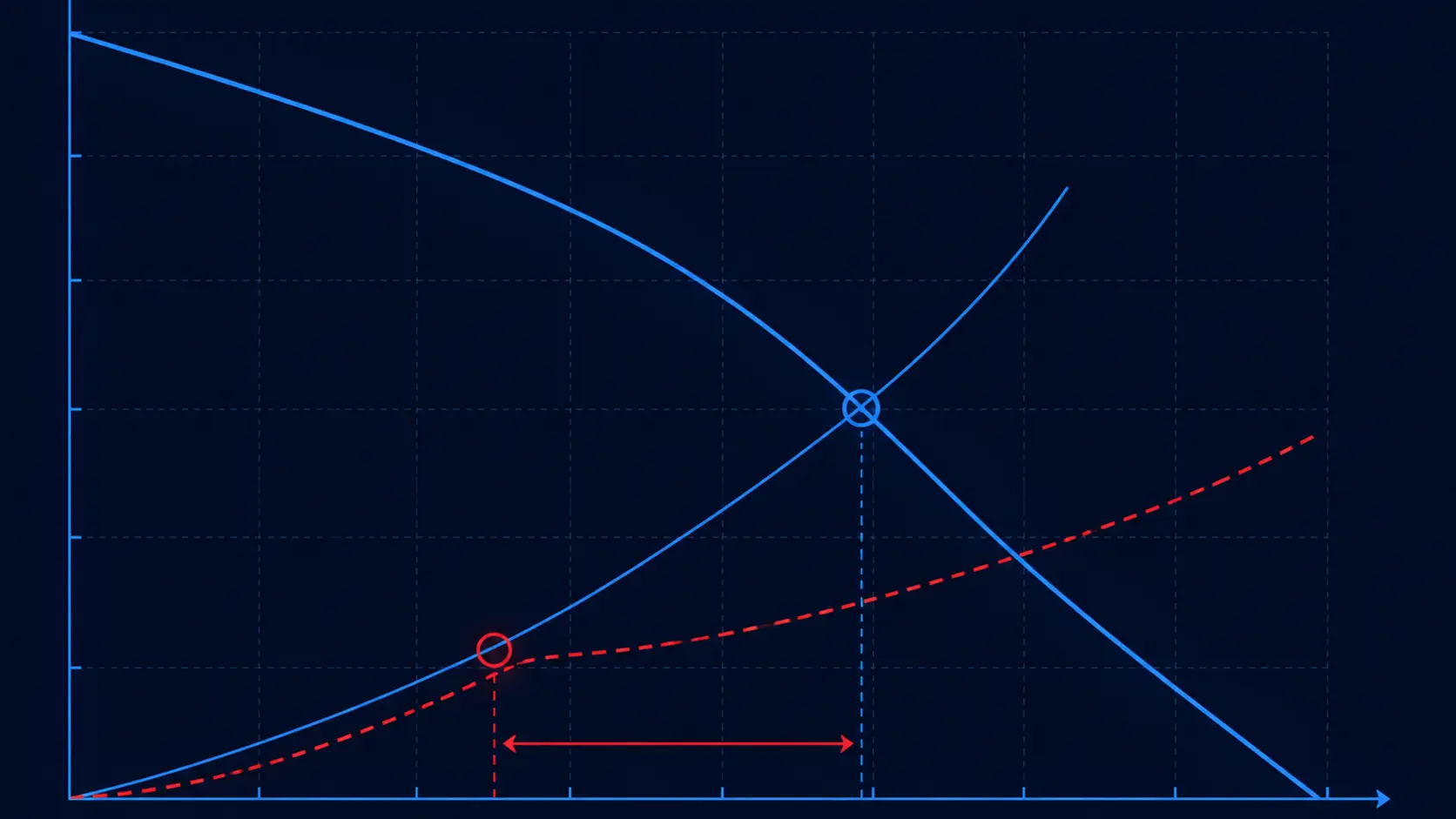
A fan and its duct work together as two curves. The fan has its own pressure–airflow (P–Q) curve: push against more resistance and it delivers less airflow. The cabinet adds its own curve — the system resistance — which rises as the filter loads with dust. The fan settles where the two curves cross, and that crossing point is your real airflow.
When the filter and heat-exchanger fins coat with dust, the system curve steepens and the operating point slides up-pressure and down-airflow. The fan's speed barely changes, so a tachometer reports 'healthy', but the part receiving the air is getting a fraction of what the datasheet promised.
The engineering conclusion is simple even when the numbers are not: at equal fan size, a fan with a stiffer static-pressure curve can preserve more useful airflow through a loaded filter and fin stack. The required CFM, pressure and fan count must come from the charger's system curve and heat balance; a generic 120 kW or 300 Pa rule is not transferable between cabinets. Pressure is what pushes air through restrictions; free-air volume alone is a number on a page.
The metric an outdoor charger should be designed around is therefore not free-air CFM at all — it is the airflow that remains once the filter has collected a season of dust.
Heat is the other lifetime thief: measure the inlet temperature
Fan lubrication and bearing life are strongly temperature-dependent, but the life multiplier depends on the bearing, grease, speed, load and test method. A fan chosen for a 40°C rack room cannot automatically be treated as suitable for a hotter sun-loaded charger cabinet; use the fan supplier's life curve at the actual inlet temperature.
What happens inside the bearing is chemistry as well as wear. Sustained high temperature can accelerate grease oxidation, separation and migration, while dust and moisture can contaminate the raceway. Specify a grease and seal strategy for the site's temperature and exposure range, then validate it with the fan assembly rather than copying a generic lubricant temperature range.
Bringing the air temperature down at the fan inlet usually creates life margin, but the amount must be measured or calculated for the chosen bearing and duty cycle. Placement away from the hottest modules, better airflow and reduced high-speed operating time all help; none replaces a real thermal-life validation.
That is why 'how much air' is not the only question: where the fan sits relative to the heated electronics, and what temperature its inlet actually sees, drive lifetime as hard as raw airflow does.
Bearing failure is the headline in every field-return report
When an outdoor charger's fan dies early, the bearing is one of the first subsystems to investigate, alongside contamination, winding insulation, drive electronics, connector integrity and mounting vibration. Grease degradation, dust ingress and moisture exposure can all reduce life, but the root cause should be confirmed from the failed part and the site history rather than assumed.
Bearing selection should state the shaft orientation, temperature, speed, load, contamination level and test condition. Dual ball bearings may offer useful margin for outdoor charger duty, while sleeve bearings can be more sensitive to orientation, temperature and lubrication; the correct choice remains application-specific. Ceramic hybrid bearings can be considered where electrical or service constraints justify their cost, but they should not be presented as a universal requirement.
Compare bearing options using the complete cost model: validated life at the loaded-filter duty, planned replacement access, downtime, spares and field service. A higher-priced fan is worthwhile when its measured reliability and serviceability reduce total ownership cost, not simply because its catalogue L10 number is larger.
Static-pressure headroom is your lifetime budget
Because dust is guaranteed and heat is severe, the useful life of a charger fan is fixed not by its datasheet life figure but by how much static-pressure headroom you gave it at selection. A fan with a shallow P–Q curve may work beautifully clean and then collapse the moment the filter loads; a stiffer, higher-headroom fan keeps useful airflow far longer as dirt builds up.
This is where choosing between fan sizes matters. A larger, lower-speed axial fan (for example a 120×120×38 mm unit in 24 V) can provide more pressure and airflow margin against a loaded filter than a smaller high-speed fan forced to spin near its limit, but the result must be checked on the installed system curve. Lower speed can also reduce bearing duty and acoustic output at a comparable operating point; it is not a substitute for validating temperature, pressure and life at the actual site.
The catalogue span below covers this deliberately — a compact high-static-pressure blower class for a tight local heat source, a mid-size high-static axial for the charger module, and a larger-volume axial for whole-cabinet exhaust — so you can pick the headroom profile that matches where your cabinet's filter will actually sit.
Headroom buys time, not immunity — the maintenance interval still has to exist, and it should be set by measurement rather than habit. Start with a site-specific inspection plan, then tune the interval from filter loading, pressure drop and airflow trend. A differential-pressure indicator across the filter turns the guess into a gauge: when the drop across the media approaches the level that would pull the fan's operating point below the required airflow, the filter gets swapped before derating. Filter service is easier to schedule than an unplanned roadside failure.
Voltage architecture closes the selection loop. Match the fan to the charger's existing control rail where practical; 24 V and 48 V platforms each have legitimate packaging and wiring trade-offs. A dedicated supply adds another component and another failure mode, so the voltage, startup current, PWM interface and fault behaviour should be checked as part of the complete cabinet design.
| Model | Size / 24V | Free-air CFM | Static pressure | Noise |
|---|---|---|---|---|
| MG12038HV24X | 120×120×38 mm | ~210 CFM | ~29 mmH2O | ~65 dBA |
| MG8038HV24X | 80×80×38 mm | ~129 CFM | ~127 mmH2O | ~79 dBA |
A speed signal is only useful if it measures the right thing
Most chargers watch fan speed and raise an alarm only when the fan stops or stalls. Against dust-driven airflow loss that is almost useless — a filter can be one-third choked and the fan spins at its normal RPM the whole time. The signal someone actually wants is airflow or, failing that, a temperature rise across the heat source.
In practice the best use of fan intelligence is twofold: PWM that lets the controller run the fan fast when the cabinet is hot and slower when it is not, reducing unnecessary high-speed duty, and a tacho/RD or alarm output so a stalled or dead fan is reported instead of the charger cooking silently to derate. Rotation detection is useful, but speed alone still does not prove airflow through a loaded filter.
One more electrical detail outdoor designs cannot skip: the fan's own PWM switching must not pollute the cabinet. The charger supplier should evaluate fan-driver emissions and immunity within the applicable EVSE and cabinet EMC plan, including the relevant IEC 61851 family requirements and any regional standards. A fan that is electrically noisy can become a compliance problem wearing a cooling label.
When you specify a fan, state explicitly which outputs you need and whether the fan must hold a guaranteed airflow (and therefore a true L10 life) at the loaded-filter pressure — not merely spin at a set RPM.
- Demand PWM speed control so the fan idles on cool nights and the bearing sees fewer hours at high load.
- Use a tacho/FG or alarm output to catch a stalled fan fast — but never trust speed alone to mean airflow.
- Require EMC-clean PWM switching — the fan shares a cabinet with metering and communication electronics.
- Specify the guaranteed airflow at the dirty-filter pressure drop, which is the number your cooling design actually consumes.
Different outdoor sites need different fans — that is the case for customization
A standard catalogue fan is a single answer aimed at every cabinet at once, and every cabinet is different. A coastal station needs a corrosion and moisture strategy; a desert station needs a filter and ingress strategy; a cold-climate installation needs a startup-temperature and grease review. One fixed bearing choice, one fixed life figure and one fixed speed can be a poor compromise. The correct protection level should follow the enclosure, service method and site exposure.
Do not treat IP rating as a guarantee that a fan will survive every outdoor site. A sealed or potted design can reduce ingress paths, but it also changes heat rejection, repairability and production inspection. Validate the complete fan assembly under the actual temperature, dust, humidity, salt and vibration conditions, and use representative samples before making a field-life claim.
Beyond ingress protection, specifying around the site changes the whole part: bearing and grease for temperature and vibration; a sealed or filtered inlet strategy for sand; pressure headroom for a persistently dust-loaded filter; and a speed and power point that fits the cabinet's measured system curve. Corrosion resistance has its own checklist — materials, fasteners, coatings and connectors — validated with the selected ISO 9227 salt-spray method and the customer's real exposure profile.
- Bearing type chosen for the site: dual ball-bearing floor for salt, heat or vibration; potted and sealed where dust and water ingress dominate.
- Target life set as an engineered L10 at the real loaded-filter airflow and real inlet temperature, not a datasheet default.
- Working point and speed matched to the cabinet's measured system-resistance curve, so the fan is never over- or under-provisioned.
- Build details to order: wire length, terminal and IP-rated connector, mounting holes, and logo or unbranded ODM finish.
- The supplier works from your enclosure's resistance and thermal data and returns a fan spec — not the other way around.
Build the charger fan around the site
The right outdoor fan is developed from the charger enclosure and deployment environment, not selected from a generic indoor catalogue.
MEGA Tech can work with charger and power-electronics teams to convert the site requirement into a practical fan specification. We review the cabinet airflow path, loaded-filter pressure, fan inlet temperature, dust or salt exposure, required IP level, voltage, noise limit, control signals, connector and expected service life.
Where a standard model is close but not enough, we can adjust the fan around the application: higher pressure margin, different speed or voltage, dual-ball bearing and high-temperature grease, sealed or protected construction, PWM and FG/RD feedback, cable and connector configuration, mounting details and other integration requirements. The goal is not to oversize every fan; it is to keep the required airflow at the real working point for the actual site.
For a new charger platform or a smaller development program, the process can start with a limited sample build. We test the production-representative fan in the cabinet or a representative airflow fixture, review temperature, airflow, pressure, noise and control response, then refine the approved design before volume production. This gives the customer a dependable alternative to high-priced international brands without forcing a premature large order.
- Define the site environment and loaded-filter working point.
- Customize bearing, protection, control, wiring and mechanical details around the charger.
- Validate a production-representative sample before release.
- Scale the approved specification into reliable, cost-conscious production.
Engineer FAQ: EV Charger Fan Life Under Dust and Heat
An outdoor charger fan is a monitored airflow subsystem whose life depends on the loaded cabinet condition and site environment.
Q: Why can a charger fan keep its RPM while useful airflow falls? A: Filter or heat-exchanger loading increases system resistance, moving the operating point to lower airflow while the motor still turns at the commanded speed. Pair speed feedback with pressure, airflow or thermal trend data.
Q: Is a higher IP-rated fan automatically better outdoors? A: No. IP applies to a defined enclosure test condition and does not by itself qualify the complete charger for dust, salt, condensation, solar heating or service exposure. Validate the fan, filter, connector and cabinet as one environmental system.
Q: Should every outdoor charger use dual-ball bearings? A: No universal bearing floor applies. Compare the exact bearing and grease against temperature, shaft orientation, contamination, vibration, speed, duty cycle and documented life data for the selected fan.
Q: How should the dirty-filter condition be specified? A: State the filter pressure drop or system resistance at the required airflow, including the maintenance limit. Then verify the fan P-Q curve, inlet temperature, current and component temperature at that loaded condition.
Q: What should a charger fan sample prove before production? A: Test the representative cabinet with the real filter, heat exchanger, control rail and fault logic across clean and loaded conditions, hot ambient and relevant solar exposure. Record airflow, pressure, temperature, noise, RPM, PWM response, EMC behavior and service access.
- Tie every numerical answer to voltage, speed, temperature, mounting and test condition.
- Separate catalogue maximums, engineering estimates and measured application results.
- Use the FAQ to define the next measurement or sample-validation step.
The checklist — size the headroom, know the heat, customize for the site
Working through a charger fan so it survives the roadside instead of a clean lab:
- Know the worst-case air temperature at the fan inlet, including solar loading, and use the supplier's life curve at that temperature and duty cycle.
- Size for airflow at a loaded filter, not free-air — prioritize static pressure over volume in high-power cabinets, and ask for headroom to keep cooling through the dust season.
- Select bearing type and grease from the site's temperature, orientation, contamination and service requirements; compare ceramic hybrids only where their verified benefit justifies the cost.
- Consider a larger, lower-speed fan where space allows; verify its loaded-rack airflow, noise and bearing life rather than assuming size alone solves the problem.
- Fit PWM speed control, a tacho/FG or alarm output, and verify the fan's EMC behaviour alongside the charger's own metering and communications.
- Specify exactly the outputs, guaranteed airflow and target L10 life you need, and pull in a supplier that custom-builds bearing, ingress protection, speed and working point for the site — not just a stock pull.