Liquid Cooling Does Not Remove the Fan From the System
A liquid-cooled battery pack moves its heat with water-glycol, but the loop must give that heat to somewhere, and in a passenger car that somewhere is almost always ambient air pushed through a radiator by a fan.
The confusion shows up in fan inquiries. A team specifies a liquid cold plate, a pump and a chiller, then treats the radiator fan as a commodity chosen by diameter and voltage. The pack then underperforms in exactly the conditions the liquid loop was supposed to solve: summer fast charging, repeated hill climbs, and the ten minutes after a hard pull into a charging stall at 35 degrees Celsius ambient. The liquid loop moved the heat to the radiator; the fan decides whether it leaves the vehicle.
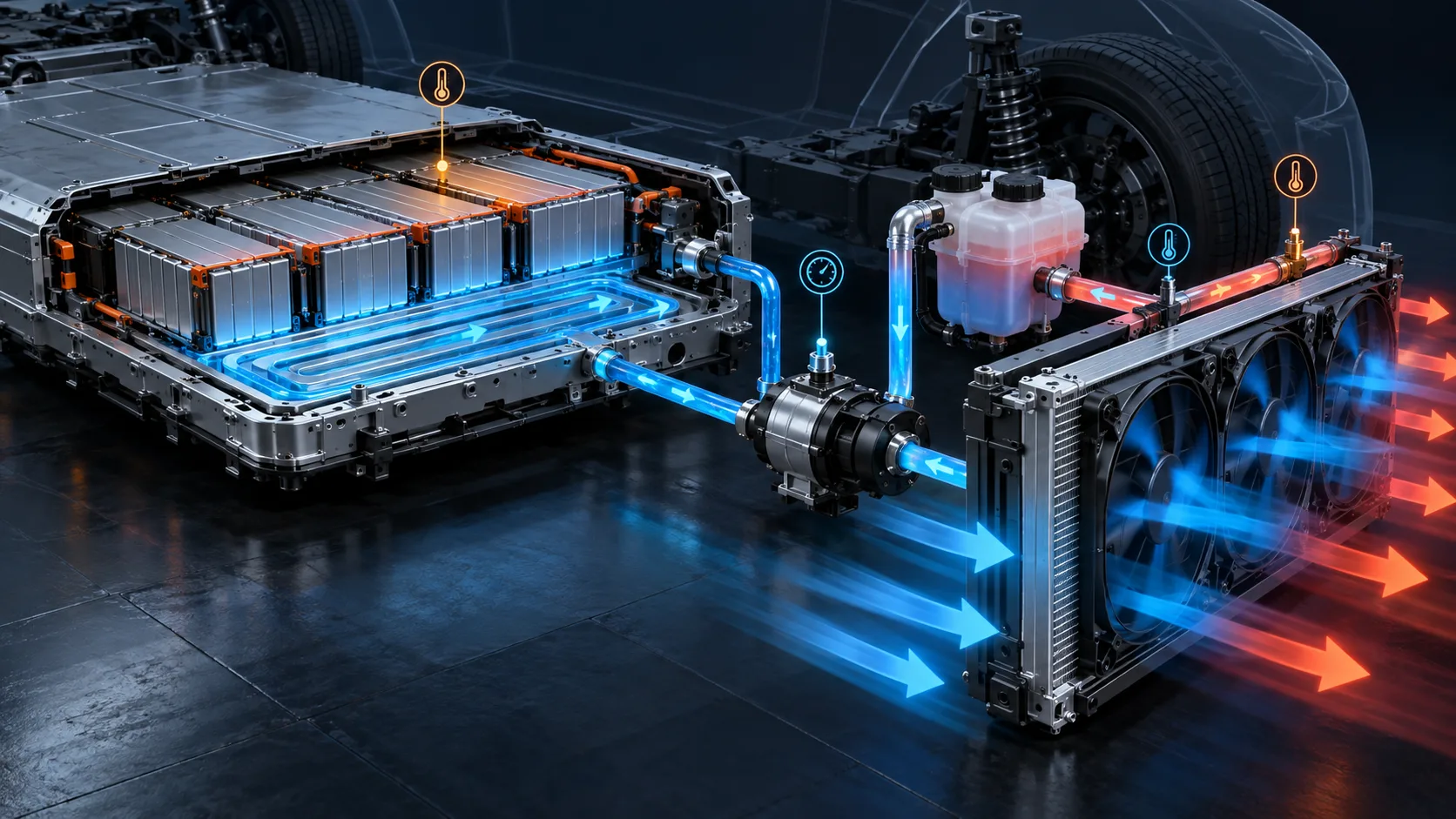
The figure below shows the two loops and the wall between them. Blue is the sealed coolant circuit: pump, cold plates under the cells, hoses, radiator tubes. Orange and green are the open air circuit: ambient air through the grille, through the radiator core, out past the fan. Heat crosses the wall; the two fluids never mix. The fan sees air and radiator fin, never cells.

Start From the Heat the Loop Must Reject
Every fan number downstream depends on one input the fan vendor rarely gets: how many kilowatts the loop must reject, in which driving or charging condition.
Today's production battery cooling systems reject roughly 1 to 5 kilowatts in normal driving, according to NREL's extreme fast charge analysis, and the same analysis puts the target near 15 to 25 kilowatts when a pack must accept extreme fast charge without throttling. That spread is not a rounding error. It is the difference between a 300-millimetre fan module loafing at part duty and a two-fan module running near its limit.
The cell-level reasons are well documented. A serpentine liquid-cooled pack study published in Scientific Reports in 2026 held maximum cell temperature to 42.5 degrees Celsius at a 6C discharge, while recording that capacity retention falls from nearly 100 percent to about 70 percent as the rate climbs from 0.5C to 6C when thermal control is inadequate. Heat that stays in the cells is measured directly in cycle life.
Pack-level evidence is just as sharp. An Idaho National Laboratory study of 50-kilowatt direct current fast charging, published in the Journal of Power Sources, found that complete packs faded significantly faster than individual cells run through the same charge protocols. Pack-level aging cannot be extrapolated from cell tests, and the thermal system is one of the reasons. Where the waste heat of a 7.5 kW charger goes, and how to keep it out of the electronics works the same heat balance from the charger side.
Where the Fan Sits in a Liquid-Cooled Vehicle
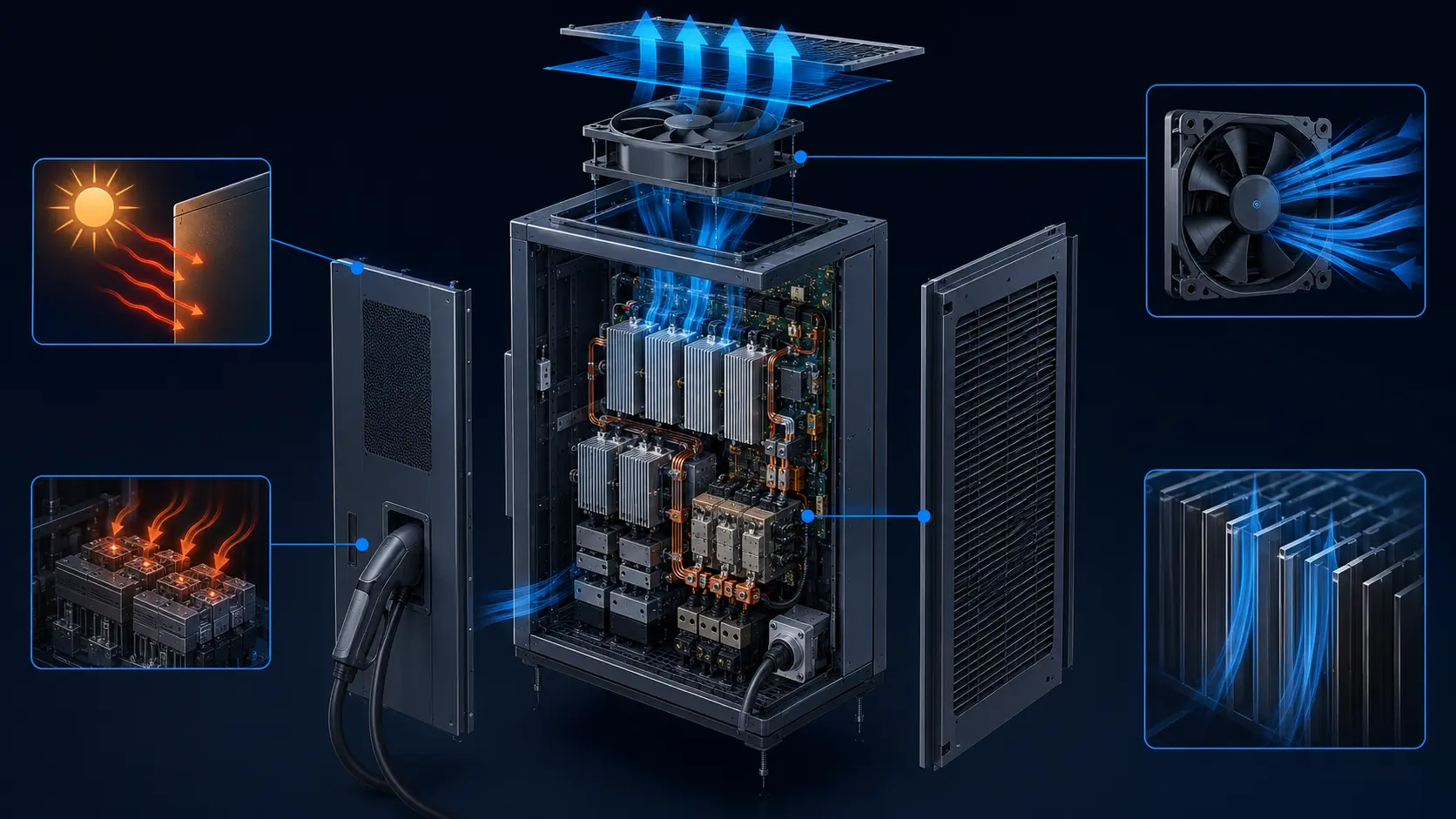
The fan lives on the air side of the radiator, downstream of every liquid decision, and its whole job is to keep the coolant temperature low enough that the cold plates can hold the cell limits.
Follow the heat. Cells conduct into cold plates; plates conduct into 50/50 water-glycol moving at roughly 6 to 12 litres per minute; the pump keeps that flow against a cold-plate and loop pressure drop of tens of kilopascals on the liquid side. The coolant arrives at the radiator several degrees warmer than it left the pack, and the radiator hands the heat to air flowing through its fin core. The fan, usually a 300-millimetre-class axial module behind the core, supplies that air.
Two consequences follow. First, the fan never touches the pack, so every battery-related requirement - isolation, sealing against the cell environment, thermal runaway containment - belongs to the liquid loop, not to the fan. Second, the fan's real specification is written by the heat exchanger: a radiator that is 20 percent undersized cannot be rescued by fan choice alone, and a radiator that is well sized still fails if the fan stalls in the dense air path behind a condenser and a grille.
This division of labor is the same one that governs liquid-cooled systems in other industries. The hybrid liquid-air architecture used in AI data centers separates a sealed pump loop from an open air loop at a liquid-to-air heat exchanger, and the fan selection logic there, which our data center hybrid cooling article works through in detail, transfers almost unchanged: the fan is selected on air-side airflow and pressure, against an air-inlet temperature it cannot control.
Size the Airflow From Heat and Permitted Air Rise
The first fan number comes from a heat balance on the air side: kilowatts to reject, divided by what one kilogram of air can carry at the temperature rise you allow.
Air is a poor coolant, which is why the flow numbers look large. At 35 degrees Celsius ambient, air at 1.15 kilograms per cubic metre carries about 1,006 joules per kilogram-kelvin. Allowing a 15 kelvin rise across the core, rejecting 8 kilowatts needs about 0.46 cubic metres per second, near 1,000 CFM. The 15-kilowatt fast-charge case needs near 1,900 CFM at the same rise. Halve the permitted rise and the airflow doubles; that trade is set by radiator face area and by how much RAM air the vehicle can credit at speed.
The permitted rise is not free. The coolant must leave the radiator colder than the cells' control band requires, the ambient is whatever the market sells into, and the air heats up as it crosses the condenser stacked in front of the radiator. A fan module selected against 40 degrees Celsius incoming air will not deliver its catalogue airflow at 55 degrees Celsius behind a parked condenser baking in the sun. State the worst air-inlet temperature next to the kilowatts, or the number is not selectable.
Find the Operating Point on the Air Side
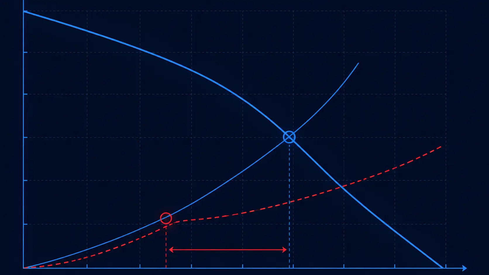
The second fan number is pressure. The fan curve and the installed air path cross at one operating point, and that point - not the catalogue peak - is what cools the car.
The installed path stacks up: front grille and its losses, the condenser if stacked, the radiator core itself, the shroud, and any recirculation path around the module. Cores alone commonly cost 150 to 400 pascals at useful face velocities, and the surrounding hardware adds more. Johnson Electric's automotive fan module platforms, published with air-side ratings, show what the module class delivers: their battery cooling fan modules span 30 to 200 watts input driving 31 to 110 litres per second against pressures up to 600 pascals, with brushless motors rated for 300,000 hours. The same family page lists 12-volt modules from 150 to 1,500 watts input at 42 to 54 percent airpower efficiency - a reminder that module input wattage is not delivered airflow.
Read the intersection honestly. A module that peaks at 1,900 CFM may deliver 1,300 against an installed 300-pascal path. If the heat balance asked for 1,900, the loop runs hot exactly when the vehicle is parked and charging, when there is no RAM air to help. The same operating-point discipline applies to any air-side selection; our liquid-to-air heat exchanger selection article for BESS walks the fan-curve-versus-system-curve intersection with numbers.
Pusher or Puller: Installation Changes the Delivered Flow
The same fan module delivers different airflow depending on which side of the core it sits, what the shroud seals, and how much hot air it is allowed to breathe twice.
A pusher behind the grille works in cooler air and is easier to package, but it sees the condenser's wake and can distribute flow unevenly across the core. A puller behind the core smooths the flow across the whole face and typically measures better at low vehicle speed, but it sits in the hottest air and needs its motor specified for it. Either way, the shroud is not decoration: a module without a shroud leaks flow around the blade tips, and the loss grows exactly where static pressure is highest.
Recirculation is the quiet failure. If hot exhaust is allowed to loop back to the fan inlet - through body gaps, a missing seal, or a shroud opening - the fan keeps spinning at its commanded duty while breathing 50-degree air instead of 35-degree air. The coolant temperature climbs and the controller responds with more duty, more current, more noise. The fix is sealing and a 60-millimetre-class standoff between blade and shroud lip, checked on the bench, not assumed. Installation effects of this kind are documented across industries; the delivery penalty of a crowded inlet applies to any axial fan, in a cabinet or behind a bumper.
The Vehicle Environment Sets the Fan Specification
Automotive qualification is where generic industrial fans stop being an option, and the specification is written in temperatures, ingress ratings, vibration spectra and electromagnetic limits.
Temperature comes first. Underhood and front-module fans are commonly specified from minus 40 to plus 105 degrees Celsius operating, with short excursions beyond, and module families such as Johnson Electric's are rated to 120 degrees Celsius. Voltage rides the vehicle bus: 9 to 16 volts on a 12-volt system, with load dump and cold crank on top. Electromagnetic emissions follow CISPR 25, because the fan shares the vehicle with radios and antennas.
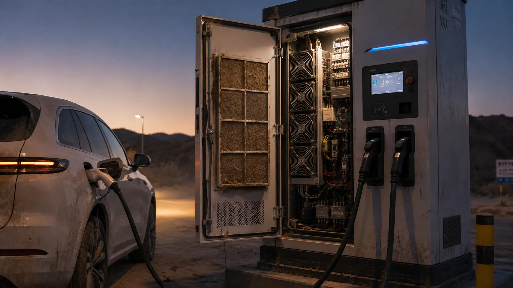
Ingress and vibration remove the remaining shortcuts. Front modules see washer spray, standing water and high-pressure wash-down, which is where IP67 to IP69K ratings on the motor and connector earn their place. Vibration follows ISO 16750-3, with random spectra from roughly 10 to 2,000 hertz across the life of the vehicle; a bearing or mount that survives a bench shaker table may still crack a solder joint in the resonance that a certain road speed excites. Dust and static pressure in exactly this direction, on charge-station hardware, are worked through in our EV charger cooling article.
Control the Fan From Coolant and Charge State
A battery-loop fan should run when the coolant-to-air temperature difference pays for it, and the control table should say so condition by condition.
PWM control on a 12-volt brushless module lets the thermal controller trade acoustic signature against cooling authority continuously. The useful reference is coolant temperature at the radiator inlet, plus the pack's charge state: fast charging in a hot stall commands high duty with the vehicle parked, when fan noise is most noticeable to the user sitting inside. Standing losses matter too - a module that draws significant current in standby drains a parked vehicle over weeks.
Write the duty table before selecting, and test each row. The rows below are the usual contract between the thermal controller and the fan module.
| Condition | Heat to reject | Fan duty | Record at acceptance |
|---|---|---|---|
| Highway cruise | 1-5 kW plus RAM air credit | Low to zero duty, RAM air carries much of the flow | Coolant in/out temperatures and cell band at sustained speed |
| DC fast charge, hot ambient | Up to 15-25 kW target for extreme fast charge | High duty, vehicle parked, acoustic limit applies | Cell maximum and spread at end of charge, PWM duty, fan current |
| Park cool-down after charge | Stored heat in the loop | Medium duty, timed | Coolant temperature decay curve to the control band |
| Winter preheat | Heat retained, not rejected | Fan off or minimum duty, heating loop active | Cell inlet temperature and uniformity at drive-away |
A Validation Plan You Can Reuse
Four measured quantities decide whether the air side works; none of them is the fan's catalogue flow.
Measure coolant in and out of the radiator, air in and out of the core, fan PWM command and current, and fan speed if the module reports it. Coolant-side delta times flow rate gives the heat actually rejected; air-side delta times the measured or estimated air mass flow should agree with it. When the two disagree, the missing heat is usually recirculation, an unsealed shroud gap, or a core bypass - all installation facts, not catalogue facts.
Run the matrix that matches the duty table: worst ambient with the vehicle parked at full charge duty, cruise with RAM air credit verified rather than assumed, and the cool-down transient. A tachometer reading within specification does not prove delivered airflow; RPM is an input to the diagnosis, not the verdict. Why normal RPM does not prove cooling airflow sets out the failure pattern in the language of acceptance measurements.
Record the fan's own evidence at each point: current draw against PWM duty flags a tired motor or a blocked path long before the coolant alarm; a bearing that grows noisy at low temperature is caught by a cold-chamber acoustic check, not by a summer road test.
Where MEGA Tech Fits In
MEGA Tech builds the fan module on the air side of your loop - to your operating point, not to a catalogue footnote.
What we do: custom DC and EC axial fans and backward-curved centrifugal fans, selected against your operating condition rather than a part number. For a battery-loop radiator that means we size the impeller, motor and shroud to your air-side pressure drop and heat rejection, at your worst air-inlet temperature, and we put samples on your vehicle or your bench rig for validation in the real installed path.
What we need from you: the heat rejection in kilowatts and the coolant temperature target at the radiator inlet, the installed air-side pressure budget with grille and condenser, the worst ambient and air-inlet temperature, the voltage window and connector definition, the available space and shroud envelope, the acoustic target for parked charging, and the life assumption in years or hours.
Where our boundary sits: we do not supply radiators, coolant pumps, chillers, refrigerant circuits or the vehicle thermal controller, and we do not certify pack safety or crash performance. Those belong to the thermal system supplier and the vehicle integrator. And we will not claim that a fan is equivalent because its outline drawing matches; the operating point decides.
Recommended Fan Starting Points
These catalogue series may be suitable starting points for this application. Final selection depends on the installed airflow, static pressure, voltage, noise target and operating environment.
Request a sample for validation on your equipment.
Engineer FAQ: Fans in EV Battery Liquid-Cooling Systems
Short answers to the questions this selection raises most often.
Q: If the pack is liquid-cooled, can we delete the fan and rely on RAM air?
A: Only if the vehicle never fast-charges parked and never idles in hot traffic with the loop loaded. RAM air is zero when the vehicle stands still, and parked fast charging is precisely the highest heat case. The fan covers the conditions RAM air cannot.
Q: Can we size the fan from the radiator catalogue's rated airflow?
A: No. Catalogue flow is free delivery on the core alone. Your path adds grille, condenser, shroud and recirculation. Select on the intersection of the fan curve with your installed system curve.
Q: Is a bigger fan the fix for a hot loop?
A: Past the operating point, more fan buys little: airflow rises roughly with the cube of speed only in the fan's own curve, while pressure losses rise with the square of flow in the path. If the core is undersized, a better radiator beats a bigger fan.
Q: Do we need PWM, or is a two-speed fan enough?
A: Two speeds cover cruise and a coarse charge mode. PWM earns its cost in fast charging, where the controller must hold cell limits without exceeding a parked acoustic target, and in standby current management.
Q: What shortens fan life in this application?
A: Bearing wear in hot soak, connector corrosion from wash-down below spec, solder fatigue from road vibration, and repeated overload at high duty against a clogged or recirculating air path.
Questions for a Design Review
Bring answered numbers, not intentions.
- 1. How many kilowatts must the loop reject in each row of the duty table, and which row governs the fan selection?
- 2. What is the worst air-inlet temperature, including condenser preheat when parked in sun?
- 3. What air-side pressure drop did the installed path measure, with grille, condenser and shroud, at the required flow?
- 4. Where does the fan curve cross that system curve, and what margin does the module keep at end of life?
- 5. Which ingress, voltage, vibration and EMC requirements does the module certificate cover, and which are tested at vehicle level?
- 6. How is recirculation excluded - by seal, by shroud geometry, and with what measurement?
- 7. Who owns the coolant loop, the controller strategy and the safety concept outside the air side?