The 7.5 kW that never shows up on the datasheet
Example: a 150 kW fast charger operating at 95% electrical efficiency still has to reject 7.5 kW of heat. The actual loss curve depends on the charger design, load, input voltage and temperature, but the thermal question is universal: where does that heat go during a sustained session?
Efficiency numbers read well in marketing, but they hide the engineering reality of power electronics. In this illustrative case, a 150 kW DC fast charger running at 95% electrical efficiency converts 5% of its delivered power into heat: 150 kW × (1 − 0.95) = 7.5 kW. A 350 kW or 480 kW system can generate several times that, but its real loss must come from the vendor's efficiency-versus-load data rather than a single assumed percentage.
That heat load lands on a dense set of power modules packed into a cabinet sitting in direct sun. If it is not moved out, the modules' junction temperatures climb past their limit, the control system cuts current to protect the hardware, and the charger 'delivers' only a fraction of what its nameplate promises.
This is not a thermal footnote. It affects how much of the rated output a driver actually gets and how long a session lasts. The commercial impact is site-specific, so it should be calculated from measured derating curves and the operator's utilization model rather than assumed from nameplate power.
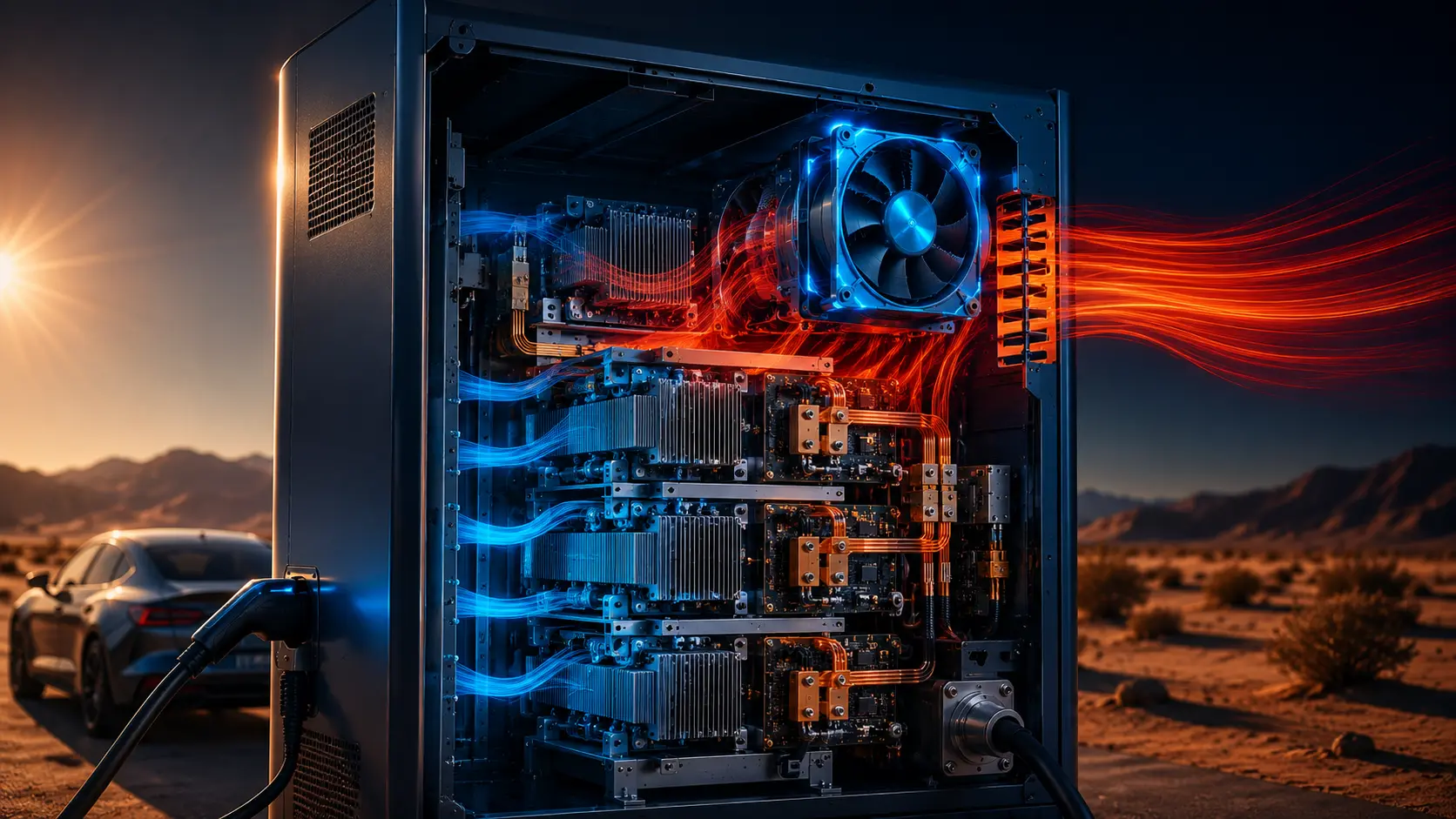
It is also worth being blunt about the exits: that 7.5 kW must leave through the cabinet's designed heat paths — forced air, liquid cooling, conduction to a heat exchanger or a combination of them. Batteries inside the car may pre-condition, but the charger cabinet cannot store heat and deal with it later; heat generated during a sustained session must be rejected at roughly the same rate. The total rejection figure for a higher-power cabinet is architecture-specific, which is why cooling must be treated as a core subsystem rather than an accessory.
You are not selling 95% efficiency, you are selling sustained output
Derating is the mechanism that turns a thermal gap into lost charging speed. When sensors reach a protection setpoint, firmware can step down current to protect power modules, switches, capacitors, busbars and connectors. The relevant setpoints are design- and component-specific; do not transplant an IGBT, capacitor or internal-air temperature from one charger into another. NREL describes thermal management as critical to power electronics performance and reliability, while IEC 61851-23 includes requirements for EV supply equipment with thermal management systems.
The gap between rated and sustained output is therefore a test question, not a universal ambient threshold. Request the vendor's output-versus-ambient and output-versus-time curves, including solar exposure or enclosure heat-load assumptions. If those curves are unavailable, instrument a representative cabinet and record module, coolant or internal-air temperatures while the charger runs at the intended duty cycle.
One more trap: derating curves are not industry-standardised. Two chargers both rated 350 kW can behave very differently at the same ambient because of power-stack layout, firmware, cable limits and airflow. The right question is not only 'what is the peak efficiency?' It is: what output can this cabinet deliver hour after hour at the deployment site's design ambient and worst-case heat load?
Count all four heat sources, not just the modules
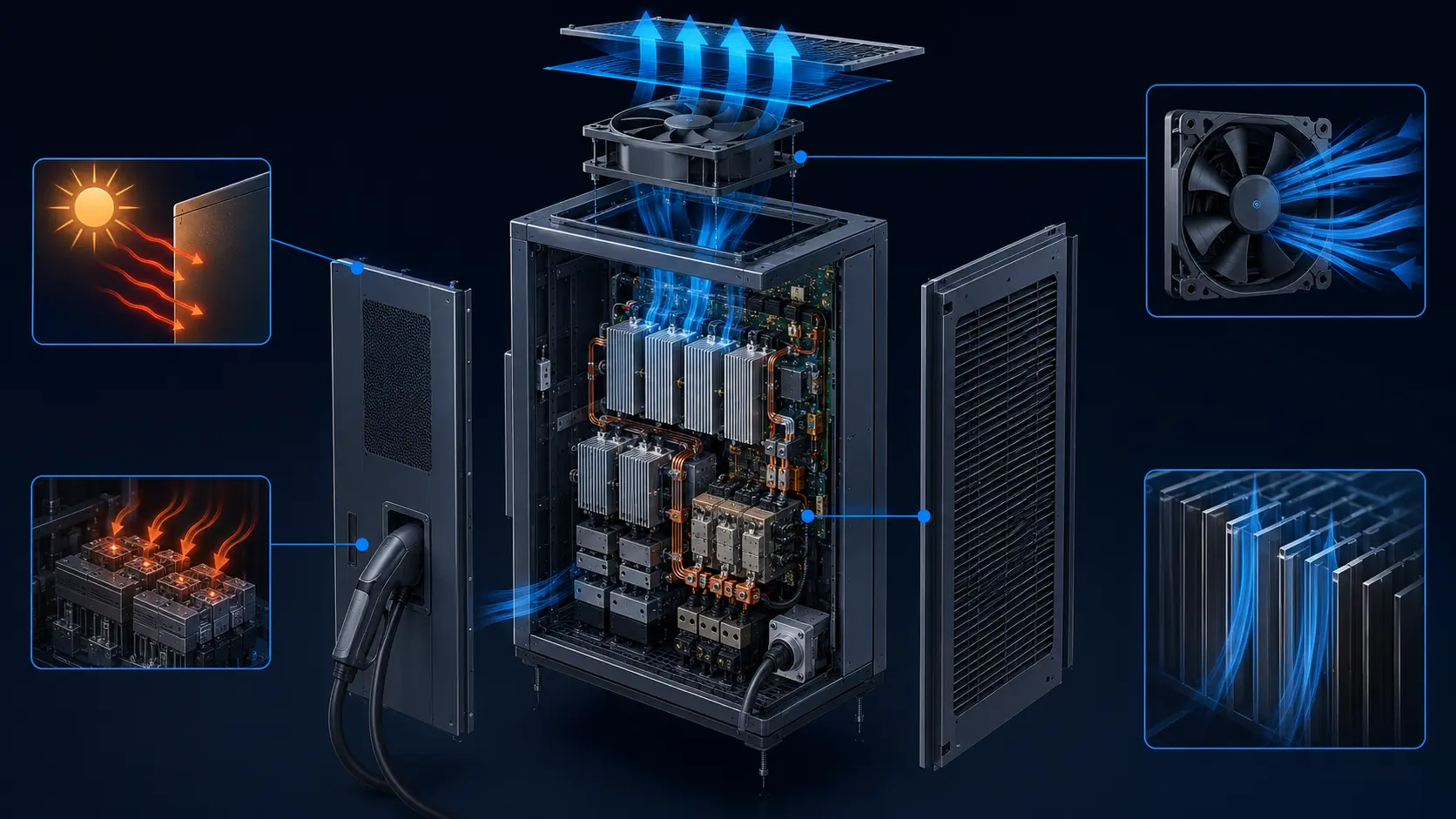
Thermal sizing failures rarely come from misestimating module loss alone. They come from failing to build a heat balance. A useful first model separates power modules, transformer and AC input stage, inductors and busbars, auxiliary electronics, cable and connector losses, and environmental gains. For example, if a 200 kW design is assigned a provisional 2–3% module-loss budget, that is 4–6 kW; it is an engineering estimate for the model, not a universal charger efficiency rule. Confirm every term with vendor data or measurement.
The cable and connector are a separate thermal boundary. Their resistive loss follows P = I²R, so current matters disproportionately: doubling current increases the same-resistance loss by four times. A 500 A CCS2 system may need liquid-cooled cable hardware, but the actual handle loss depends on conductor resistance, connector design, duty cycle and cooling. That deserves its own section below.
Then add the environment. Solar gain can be estimated with Q_solar = α × G × A, using the surface absorptivity, site irradiance and exposed area; do not reuse a fixed W/m² value without checking orientation and climate. Use the project's design-ambient methodology, such as the applicable ASHRAE design condition, and measure or model recirculation because local component temperatures can be materially above bulk cabinet air.
| Factor | Typical error | Why it bites |
|---|---|---|
| Solar gain | Ignored entirely | Calculate α × G × A for the actual site, orientation and finish |
| Ambient design temp | “Average summer” rather than ASHRAE 0.4% value | Use the selected design condition, not an informal seasonal average |
| Internal recirculation | Assumed uniform cabinet | Local component temperatures can exceed bulk air; verify with sensors or CFD |
| Cable and connector | Counted as part of cabinet loss | I²R loss rises rapidly with current; verify cable and connector limits separately |
The cable derates before the cabinet does
The most overlooked thermal limit at a high-power site is the length of copper between the cabinet and the car.
Cable current capability is not a single number. It depends on conductor size, connector temperature, ambient, duty cycle, jacket construction and whether the assembly is air- or liquid-cooled. CharIN materials describe liquid-cooled cable assemblies in high-power CCS applications, and current industry solutions extend into 500 A and higher ranges. That does not make every 500 A cable interchangeable: the charger, connector, cable and vehicle inlet must be evaluated as one system.
The weight and handling trade-off matter as much as temperature. More copper reduces resistive heating but increases stiffness and operator force; liquid cooling can reduce the conductor and jacket burden, while adding a pump, coolant path, sensors and maintenance requirements. Specify a cable by continuous current, ambient, duty cycle, bend radius, connector temperature and fault response rather than by peak current alone.
The practical test is a sustained session at the intended current and worst site ambient. Log conductor or connector temperature, coolant flow where applicable, charger output and any protective derating. If the cable reaches its limit before the cabinet, the fan selection cannot fix the system; if the cabinet is the limit, a higher-pressure fan module or a different thermal architecture may be required.
Air or liquid: where each one stops working
The cooling architecture scales with current, heat load, enclosure volume and service conditions, not just the charger nameplate. Forced air can be practical when the heat load, pressure drop, ambient and acoustic limit fit the cabinet; liquid cooling becomes attractive when sustained current, cable temperature or module heat flux leaves too little margin. There is no universal air-cooled power ceiling, so compare architectures using continuous output at the deployment site's design ambient and duty cycle.
Liquid cooling moves heat at the module or cable interface through cold plates, a coolant loop and a heat exchanger. It can support higher continuous current, but it also adds pumps, hoses, sensors, coolant compatibility and maintenance points. The choice should be based on measured thermal resistance, reliability targets and service capability, not on a generic claim that liquid is always better.
Air remains a valid, lower-cost choice when the cabinet can reject its measured heat load with acceptable pressure drop, noise and filter-service intervals. Choose based on sustained current at worst ambient, not the station's peak power. For higher-current cable assemblies, CharIN documents liquid-cooled solutions in the CCS ecosystem; the charger supplier still needs to validate the complete charger-cable-vehicle system.
Noise is the tiebreaker some site designs forget. Moving several kilowatts of heat with fans can require large, fast fan banks, making sound pressure a real constraint for urban curbside chargers, hotel forecourts and residential-adjacent sites. Variable-speed fans tied to measured module temperatures can reduce unnecessary noise, while the fan control must still guarantee airflow at the worst filter and ambient condition.
Whichever architecture you choose, hold it to a field-testable standard rather than a datasheet claim: measure temperature rise per kilowatt at the selected design ambient, record output during continuous load, review pump or fan life against the site's duty cycle, and request derating curves under loaded-filter or reduced-flow conditions.
| Cooling approach | Typical current | Notes |
|---|---|---|
| Passive air | Project-specific | Use only when measured heat load, pressure drop and ambient leave margin |
| Forced air (vented IP54) | Project-specific | Requires high static pressure through packed modules and a filter-service plan |
| Liquid cooled | Often used at higher current | Validate continuous current, junction temperature, coolant flow and derating |
If you stay air-cooled, the fan needs pressure, not just CFM
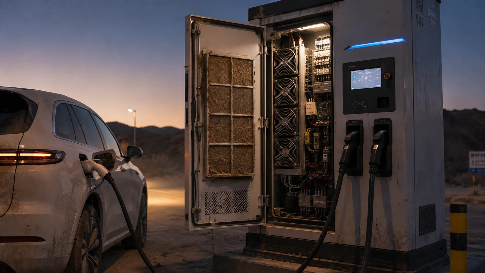
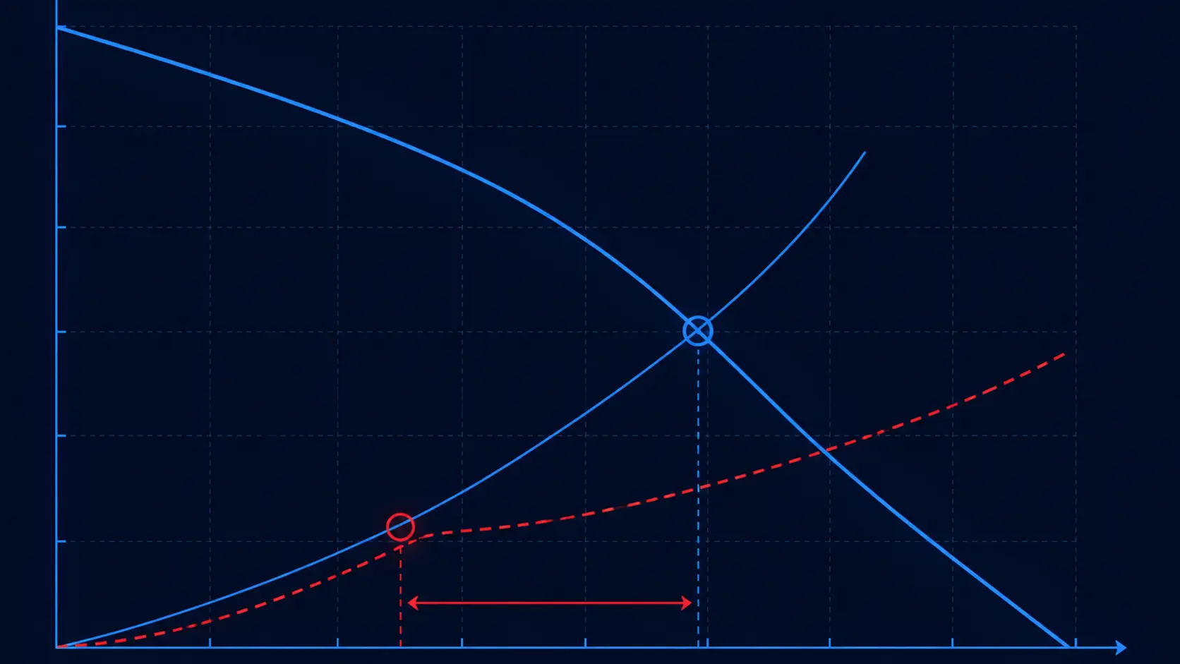
Many DC fast chargers use vented, filtered cabinets with forced air, although the enclosure rating and airflow architecture are product-specific. Here fan selection is decided by static pressure, not free-air CFM. The power modules are packed tightly and the air path is often ducted through heat sinks and grilles, so a high-airflow fan with little pressure will stall while a higher-pressure fan moves the same air through the impedance. Filters add a second moving target: as they load with dust over months of 24×7 service, system pressure rises and the operating point slides toward lower flow exactly when summer ambient peaks — so select the fan with margin above the clean-filter duty point and trigger filter service on measured airflow or fan speed, not the calendar.
For this class of cabinet, large high-static-pressure DC axial fans are the practical starting point. MEGA Tech's catalogue includes 172 mm and 200 mm DC axials sized for exactly this kind of ducted, restrictive airflow.
- MG17251HV48X — 172×150×51 mm, 48 V, about 361.7 CFM at 45.4 mmH2O: high static pressure for flowing through densely packed power modules.
- MG20060VHH48X — 200×200×60 mm, 48 V, about 645.6 CFM at 22.0 mmH2O: higher total airflow where inlet restriction is moderate.
- Dual ball bearings across these series suit an outdoor 24×7 duty; confirm PWM, FG/RD feedback and the IP rating for the selected build.
- Where the enclosure must stay sealed to IP65+, a fan cannot cool the air below ambient — a sealed cabinet with high module loss calls for a closed-loop cabinet air conditioner, not a bigger fan.
Size with margin, then service it as a replaceable module
Over-specify the cooling before you tool the enclosure. A practical engineering starting point is to reserve a documented margin above the calculated heat load, then validate the airflow with a CFD pass or prototype measurement before committing to tooling. The margin should be justified against uncertainty in efficiency, solar gain, filter loading and ambient rather than treated as a universal multiplier. Site design is part of the same budget: orientation, shading and cabinet finish all affect the enclosure heat balance before a single fan is chosen.
Maintainability matters as much as the first build. Charger sites are serviced in the field, often against walls with only front access. Designing the power stack around modular, slide-out blocks can shorten repair time, but the actual improvement must be measured for the chosen service procedure. Specify front access, fan-tray replacement, filter access, connector inspection and fault logging as explicit maintenance requirements.
Zone the enclosure's protection rather than sealing everything to one heavy rating: a typical split is IP67 at the cable entry and IP54 for the power bay, keeping dust and moisture away from electronics without locking in all the heat.
Finally, treat the fan bank itself as a monitored, redundant subsystem. An N+1 arrangement lets the cabinet derate gracefully instead of tripping when one fan fails, FG/RD tachometer feedback turns a stalled or slowing fan into an alarm in the site's monitoring system rather than a silent hot-spot discovery a week later, and front-access fan trays mean the swap happens in minutes during a session gap. In a station whose revenue is uptime, a fan that can report its own health is part of the availability design, not an accessory.
Turn the charger heat load into a tested fan module
A fast-charger cabinet needs more than a high-CFM fan: it needs a configuration built around the module, filter, enclosure and site duty cycle.
MEGA Tech can work with charger manufacturers from the first thermal requirement. We review the power-module losses, heat-sink path, filter and grille pressure drop, ambient range, dust or salt exposure, noise limit, voltage, control signal, available space and service access. That turns the cabinet's sustained output target into a fan specification that can be measured rather than guessed.
The fan module can be customized around frame size and thickness, airflow and static pressure, speed range, 12 V, 24 V or 48 V electrical requirements, PWM control, FG or RD feedback, connector and cable length, bearing choice, rotation direction, mounting and environmental protection. This is especially useful for new charging equipment and regional variants where the standard imported fan assembly is too expensive, unavailable or not matched to the actual cabinet path.
We can build a practical sample for the customer's cabinet or a representative fixture, then test clean and loaded filters, hot ambient operation, noise, control response, fault feedback and continuous running. After the fan is matched to the charger, the approved configuration can move into reliable volume production with consistent performance and a repeatable replacement plan.
- Start with sustained heat load, pressure loss, ambient, noise and service targets.
- Customize fan size, voltage, control, feedback, wiring, bearing and mounting details.
- Validate the sample with actual cabinet restrictions, loaded filters and hot ambient conditions.
- Move the approved fan module into stable, cost-conscious production.
Engineer FAQ: EV Fast-Charger Heat Rejection and Fan Selection
A charger cooling design should be validated against sustained output, site ambient, enclosure resistance and service conditions rather than peak efficiency alone.
Q: Is 7.5 kW the heat loss of every 150 kW fast charger? A: No. It is an illustrative calculation for 150 kW at 95% electrical efficiency: 150 kW x 5% = 7.5 kW. The real loss includes the actual efficiency curve, power modules, magnetics, cables, connectors, auxiliaries and environmental gains at the selected load and temperature.
Q: How should charger thermal load be converted into a fan requirement? A: Build the heat balance first, including module, transformer, magnetics, cable, auxiliary and solar gains. Calculate a first airflow from the allowable temperature rise, then select the fan where its P-Q curve intersects the complete cabinet system curve with clean and loaded filters.
Q: Why can a charger deliver less power on a hot day even when its fans are running? A: Module, capacitor, connector or cable temperatures can reach protection limits while the rotor still turns. Use output-versus-ambient and output-versus-time data, and monitor component or internal-air temperature, fan speed, airflow or pressure and derating state together.
Q: Is liquid cooling always better for a high-power charger? A: No. Liquid can help when sustained current, cable temperature or module heat flux exceeds the practical air-side margin, but it adds pumps, hoses, sensors, coolant compatibility and service points. Compare the complete architecture at the required duty, ambient, reliability and maintenance conditions.
Q: Should an air-cooled charger fan be selected by maximum CFM? A: Not alone. Filters, heat sinks, grilles, cable paths and packed power modules can create substantial resistance. Select from the fan P-Q curve at the installed operating point, then verify the loaded-filter condition, inlet temperature, noise, power and control response.
Q: Does an IP54 or IP67 label prove that the charger cooling design is adequate? A: No. Ingress protection and thermal performance are related but different requirements. A more sealed cabinet can increase pressure drop or reduce natural heat rejection. Validate the complete enclosure, fan, filter, cable entries, glands and service panels for both environmental protection and sustained thermal output.
Q: Are dual-ball bearings automatically the right choice for every outdoor charger? A: No universal bearing choice applies. Compare the selected bearing, grease, temperature, speed, orientation, contamination, vibration, duty cycle, noise and documented life data for the actual fan. Confirm the required environmental and control behavior on the representative charger.
Q: What should a customized charger-fan sample prove before production? A: Use the real or representative cabinet, heat sinks, grille, filter, cable path, controller and mounting. Test sustained output at design ambient, loaded filters, start-stop and fault conditions, recording airflow, pressure, module and connector temperatures, RPM, current, noise, PWM or FG/RD behavior and derating response.
- Tie every numerical answer to voltage, speed, temperature, mounting and test condition.
- Separate catalogue maximums, engineering estimates and measured application results.
- Use the FAQ to define the next measurement or sample-validation step.
Final review checklist
A charger's cooling decision is a sustained-output decision. Verify it against the deployment, not the datasheet.
- Is the required airflow sized against all four heat sources (modules, transformer, magnetics, cable) plus solar gain, with a documented uncertainty margin?
- Was the ambient design temperature taken from ASHRAE 0.4% values, not an average summer figure?
- Has the vendor's derating curve been reviewed at your site's worst ambient — since curves are not standardised between vendors?
- At high power, has the cable been treated as a separate thermal limit — jacket start temperature, current rating and liquid-cooling options?
- Is the fan selected for static pressure through the module path — and a vented IP54 design — rather than free-air CFM?
- Is the enclosure zoned (e.g. IP67 cable entry, IP54 power bay) instead of sealing everything?
- Is the fan rated for 24×7 duty with dual ball bearings and replaceable access?