
The inverter kept derating itself in the middle of third shift
It was not a power fault, and not something the electrician could fix with a meter. The drive simply ran hot when the plant was busiest, cut its own output to protect itself, and cost a full shift of production — twice in one month — before anyone counted how long the fans behind the service panel had been ignored.
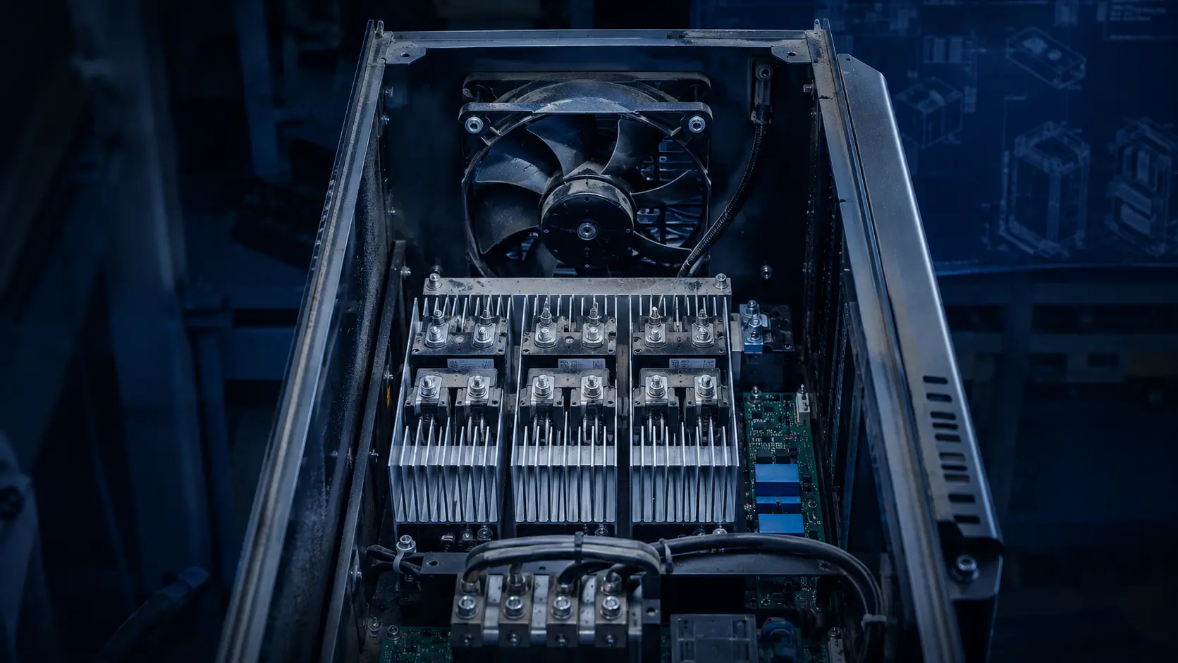
Consider a representative power rack on an extruder line: dense IGBT-based drive modules, a control stack, and two cooling fans at the rear that nobody had touched since install because they were behind a service panel nobody opens on a good day. When the drive derated, the SCADA log showed a fan-fault flag the maintenance team had never seen before — so they cleared it and reset. The drive re-ran hot and faulted again within the week.
This is a common engineering failure pattern, and it is not always a story about a bad fan. Overtemperature risk is strongly affected by the installation: clogged filters, degraded fans, hot intake air and blocked airflow can all remove the thermal margin. It is a story about selecting a fan by the wrong number, then letting a dusty, vibrating, 24-hour environment do the rest.
The teardown below is how the plant's team found the real cause — and why the fix was a different fan and a different control habit, not a better filter.
The number on the spec sheet was the lie
The original fans were picked for the free-air CFM printed on the distributor's product page — the airflow a fan moves with no enclosure at all, a vacuum rating no installed device ever sees. In a real rack, a dense power stack, a dust filter and a bundle of wiring are all restrictions, and each one pushes the fan up its own pressure-versus-flow curve, away from that headline number.
The result is a predictable system effect: once filters, heat sinks and components are added, the installed airflow can be far below the free-air catalogue value. The exact reduction depends on the fan curve and system resistance, so measure or calculate the operating point. In this cabinet, the drive's own heat sink was the largest single restriction and the intake filter was second.
So the fans were moving a fraction of the airflow the thermal design assumed. They spun at full speed trying to keep up, which pulled in more dust, which clogged the filter further, which raised the system resistance again. The cooling — and the derating — spiralled. Industry troubleshooting guides rank clogged filters as the single most common cause of VFD overtemperature trips, ahead of fan failure itself, and this cabinet was a textbook case.
There is a second number the plant never checked: intake air temperature. Many industrial drives use a 40°C reference condition, but the permitted temperature and derating curve are model-specific. ABB drive documentation, for example, publishes a defined current derating curve above its rated ambient; other manufacturers can use different limits. The wall thermometer in the electrical room read 31°C; the air six inches from the extruder's hot ductwork, feeding the drive's intake, was another story entirely. The measurement that matters is not the room. It is the air actually entering the cooling path.
Dust and vibration do the rest
The dust was not just a filter problem; it was a bearing problem. Fine contamination settling on the blades unbalances the impeller, and an out-of-balance fan vibrates, and that vibration is what wears a cheap bearing out early. This machine sat on a vibrating extruder line, so the fans were being hammered from both directions at once — contaminated air on the intake, mechanical shock through the mounting feet.
The drive's temperature controller made it worse in a quieter way: it ran the fans at full speed continuously rather than ramping them with load. Constant full-speed operation pulled maximum dust through the intake and loaded the bearings around the clock, in a plant that only needed full cooling during the heavy extrusion cycles.
Bearing class is where this decides itself. Fan life depends on bearing system, internal temperature, speed, contamination, vibration and duty cycle; a clean-room catalogue L10 value cannot be copied into a dusty, hot cabinet. A fan with robust double ball bearings may provide more margin for this site's stress, but the supplier should state the test condition and the design team should validate the chosen life at the actual operating point. The bearings were the mechanism behind the 'mystery' fan-fault flag.
And the dust worked on the heat sink directly. A fin pack coated in fine particulate acts as an insulating blanket between the aluminum and the air — field troubleshooting guides from hot-climate installations describe sand and dust buildup that blocks heat flow no matter how hard the fans work. The same teardown found the thermal interface compound between the IGBT modules and the extrusion had dried and crumbled at the edges, another quiet degradation that no alarm watches. Heat-related failures like these develop gradually, which is exactly why they arrive as 'mystery' deratings instead of clean faults.
The capacitor angle deserves its own sentence, because it is the bill that arrives years later. DC-link electrolytic capacitors age with temperature, but the life multiplier depends on capacitor construction, ripple current, applied voltage and the manufacturer's calculation method. A drive that spends a year running warm because its fans deliver less air than intended is consuming thermal margin and potentially capacitor life. The derating events are the visible cost; the shortened component life is the deferred one.
The alarm that never had a chance
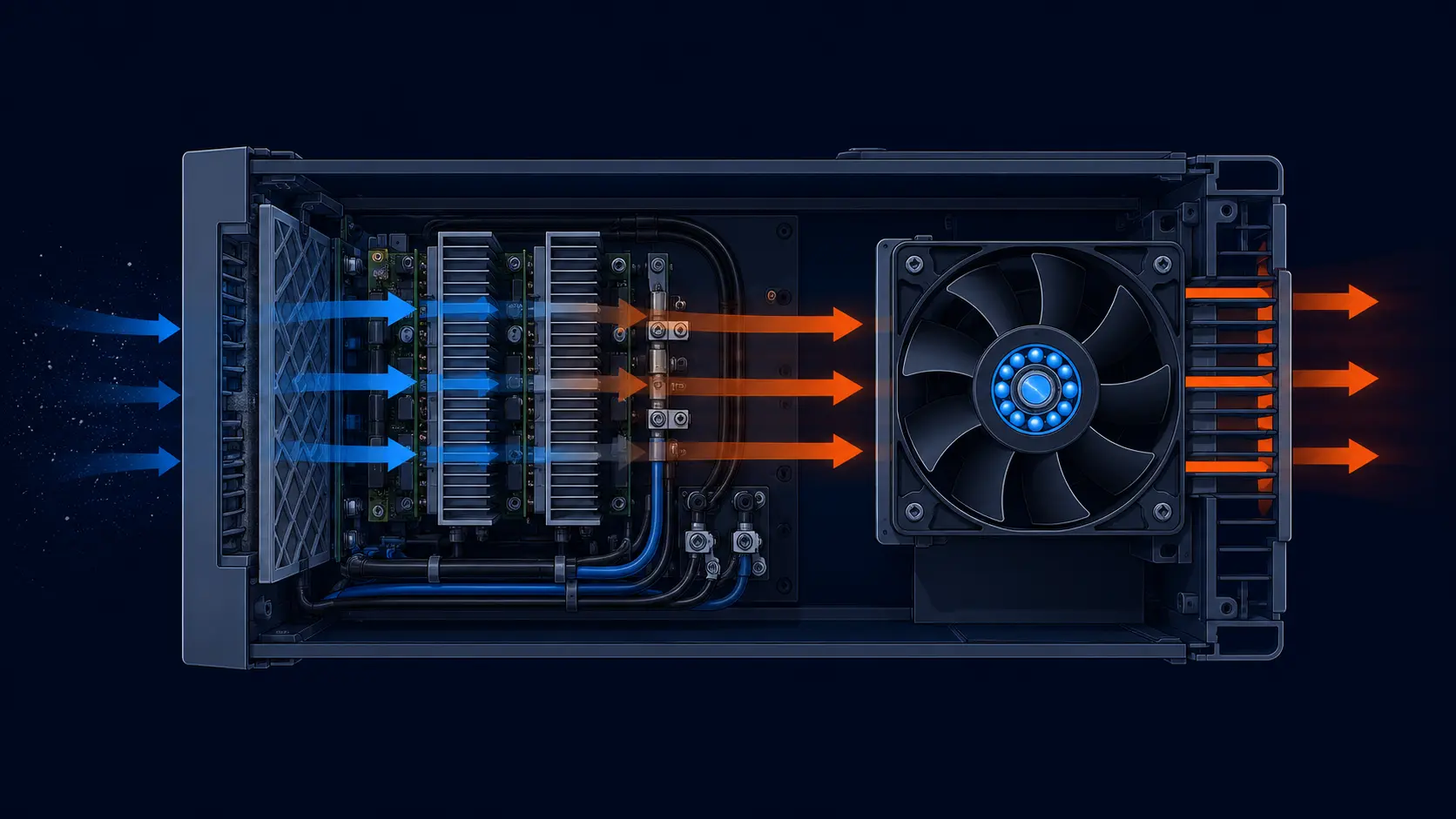
Here is the part of the post-mortem that stung the most. The drive did have fan monitoring — the SCADA flag proved it — but the flag appeared once, weeks before the first derating event, and never again. That is not a coincidence. A fan that fails outright and stops is easy to detect. A fan that slows gradually as its bearings wear, still spinning at 'plausible' speed, is exactly the failure mode drive protection routinely misses: industry troubleshooting notes describe it plainly — when a fan simply slows down from bearing wear, the drive may not catch it at all, and you just see overtemperature trips that get worse over time.
By the time the drive's heat-sink sensor crossed its trip threshold, the cooling chain may have been degrading for months. The threshold, sensor location and fault code are manufacturer- and model-specific, so the drive manual and measured trend should be used instead of a generic temperature number. The fault log told the maintenance team when the drive gave up; it never told them when the fans started dying.
The fix that costs nothing at design time: specify fans with a tachometer (FG) or rotation-detection (RD) output wired to the controller, and alarm on underspeed — a speed band below expected RPM at a given PWM command — not just on stall. Speed feedback that reports 'the fan is turning' is nearly useless against this failure mode; speed feedback that can be trended week over week catches a bearing losing a step before the heat sink ever feels it.
That single wiring decision converts the most common drive fault in the field from a production-loss event into a scheduled maintenance line item.
The replacement was picked by pressure, not by CFM
The plant's fix started from the numbers it should have used first. Its project measurement found that the filter plus drive heat-sink path demanded about 127 Pa (approximately 12.95 mmH2O) of static pressure at the required airflow — a site-specific result, not a universal VFD threshold. At that resistance, the original fans had been operating near their knees, delivering a trickle.
The fan that fit the mount and met that pressure was a high-static-pressure axial with ball bearings, sized for the drive's 24 V bus. At its operating point it delivered the airflow the drive actually needed, and its stiff pressure curve meant dust building up on the filter no longer stalled the airflow the way it had with the original fans — there was margin left between the clean-filter and dirty-filter operating points.
Temperature control was the second half of the fix. The drive's controller was reconfigured to ramp fan speed with heat-sink temperature and load, so the fans idled at low speed through light loads and came up only under real heat. Less dust pulled in, bearings loaded less, acoustic noise dropped on night shifts — and the rear panel stayed quiet enough that a technician could finally hear a shaft complain before it failed.
- MG8038HV24X — 80×80×38 mm, 24 V, 129.22 CFM at 127 Pa (5.00 inH2O) in the current catalogue row: a high-pressure class for pushing through dense drive heat sinks and filters. Confirm the exact operating point from the full P-Q curve.
- MG12025HH24X — 120×120×25 mm, 24 V, ~107 CFM at 5.04 mmH2O and 3,000 RPM: a roomier, lower-speed option for a rack whose measured resistance is materially lower than the project example.
- MG4056HH12B — 40×40×56 mm, 12 V, ~31 CFM at 64 mmH2O: a compact high-pressure blower for the tightest corner of a machine or panel.
- Confirm ball-bearing construction, the operating-temperature range and PWM control with engineering before tooling the bracket — they decide how long it survives this cabinet.
The airflow path is the second spec sheet nobody reads
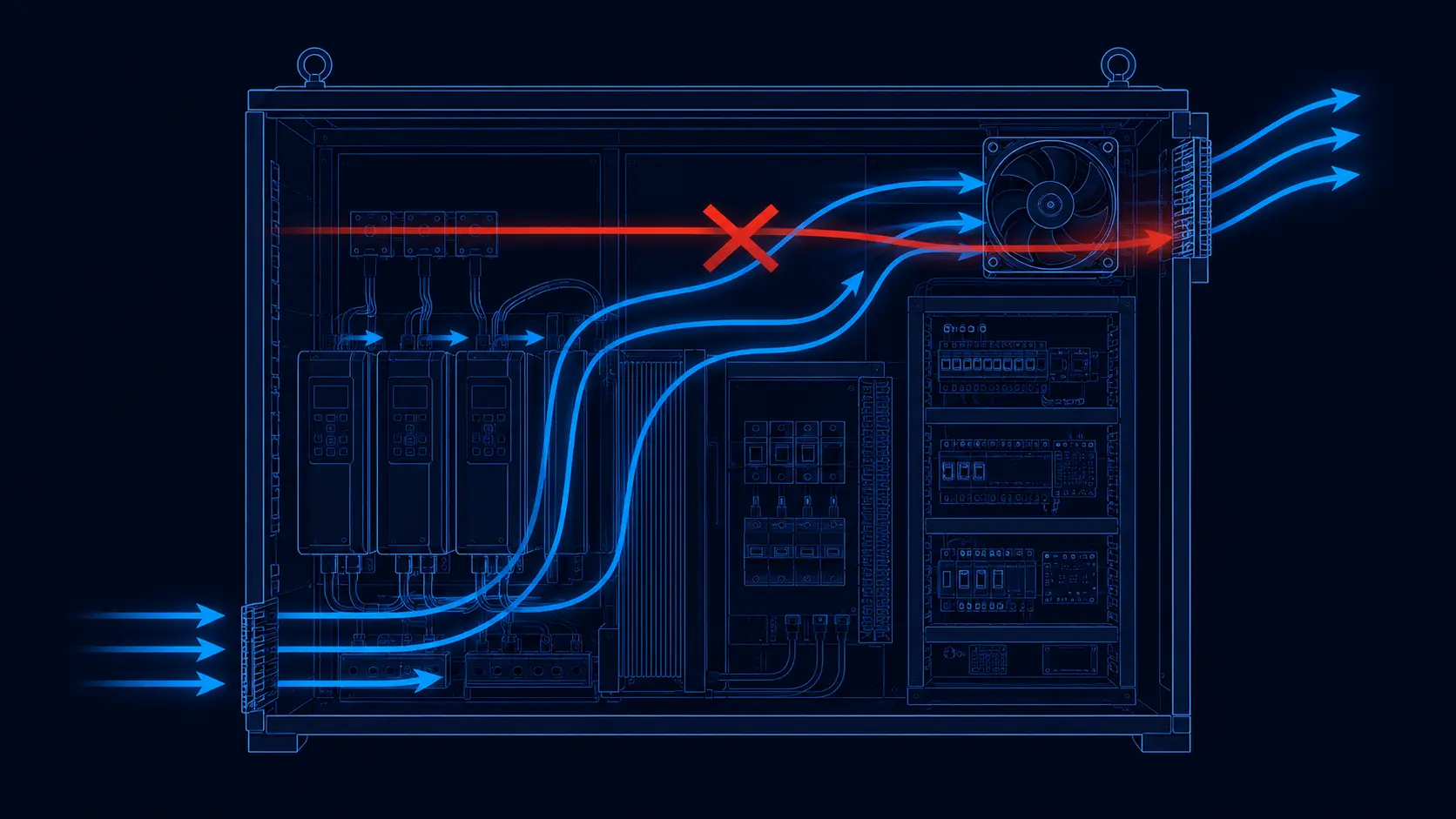
A high-pressure fan is not a licence to ignore the cabinet. Once the plant had a fan that could push through the restriction, it went back and took real airflow measurements at the drive's heat sink with a smoke pencil — and found the classic pattern of a cooling path drawn by instinct: intake and exhaust on the same side, so most of the air short-circuited from inlet to outlet without ever crossing the modules that were getting hot.
They re-routed it so cool air entered low, swept up through the drive's heat sinks and the control stack, and left high on the opposite corner, with baffles keeping the one-way path honest. The measured airflow over the hotspots roughly doubled without any change to fan size. In a factory, that cheap correction is often worth more than a bigger fan.
Two site factors rounded out the picture. First, filtration: the intake filter is often a major pressure drop in the path, and over-filtering to chase an IP rating can starve the very cooling it protects — this plant moved to a positive-pressure arrangement so dust is pushed out at leaks rather than drawn in. Second, altitude: lower air density changes both fan performance and heat transfer. Apply the selected drive manufacturer's altitude and ambient correction rather than a universal percentage, then validate the fan at the reduced-density operating point. Oversizing the fan to hold that margin is standard practice, not paranoia.
What the post-mortem changed on site
After the swap, the site should verify the result across a representative hot-duty period rather than infer success from one restart. The fan seats were put on a scheduled inspection plan: visual checks and filter service based on dust loading, periodic airflow and infrared checks on the heat sinks, and a controlled deep clean with the power locked out. The interval belongs to the site environment and measured trend, not to a universal calendar.
The numbers that used to be checked informally were now written down and trended: actual airflow at the heat sink, pressure drop across the filter, fan speed at a known PWM command, and running hours per bearing family. The plant also put a spare fan kit on the shelf for every drive it could not afford to take down. When a fan is trending slow, it gets swapped on a planned stop, not during a breakdown.
One habit the plant added costs almost nothing and pays forward: trend the electrical fingerprints of heat. Log heat-sink temperature, fan RPM and DC-bus ripple over time, then interpret each trend against the drive and capacitor manufacturer's limits. A slow drift in fan speed at a fixed command can indicate a wearing bearing; a change in bus ripple can indicate capacitor or load changes and should be investigated, not assigned to one cause automatically. Reviewed at a defined interval, those curves can turn the next 'mystery derating' into a scheduled work order before the drive trips.
The bigger lesson applies to every cabinet like this one: a fan is not a part you select once with a free-air number and forget. It is a system element sized at its real operating point, instrumented so its decay is visible, specified for the dust and vibration of its site, and managed for the life of the machine.
Design the replacement around the cabinet
A VFD replacement fan should be developed from the cabinet's real pressure, temperature, dust and vibration conditions.
MEGA Tech can support industrial-equipment teams by converting those conditions into a practical fan specification. We review the heat-sink path, filter pressure drop, intake temperature, mounting envelope, voltage, PWM or FG/RD requirements, noise limit, vibration exposure and expected 24/7 duty before recommending a fan platform.
If a standard model does not provide the right combination of pressure, airflow, size or control, we can develop a customized sample around the drive cabinet: higher pressure margin, different frame or thickness, bearing selection, speed range, PWM response, rotation feedback, connector, cable length, mounting details and environmental protection. This gives OEMs and smaller machine builders a way to solve the thermal problem without accepting a high-priced international replacement as the only option.
The sample should be tested in the actual cabinet or a representative fixture with the real filter, heat sink and airflow path. We verify temperature, airflow, pressure, noise, RPM feedback and continuous-duty behaviour, refine the design with the product team, and then carry the approved specification into reliable volume production.
- Measure the cabinet's real operating point before selecting the replacement.
- Customize pressure, bearing, control, wiring and mounting details for the machine.
- Validate the fan with the real filter, heat sink and airflow path.
- Transfer the approved sample into stable, cost-conscious production.
Engineer FAQ: VFD Cabinet Fan Derating
A VFD cooling fan should be selected and monitored against the loaded cabinet condition, not the clean bench condition.
Q: Why can a VFD overheat even when the fan is still running? A: A loaded filter, blocked heat sink, hot intake or worn bearing can reduce useful airflow while the rotor still turns. Check the installed pressure drop, airflow, heat-sink temperature, speed and current together.
Q: Is 127 Pa (12.95 mmH2O) a standard VFD fan requirement? A: No. That value belongs to the project measurement described in this article. The required pressure must be calculated or measured for the actual filter, heat sink, grille, wiring and airflow target.
Q: Should I select a fan by maximum CFM or maximum pressure? A: Neither endpoint is enough. Use the fan P-Q curve and the cabinet system curve to find the installed operating point, then check clean and loaded-filter conditions at the actual inlet temperature.
Q: Does FG or RD prove that the cabinet has enough cooling? A: No. These signals can show speed or a defined fault state, but they do not directly measure airflow through a loaded filter. Pair them with a healthy baseline, temperature trend and an acceptance limit for underspeed or airflow loss.
Q: What should be included in a replacement-fan sample test? A: Use the real or representative drive cabinet, filter and heat sink. Record pressure, airflow, heat-sink temperature, inlet temperature, voltage, RPM, current, noise, PWM response and fault behavior across normal, peak-load and maintenance conditions.
- Tie every numerical answer to voltage, speed, temperature, mounting and test condition.
- Separate catalogue maximums, engineering estimates and measured application results.
- Use the FAQ to define the next measurement or sample-validation step.
Final review — the questions that catch this case
If you can answer all seven without needing a fresh measurement, your cabinet will not be the next fan-fault derating in the log.
- Was the fan sized at its operating point with filter + heat-sink pressure drop, not free-air CFM?
- Was the intake air temperature measured at the drive's intake, not the room thermostat — with the manufacturer's ambient and altitude derating applied?
- Does the fan hold enough static pressure to keep pushing through a dirty filter, not just a clean one?
- Are the bearings appropriate for the site's dust, vibration and 24/7 duty — with a replacement interval justified by measured trend and supplier life data, not run-to-failure?
- Do the fans report FG/RD speed to the controller, with an underspeed alarm trended over time — not just a stall alarm?
- Does the temperature controller ramp speed with heat-sink temperature and load instead of running full speed continuously?
- Is the airflow path in low and out high and opposite, with baffles, so air actually reaches the hot modules instead of short-circuiting?
