
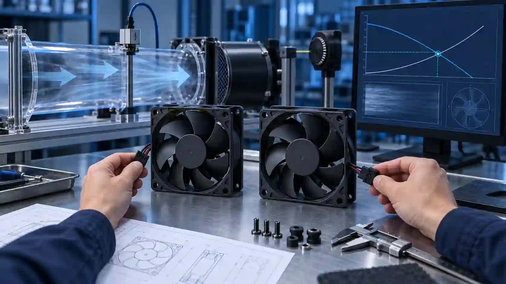
A Premium Fan Replacement Is an Engineering Comparison
A replacement fan can match the frame and voltage and still fail the product. The real question is whether it delivers the required air, pressure, control response, noise and life at the installed working point.
Engineers often begin a replacement search with a familiar part number from Sanyo Denki, SUNON, Delta, NMB, ebm-papst or another established supplier. That is a useful reference, but it is not yet a replacement specification. A 120 x 120 x 38 mm, 24 V fan can have a very different pressure curve, power draw, acoustic profile, bearing construction or tachometer response from another fan with the same headline dimensions.
The safe way to reduce cost is to preserve the functions that matter to the product and verify them under the same conditions. MEGA Tech can use the current fan as a benchmark, develop a compatible sample and tune the configuration around the customer's enclosure, rather than promising that a catalogue number is automatically interchangeable.
This article gives a practical screening method for a premium fan replacement: first identify the installed operating point, then compare the complete interface, then validate the sample in the real or representative assembly. Any cost benefit comes after the thermal and reliability requirements are confirmed.
Why Maximum CFM Is a Weak Replacement Test
Maximum airflow is a free-air endpoint. Most products do not operate at that endpoint.
A fan curve relates airflow to pressure. The enclosure, heat sink, filter, grille and duct create a system-resistance curve. The actual operating point is where the fan curve and system curve intersect. AMCA explains the same relationship in its fan-system guidance, and ebm-papst describes the operating point as the intersection of the fan and system curves.
That means a replacement with a similar free-air CFM can deliver a different installed result if its pressure curve is shallower. Conversely, a fan with a lower free-air headline can be the better replacement if it holds the required flow at the product's resistance. The comparison must therefore include at least one or more points around the expected operating point, not only maximum CFM and maximum static pressure.
For a first screening estimate, engineers can model a simple system curve as delta P = k x Q^2, then refine k using pressure-drop data or a measurement of the populated product. This is a screening model, not a substitute for a final assembly test. Filters, sharp transitions, blocked inlets and fan-to-fan spacing can change the result.
- Record the current fan's airflow and pressure at the intended operating point.
- Compare the candidate's P-Q curve at the same voltage and speed condition.
- Include filter, grille, heat sink, duct and enclosure losses in the system curve.
- Do not treat free-air CFM as installed airflow.
- Check that the selected point is not close to an unstable or rapidly changing part of the curve.
One Frame Size, Two Different Fans
Two candidates can fill the same cut-out, run at the same speed and share the same free-air airflow number, and still deliver different cooling. The shutoff pressure - and the whole shape of the curve between the endpoints - is what differs.
The figure below shows one enclosure, two candidates. Both fans reach 60 CFM in free air, so a datasheet comparison at the endpoints calls them equal. Inside the product, the air path demands about 130 Pa at the 40 CFM the heat load needs. The shallow 180 Pa curve settles where it crosses the system curve, near 37 CFM - below the target, so the fins run starved. The steeper 320 Pa curve, in the same frame, crosses higher on the same system curve and settles near 43 CFM, above the target with margin.

The Replacement Comparison Matrix Engineers Actually Need
Use the current premium fan as the reference configuration, then compare every field that affects the product rather than only the mechanical outline.
A good replacement review is a controlled comparison sheet. The source may be an official manufacturer page, a catalogue curve, a drawing, a customer measurement or a sample test. Keep those evidence types separate. A catalogue maximum is not the same as an installed acceptance value, and an estimated value is not a validated result.
The table below is a screening template. It intentionally does not invent a universal replacement row for any brand. The values for the current fan should be filled from its exact part number and revision; the candidate must then be measured or confirmed against the same requirements.
| Field | Reference fan | Candidate sample | Release gate |
|---|---|---|---|
| Frame / thickness | Exact drawing and mounting holes | Same envelope or approved adapter | Fits without blocking the intended air path |
| Voltage / power | Rated and operating range | Same supply and acceptable input power | No controller, fuse or connector overload |
| Airflow / pressure | P-Q curve at the product condition | Candidate curve at the same condition | Meets required operating point with margin |
| Speed / control | PWM, FG/RD, locked-rotor and restart behavior | Same signal logic and usable control range | System controller reads and commands it correctly |
| Noise | Method, distance, speed and assembly | Measured in the same setup | Meets product acoustic limit, not only catalogue dB-A |
| Life / environment | Bearing, temperature, dust and duty cycle | Equivalent or approved construction | Documented for the actual duty and environment |
| Mechanical details | Connector, cable, rotation and mounting | Matched or explicitly approved change | No rubbing, cable conflict or vibration issue |
PWM and Tach: the Interface the Controller Already Depends On
The electrical interface is where same-frame replacements fail silently. The product controller was validated against the original fan's signals, and it notices when those signals change.
On the common 4-wire interface, the controller sends a PWM speed command and the fan returns a tachometer pulse train. The Intel 4-wire PWM fan specification defines the numbers most designs inherit: a control frequency of 21 to 28 kHz with 25 kHz nominal, a tach output of 2 pulses per revolution on an open-collector pin, and full speed as the fail-safe when the PWM line is open. A candidate whose PWM input draws differently, whose tach pulses at a different count per revolution, or whose usable duty range starts or ends elsewhere will misreport even while cooling correctly.
The practical failure has two faces. If the replacement turns slower than the speed range the controller expects, the health check can read the lower tach count as a stalled or missing fan: the product raises a fault and may ramp every other fan to full speed to compensate, which costs the noise and power savings that motivated the replacement. If the replacement idles correctly but skips the locked-rotor output or the automatic restart behavior of the original, a genuinely stopped fan can pass unnoticed. Why normal RPM does not prove cooling airflow covers the acceptance checks that separate a healthy signal from a healthy fan.
So the replacement review treats the interface as a specification, not a connector shape: pin order, signal levels, PWM frequency response, tach pulses per revolution, duty range at which the fan must run and restart, FG/RD output logic, cable exit and length. Verify each one against the customer's controller with the real harness before the sample goes near a thermal chamber.
Use Standards to Make the Data Comparable
The comparison is only useful when the measurement conditions are comparable. ANSI/AMCA 210 defines laboratory methods for reporting fan airflow, pressure, power, air density, rotational speed and efficiency. ISO 5801 provides standardized-airway procedures and measurement-uncertainty guidance for fan performance testing. These references do not turn every product test into an identical test, but they explain why the fixture, air density, speed and pressure definitions must be recorded.
The installed assembly still needs its own verification. ISO/TR 16219:2024 addresses system effects: performance measured in standardized airways can degrade when the fan is installed beside disturbing components or fittings. The exact geometry matters, so a replacement sample should be checked with the real grille, filter, heat sink, duct transition and clearance wherever practical.
For an engineering release, record the fan voltage at the connector, speed or control command, pressure taps, airflow instrument, ambient condition, acoustic method, mounting orientation and assembly state. Without those details, a difference between two data sheets may be a test-method difference rather than a real performance difference.
An Anonymised Test Case: 4,900 RPM Was Not Automatically a Bad Fan
A real project discrepancy shows why replacement validation must control the fixture before changing the product.
In an anonymised MEGA Tech evaluation, a customer measured a custom bracket axial fan at 4,900 RPM against a 5,300 RPM specification and internal test reference. The difference looked like a motor or controller problem until the test arrangement was reviewed.
The fan had been placed flat against a desk, blocking one face, and the reading was taken before the defined stabilized condition. The retest restored open airflow on both sides and allowed the fan to reach the specified test condition. The measured result returned to 5,300 RPM.
This is not a statement that every replacement fan will produce 5,300 RPM, and it is not an airflow guarantee. It is a useful replacement lesson: measure the reference and candidate with the same fixture, voltage, warm-up, instrument and air path before concluding that one fan is weaker.
The Mechanical Interface Can Be the Real Reason a Replacement Fails
Even when the P-Q curves are close, the replacement can fail mechanically. Check the fan's actual depth, mounting-hole pattern, inlet clearance, outlet transition, impeller overhang, cable exit and bracket stiffness. A small change in clearance can create rubbing, tonal noise or vibration when the product moves.
In another anonymised MEGA Tech project, a 45 x 45 x 10 mm centrifugal blower created abnormal noise during movement and vibration. The redesign enclosed the impeller and controlled the clearance around it. The published case reports no abnormal noise or contact in the revised configuration while retaining the original electrical and application requirements.
The project is a reminder that replacement engineering is not only a curve-matching exercise. The product must also survive its mounting direction, vibration, cable routing, thermal expansion and service conditions.
- Check the installed inlet and outlet area, not only the nominal frame size.
- Inspect impeller-to-frame and impeller-to-neighbour clearance under vibration.
- Confirm connector, cable exit, mounting preload and bracket stiffness.
- Repeat acoustic and thermal tests after any mechanical change.
- Freeze the approved drawing and interface before volume production.
When a Custom Variant Is Better Than a Drop-In Replacement
A drop-in replacement is not always the lowest-risk or lowest-cost engineering path.
If the existing premium fan is available but expensive, a compatible custom sample may preserve the mounting and control interface while adjusting the performance curve, bearing, connector, cable or environmental protection to the customer's actual product. If the existing part is no longer available, the same process can create a controlled alternative rather than a one-to-one visual copy.
The customization boundary should be explicit. Possible changes include frame and thickness, speed range, PWM response, FG/RD output, connector and cable length, rotation direction, bearing configuration, ingress protection and acoustic tuning. Each change must be checked against the thermal, electrical, mechanical and reliability requirement; it should not be described as equivalent until the relevant test evidence exists.
This is where MEGA Tech's custom-manufacturing model is useful. What we do: custom DC and EC axial fans and backward-curved centrifugal fans, selected against your installed operating point rather than a part number, with samples validated in your assembly. What we need from you: the required airflow and the static pressure at that airflow, the temperature and altitude basis, supply voltage and tolerance, the command, feedback and alarm interface, the connector and harness, the available space and mounting, the noise target with its measurement point, and the life assumption with its temperature basis. Where our boundary sits: we do not supply the enclosure, the controller, the cabinet safety design or the emergency ventilation function, and we will not call a fan equivalent because its outline drawing matches - the installed operating point decides.
- Start from the current fan part number and the product's real failure or cost driver.
- Define which functions must remain identical and which can be optimized.
- Build a sample with the required electrical and mechanical interface.
- Validate the installed operating point, noise, temperature, control and reliability conditions.
- Release the approved configuration only after the evidence matches the product requirement.
Questions for a Design Review
Bring the installed numbers, not the catalogue endpoints. These questions close a replacement review.
If you are evaluating a replacement now, send the current fan part number, frame and thickness, rated voltage, airflow path, estimated pressure resistance, control signals, noise limit, operating temperature and available samples. MEGA Tech can review the reference, develop a compatible custom sample, test it at the relevant working point and support the transition from evaluation to controlled production. If you do not have a complete system curve yet, send the enclosure drawing, the filter or grille details, the heat load and the problem you are trying to solve - a screening estimate and a defined next measurement are a valid first step.
- 1. What airflow and static pressure does the product require at the operating point, and what system resistance did you measure there?
- 2. Where do the reference fan curve and the candidate curve each cross that system curve, and is the crossing clear of the steep, unstable part?
- 3. Do PWM frequency response, tach pulses per revolution, FG/RD logic, locked-rotor output and restart behavior match what the controller was validated against?
- 4. What voltage, current and inrush does the candidate draw at startup and at full load, and do the supply, fuse and connector hold margin?
- 5. What acoustic level did each fan measure in the assembled product, at the same speed, distance and method?
- 6. What are the ambient rating, the L10 basis temperature and the ingress protection of each candidate, and what filter loading moves the operating point over the service interval?
- 7. Do frame, thickness, mounting, inlet clearance, outlet path and cable details fit without a new failure mode under vibration?
- 8. Which fixture, instruments and acceptance limits were used for reference and candidate, and is the approved configuration frozen for pilot and volume production?
