When Charging Power Drops, Do Not Blame the Fan First
A DC fast charger can derate even when every fan appears to be spinning normally. The limiting problem may be power-module loss, heat-sink contact, air bypass, filter loading or a control curve that reacts too late.
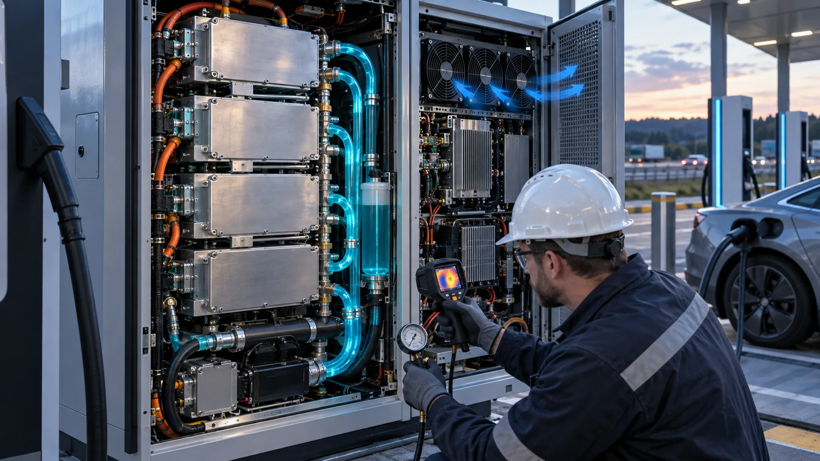
A high-power charger converts electrical energy through rectifiers, PFC stages, isolated DC-DC modules, contactors, busbars and control electronics. The vehicle receives most of the input power, but the remaining loss becomes heat inside a cabinet that may be exposed to sun, dust, rain and repeated charging sessions. The thermal design must keep the semiconductor junction, magnetics, capacitors, connectors and cable interfaces within their approved limits while the charger continues to deliver the intended output.
The fan is only one part of that chain. The heat sink, thermal interface, inlet grille, filter, duct, cable harness, outlet louver and cabinet geometry create the system resistance. A catalogue fan with a large free-air CFM number may deliver much less air through a dense fin pack and loaded filter. Conversely, a larger fan may add current, noise and vibration without improving the hottest device if the air path bypasses the heat sink.
This article gives thermal engineers and procurement teams a repeatable method: estimate loss, define the installed pressure-flow point, separate normal and derated states, validate PWM and feedback, and measure temperature at the actual power modules. The numerical examples are illustrative planning estimates, not limits for a particular charger platform.
Convert Charger Efficiency Into a Heat-Load Range
The first fan input is not charger nameplate power; it is the loss that becomes heat in the air-cooled section.
Start with the efficiency map for the actual operating range. A 60 kW charger at 96% conversion efficiency rejects about 2.4 kW as total loss. A 150 kW system at 97% rejects about 4.5 kW. A 350 kW system at 98% still rejects about 7 kW. These are simple examples: real losses vary with input voltage, output voltage, power factor, switching frequency, cable temperature, load percentage and the boundary between air-cooled and liquid-cooled assemblies.
Do not put the whole loss number into a single fan calculation without identifying where the heat goes. Some power modules may use cold plates, while magnetics, contactors, busbars, filters and control boards remain air-cooled. The air-side fan requirement should use the heat assigned to that air path, plus any heat entering the cabinet from adjacent components and solar gain.
For an illustrative air-cooled section dissipating 1,200 W with an allowable air rise of 12 K, Qv = P/(rho x cp x deltaT) gives about 0.083 m3/s, or 176 CFM, using air density about 1.2 kg/m3 and heat capacity about 1.0 kJ/(kg K). That is an ideal heat-balance flow. It does not include recirculation, uneven heat-source distribution, altitude, filter loading or the temperature limit of any individual device.
| Input | Why it matters | Evidence |
|---|---|---|
| Power-stage efficiency map | Loss changes with voltage and load | measured or supplier loss map |
| Air-cooled loss share | Liquid-cooled and air-cooled modules have different paths | thermal architecture diagram |
| Ambient and solar load | Outdoor skin temperature changes inlet margin | site weather and cabinet test |
| Allowable air rise | Average rise does not replace component limits | approved thermal limits |
| Hotspot location | The worst device may not be at the exhaust | thermocouples or thermal camera |
Why Heat-Sink Airflow Is Not the Same as Cabinet Airflow
A cabinet can show a high exhaust flow while a power module remains hot if the air bypasses the fin pack or mixes with warm recirculated air.
Dense heat sinks require pressure to push air through narrow fin channels. Filters and protective grilles add more resistance, while cable bundles and structural rails can obstruct the inlet. The fan operating point is where the fan P-Q curve crosses the complete system curve. The number printed as maximum CFM at zero pressure is only one endpoint of that curve.
As a worked example, assume the heat-balance estimate needs 176 CFM and the clean cabinet path requires 110 Pa at that flow. A filter at its maintenance limit adds another 55 Pa, and a poorly sealed heat-sink shroud creates a bypass that allows 20% of the flow to avoid the fins. The fan may still move a large total volume, but the useful heat-sink flow can be near 141 CFM before the bypass is corrected. The correct fix may be a shroud, seal or duct transition rather than a fan with a larger free-air rating.
Use pressure taps at the defined boundaries: fan inlet, heat-sink inlet, filter, outlet and, where useful, across the fin pack. Combine these readings with component temperatures. A single exhaust anemometer value cannot tell the engineer whether the air cooled the critical switch, transformer or capacitor bank.
Interactive: Watch Thermal Margin Move With Load and Filter State
The animation separates a light-load state, a high-power charging state and a loaded-filter state so the fan command is not judged from one steady point.
In a light-load session, a fixed-speed fan can waste energy and create unnecessary noise. At high output power, the same command may be too low if heat loss rises faster than expected. When the filter loads, the fan may need more pressure capability even though its RPM feedback remains normal. A controller that uses only one temperature point may react slowly to a local power-module hotspot.
Use the interactive to define the test matrix, not to claim a universal derating threshold. The actual controller should record output power, input power, module temperature, heat-sink temperature, ambient, fan command, FG or tach, current, pressure and filter state. Time alignment matters because the cabinet and heat sink have different thermal time constants.

PWM Control Should Reduce Energy Without Hiding a Pressure Problem
Variable-speed control is valuable for charger efficiency and noise, but it must be validated at the minimum, normal and peak operating points.
A charger may spend much of its time below maximum power, especially when the vehicle battery approaches a high state of charge or when the site limits grid demand. PWM or another speed-control method can reduce fan input, noise and bearing duty during these periods. The curve should still keep enough minimum airflow for sensors, capacitors and components that remain warm after the power step.
A transparent example: a 48 V fan drawing 0.8 A at full command consumes about 38.4 W. At a controlled partial-load point drawing 0.35 A, it consumes about 16.8 W. The difference is 21.6 W per fan. Four fans save about 86 W while the charger is in that state. This is a planning comparison; the actual current-versus-command curve must be measured with the installed pressure and the controller's PWM frequency.
Do not use PWM to conceal an undersized pressure path. If the fan is already near its maximum command in normal operation, a filter change or summer ambient can remove the remaining margin. The controller should log available headroom and create a service or derating response before the power module reaches an unsafe temperature.
- Test minimum declared voltage and warm startup.
- Record current at light, nominal and peak charging power.
- Confirm PWM frequency, minimum duty and feedback pulse behavior.
- Use hysteresis or a ramp to avoid command hunting.
- Keep a defined thermal response if FG/RD is lost or the fan stalls.
Outdoor EV Chargers Need Environment and Maintenance States
A charger that passes a clean-filter indoor test has not demonstrated a summer roadside duty.
Outdoor installations add solar heating, dust, rain, salt mist, humidity and sometimes high-pressure cleaning. The fan assembly, filter frame, gasket, cable entry and cabinet drain path must be considered together. An IP-rated fan cannot by itself certify the cabinet, and a sealed cabinet can still lose airflow when its filter loads.
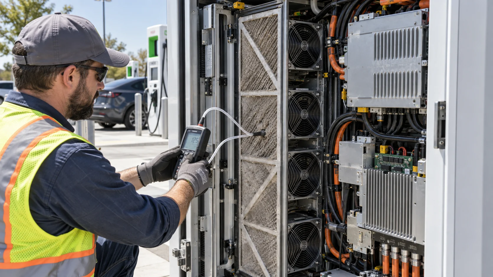
Define clean, service-limit and post-service states. Record differential pressure at the same fan command, filter part number, ambient and power output. If the filter pressure doubles, the fan operating point moves even if the controller holds the same RPM. The module temperature response may show the thermal margin disappearing before the fan alarm appears.
Service access is part of uptime. If the filter cannot be changed without opening the sensitive power bay, maintenance may be postponed until the charger derates. If a fan replacement requires a long outage, N+1 or a controlled shutdown strategy may be more valuable than a nominally higher fan life number.
| State | What to measure | Decision |
|---|---|---|
| Light load | fan current, noise, minimum airflow and module temperature | avoid overcooling and hunting |
| Rated continuous load | heat-sink flow, hotspot temperature and available PWM headroom | confirm full-power operation |
| Peak or repeated sessions | thermal recovery and derating response | confirm service and user performance |
| Loaded filter | pressure, current, temperature and alarm behavior | set maintenance trigger |
| One fan unavailable | remaining flow and controlled power response | confirm redundancy or safe derating |
Noise and Reliability Matter at Public Charging Sites
The fan is heard by customers, neighbors and maintenance staff, and its vibration can affect the cabinet and power electronics.
A high-speed fan may meet a thermal point but create a tonal peak near a parking area. A blade-passing tone can become more noticeable when the cabinet panel, filter frame or heat-sink shroud resonates. Measure at the customer position and at one metre only if that is the project's defined method. Record the fan command and frequency so a tonal issue can be traced to a reproducible operating state.
Bearing selection and temperature affect life. A fan used near a warm heat sink or in a dusty path should be evaluated at the actual temperature and contamination condition, not only at a room-temperature life headline. Vibration mounts, bracket stiffness and cable strain relief should be inspected after thermal cycling and door or service-panel operations.
For a replacement project, compare the current and candidate fans on acoustic spectrum, current, feedback, pressure-flow behavior, mounting and warm restart. A lower purchase price is only useful if the replacement preserves the charger's thermal margin and reduces total service risk.
Acceptance: Link Derating to Evidence, Not One Temperature Number
A robust charger test explains when the system derates, which component triggers it and whether cooling or power conversion is the limiting factor.
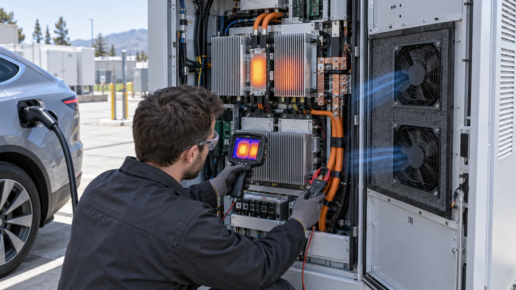
Instrument the critical heat sources: the hottest semiconductor or module base, heat-sink inlet and outlet, magnetics, capacitor bank, cable connection, fan inlet and cabinet exhaust. Log input and output power, ambient, fan command, current, voltage, feedback, pressure and filter state. Repeat after a thermal soak rather than accepting the first five minutes of a cold start.
If the hotspot rises while average exhaust temperature remains acceptable, inspect distribution and thermal interface before selecting a larger fan. If all heat sources rise together and pressure headroom is low, the air path or fan may be limiting. If temperatures are stable but the charger still derates, investigate control thresholds, sensor placement, power-stage limits and communication logic.
The report should state measured values, estimates, supplier limits and the system owner's acceptance criteria separately. That makes a future replacement or customization possible without rewriting the entire thermal argument.
Where MEGA Tech Fits In
We help EV charger teams develop a fan or replacement sample around the real power module, cabinet and control interface.
MEGA Tech can review custom DC axial fans, centrifugal blowers and fan modules for AC chargers, DC fast chargers, power-conversion cabinets, liquid-to-air heat exchangers and charging electronics. The engineering review can cover frame and thickness, pressure-flow behavior, 12/24/48 V rail, PWM or voltage control, FG/RD feedback, connector and harness, bearing choice, IP strategy, temperature range, noise, vibration and redundancy.
For a first review, send charger output and efficiency data, the air-cooled loss share, heat-sink and filter pressure, fan envelope, airflow direction, voltage tolerance, control interface, ambient and solar range, noise point, service condition and expected quantity. A thermal image at the moment of derating is often the fastest way to separate a fan problem from a heat-sink or control problem.
We can also evaluate cost-competitive replacements for Sanyo Denki, SUNON, Delta, NMB or ebm-papst fans. The replacement is judged at the same installed working point and electrical interface, with samples available for small first builds before production quantities are fixed.
Engineer FAQ: EV Fast-Charger Fan Selection
These questions keep power loss, fan pressure and thermal derating in one traceable validation plan.
Q: How much airflow does a 150 kW charger need? A: It depends on efficiency, the air-cooled loss share, allowable temperature rise, altitude, recirculation and the installed pressure. Calculate a planning range, then validate the actual hot spots and heat-sink flow.
Q: Does a fan rated at 300 CFM deliver 300 CFM in the charger? A: Usually not at a restricted pressure. Use the fan P-Q curve and the cabinet system curve at the clean and loaded filter states.
Q: Can PWM solve a charger thermal problem? A: PWM can reduce power and noise or add speed during a load step, but it cannot remove a pressure restriction or a bypass path.
Q: Why can the charger derate with normal fan RPM? A: RPM proves rotor movement, not heat-sink airflow. Check pressure, bypass, fin blockage, sensor position, thermal interface and the actual hotspot.
Q: Is a 48 V fan automatically suitable? A: No. Check the actual voltage range, startup, PWM, FG/RD, current, temperature, IP strategy, bearing and installed pressure.
Q: What should be included in a replacement sample? A: Fan, connector, mounting, airflow direction, pressure-flow behavior, control response, feedback, current, noise, warm restart and clean/loaded filter results.
EV Charger Cooling Review Checklist
Use this checklist before freezing a fan, heat sink, filter or derating curve.
- What is the air-cooled loss at light, rated and peak output?
- Which component is the actual thermal limit?
- What airflow is required at the installed pressure and filter state?
- Where are the pressure taps and critical temperature sensors?
- Does the fan start at the lowest rail voltage after a hot soak?
- Were PWM, FG/RD, current, pressure and temperature time-aligned?
- What happens at a loaded filter, blocked grille or one-fan failure?
- Does the air path bypass the heat sink or recirculate exhaust air?
- Where is acoustic noise measured and which operating state is most audible?
- Which values are measured, estimated or owned by the charger certification team?