Liquid Cooling Does Not Remove Every Fan From an EV Charger
A high-power DC fast charger may use liquid cooling for the densest power modules and still need carefully selected fans for the rest of the cabinet.
A 60–350 kW charger contains more than the power semiconductors that receive the most attention in the thermal design. Power conversion modules, busbars, contactors, control boards, communication hardware, auxiliary supplies, cable assemblies, pumps and the liquid-cooling unit all contribute to the thermal and reliability picture. Liquid cold plates can move heat away from a concentrated SiC or IGBT stack, but they do not automatically cool the control bay, the pump electronics or the heat-rejection side of the loop.
This is why air, liquid and hybrid architectures should be compared as thermal networks rather than labels. Direct air cooling may be effective for a moderate power cabinet in a clean environment. Liquid cooling can reduce local thermal resistance at a high-density module. A hybrid system can use cold plates for the main power path while fans move air through the converter, controls and liquid-to-air heat exchanger. In each case the fan still has an operating point, a pressure path, a control signal and a failure mode.
The design objective is not to put a fan everywhere. It is to identify which heat must be transported by liquid, which heat must be rejected by air, and which air path protects the components that remain outside the cold plate. This guide is a fan and air-side engineering framework; it does not replace charger electrical safety, liquid-loop, insulation, EMC or certification work.
Start With Losses, Not Charger Output Power
The fan is sized from the heat that reaches its air path, not from the headline DC output rating.
Separate conversion losses from delivered charging power. A 150 kW charger may dissipate a few kilowatts under a particular efficiency and load condition, while a 350 kW unit may distribute heat between liquid-cooled modules, air-cooled auxiliaries and the heat-rejection assembly. Obtain loss data at continuous rated output, overload or peak mode, low-voltage/high-current operation and the expected duty cycle.
For an illustrative air-side estimate, assume a converter, control bay and auxiliary section send 1.8 kW into the cabinet air. With a 12 C allowable air rise, density 1.2 kg/m3 and specific heat 1005 J/(kg K), the ideal flow is approximately 1,800/(1.2 x 1005 x 12) x 3600 = 537 m3/h before filter, heat-sink, grille and duct losses. If the air path can only allow an 8 C rise, the screening requirement increases to about 806 m3/h. These are calculations, not product ratings.
For the liquid loop, use the approved coolant flow, inlet temperature, heat capacity and pressure drop. A fan on the liquid-to-air heat exchanger rejects heat from the coolant to ambient air; it does not replace the pump or cold plate. The exchanger fan must be selected at the coil pressure and outdoor condition, while the cabinet fan must be selected from the separate electronics path.
| Zone | Typical evidence | Cooling question |
|---|---|---|
| Power modules | loss versus current, junction/case limit | Does the cold plate keep the device within its limit? |
| Converter and controls | board, capacitor and auxiliary-supply losses | What air flow and pressure does this section need? |
| Liquid-to-air unit | coolant flow, inlet temperature and coil pressure | Can the fan reject loop heat at outdoor conditions? |
| Pump and control hardware | pump power, electronics heat and fault state | Does the loop continue safely if an air fan fails? |
| Cabinet boundary | filter, grille, sealing and solar exposure | Does the installed path protect the remaining air-cooled zones? |
Choose the Architecture From the Thermal Boundary
Air, liquid and hybrid cooling solve different combinations of heat density, contamination, noise and service constraints.
Direct air cooling is attractive when the air-side heat load is moderate, outdoor air can be filtered, and the cabinet can accept the resulting pressure and maintenance. It is simple to diagnose because airflow, temperature, fan feedback and filter pressure can be measured directly. Its boundary is contamination and the fact that it cannot cool below the available ambient heat sink.
Liquid cooling is useful when the power-module heat flux or package density makes a practical air path too large. It adds a pump, hoses, cold plates, quick connectors, coolant monitoring and a heat-rejection interface. The system still needs airflow around components outside the liquid loop and through the radiator or heat exchanger.
Hybrid cooling often provides the most flexible architecture for high-power chargers: liquid removes heat close to the semiconductor, while fans cool controls and reject heat from the liquid loop. The risk is integration. The pump and fan control loops can interact, and a liquid fault can force more heat into the air path. Write the degraded states before selecting the fan.
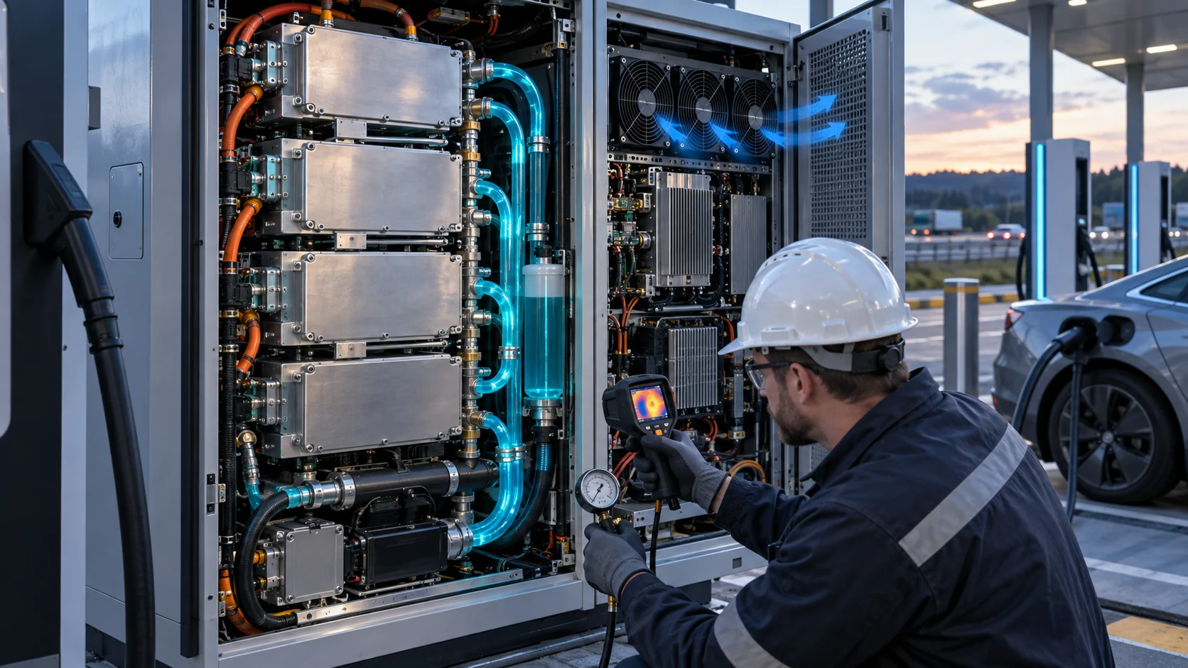
Interactive: Separate Blue Air From Cyan Coolant
The schematic shows why the cabinet fan and the liquid-loop heat-rejection fan should not be treated as one generic cooling requirement.
Use the visual to list the sensors and control loops. The cabinet air loop needs inlet temperature, hotspot temperature, fan command, actual RPM or FG, pressure and filter condition. The liquid loop needs coolant inlet/outlet temperature, flow, pressure, pump state and leak or level protection. The heat-rejection fan needs its own pressure-flow and ambient-temperature validation.
A fan can be spinning normally while the coolant temperature rises because the coil is fouled, the air path is blocked or the fan is operating far left of its P-Q curve. Similarly, the pump can be healthy while the control bay overheats because the auxiliary air fan is undersized or the air bypasses the heat sink. Keep the evidence separate so a fault is not misdiagnosed.
The animation is a qualitative engineering aid, not a CFD result or a guaranteed product performance curve. The final release should use the assembled cabinet, heat exchanger, guards, filters, hoses and control firmware.

Fan Selection for the Cabinet Air Path
The auxiliary air fan often handles the components that still determine charger availability when the main power modules are liquid-cooled.
Map the air path across control boards, auxiliary supplies, contactors, magnetics, busbar supports, capacitor banks and communication electronics. These components may be distributed over a narrow cabinet with cable congestion and multiple heat sinks. The fan must be selected at the installed pressure created by filters, grilles, heat sinks, duct turns and outlet restrictions.
For a worked example, a clean filter contributes 35 Pa, the inlet grille 22 Pa, the internal heat sinks and baffles 68 Pa, the cable path 25 Pa and the outlet 30 Pa. The clean pressure is 180 Pa. If the filter reaches 85 Pa, the service-state pressure is 230 Pa. The correct fan comparison therefore uses the target flow at both 180 and 230 Pa, not a single free-air CFM number.
Specify voltage tolerance, PWM or voltage control, FG/RD or tachometer, startup at low temperature, locked-rotor alarm, bearing life, corrosion exposure, connector and cable exit, acoustic target and service access. A high-static-pressure blower may fit a narrow air path better than a large axial fan, but the decision should follow the pressure-flow curve and the available envelope.
Fan Selection for Liquid-to-Air Heat Rejection
The heat-exchanger fan sees coil pressure, outdoor fouling, high ambient and often a different control profile from the cabinet fan.
Obtain the heat exchanger pressure drop at the required air flow and account for rain hood, guards, louvers, filters and fouling allowance. A finned coil can show a modest clean pressure and a much higher service pressure after dust or salt accumulation. The fan should have enough margin to reject heat at the hottest approved ambient without running continuously at its limit.
For an illustrative 4 kW liquid-to-air heat rejection path with a 15 C air-side rise, the ideal air volume is approximately 4,000/(1.2 x 1005 x 15) x 3600 = 796 m3/h. If the exchanger requires 260 Pa at that flow and the outdoor hood/filter adds 70 Pa, the fan must be checked near 330 Pa, not at zero pressure. The coolant side still needs its own flow and pressure validation.
Check the fan's high-ambient motor and electronics limits, restart behavior, condensation, salt exposure, vibration, noise and fault feedback. If the fan is installed near a public charging bay, measure tonal behavior at the user position. A controller that ramps the fan during a charge session should avoid hunting and should distinguish a dirty coil from a fan failure.
Thermal Derating Is a Control Decision, Not Only a Hardware Failure
The charger should know whether it is losing margin because of ambient temperature, coolant flow, fan pressure, filter loading or a component fault.
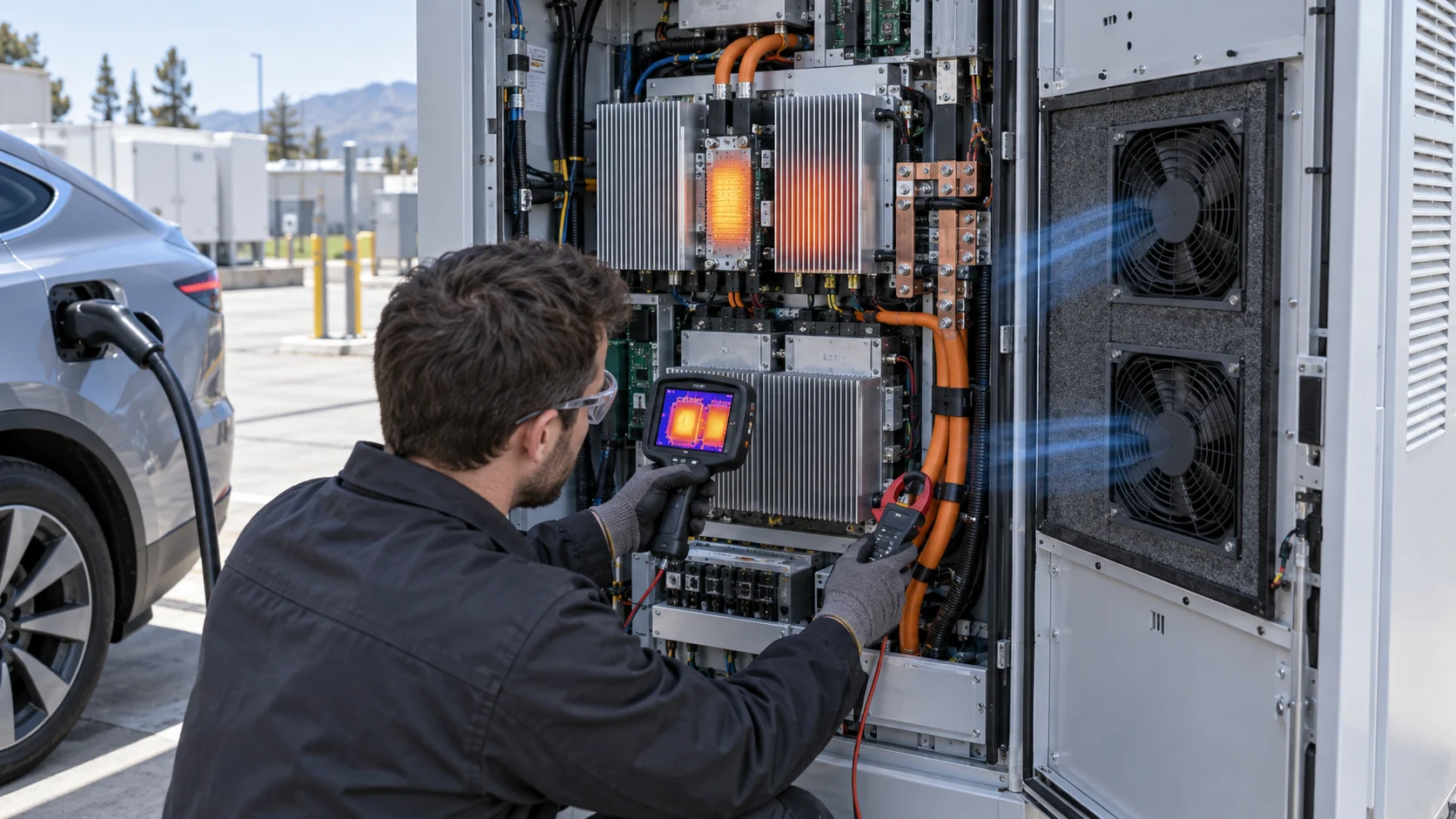
Record charge power, DC current, module temperature, coolant temperature, cabinet inlet temperature, fan command, actual RPM, pressure and ambient conditions together. A charger may derate because a power module is hot, but the cause may be a blocked air path or a heat-rejection fan that is rotating at normal speed without delivering the required flow.
A useful control sequence can use feed-forward from requested charge power and ambient temperature, then trim from the limiting component or coolant temperature. Add hysteresis so the fan does not cycle around a threshold. Validate the minimum stable duty, startup, maximum command, fault delay and recovery after the load drops. If the fan reaches maximum command and temperature still rises, the charger should make the derating step explicit instead of waiting for an uncontrolled shutdown.
For an illustrative fan-energy estimate, three 48 V fans drawing 0.35 A each use about 50.4 W at full command. If they operate at 45% of that input for six hours and full input for two hours during a daily operating window, the idealized energy is about 50.4 x (0.45 x 6 + 2) = 236 Wh. The estimate excludes controller losses and does not justify a control curve without thermal validation, but it shows why variable-speed operation can matter at a charging site.
Noise, Dust and Serviceability Still Matter at a Public Charger
A technically adequate cooling system can still create field problems if it is loud, difficult to clean or impossible to diagnose without opening a live cabinet.
Fast chargers often sit near homes, retail entrances, fleet depots and parking areas. Measure sound pressure at the user position and include high-speed charging, hot ambient and fan recovery. Check narrowband blade-pass tones as well as A-weighted average noise. A larger fan at lower speed may help, but only if the cabinet opening and pressure curve support it.
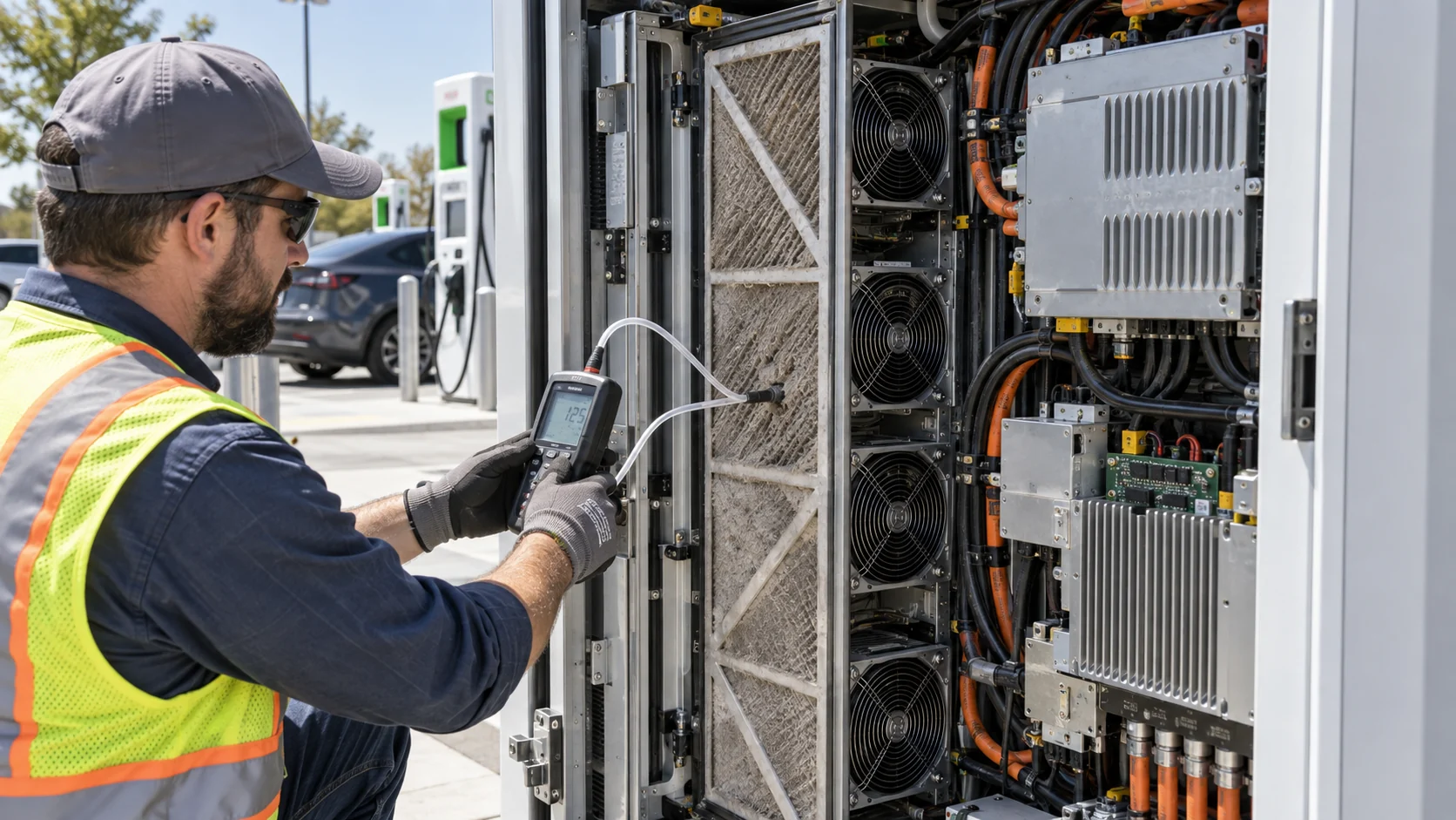
Direct-air paths need a filter strategy that balances efficiency and pressure drop. Specify the clean pressure, service threshold, replacement access and the consequence of a missing or incorrectly installed filter. Salt, dust and fibres can foul both the cabinet filter and the heat-exchanger coil. The maintenance plan should use differential pressure and temperature evidence rather than a visual check alone.
For outdoor units, verify rain paths, drainage, condensation, cable glands, corrosion and connector sealing. A fan's component rating does not certify the modified cabinet. If the charger uses a separate liquid loop, also define leak detection, quick-disconnect inspection and the fan fallback if the liquid system is unavailable.
An Anonymous Customer Example: Hybrid Cooling for a Fleet Charger
An integrator developing a high-power fleet charger used liquid cooling for the main conversion stack but still saw a control-bay temperature rise during repeated sessions.
The initial design sized the liquid loop from the power-module loss and treated the remaining cabinet air as a low-load section. During a sequence of back-to-back charging sessions, the liquid temperatures stayed within their expected range, but the auxiliary supply and control-board area accumulated heat. The cabinet fan was running, yet the air path had a restrictive filter, a narrow heat-sink passage and a cable bundle that redirected flow around the hottest zone.
MEGA Tech reviewed the air-side heat balance, fan command, filter pressure, heat-sink resistance, cable routing, ambient temperature and liquid-to-air unit interface. A custom fan sample with a revised pressure-flow point and the required feedback signal was compared in the populated cabinet. The control curve was then checked during normal charging, peak charging and a loaded-filter condition.
The customer retained the liquid loop for the dense power modules and revised the auxiliary air path rather than increasing pump capacity to solve an air-side problem. The final test record separated coolant temperature, cabinet hotspot temperature, fan RPM, pressure and charge power. That made the derating response easier to diagnose and gave procurement a measurable fan requirement.
This is an anonymized engineering scenario, not a published customer performance claim. The transferable lesson is that hybrid cooling needs two linked but independent validation plans: liquid-loop evidence for the cold plate, and fan/air-path evidence for everything outside it.
| State | Measure | Decision |
|---|---|---|
| Normal charging | charge power, coolant and cabinet hotspot | establish both operating points |
| Peak charging | module loss, fan command, coolant flow and air temperature | check coupled thermal margin |
| Loaded filter / coil | air-side DP, flow, fan current and hotspot | define service-state margin |
| Pump or fan fault | alarm, fallback and derating response | confirm controlled protection |
| Hot ambient | inlet, skin, coolant and exhaust temperatures | verify field thermal boundary |
Where MEGA Tech Fits In
We help EV-charger OEMs develop the fan interface for cabinet air cooling, liquid-to-air heat rejection and hybrid systems.
MEGA Tech can review custom DC or EC axial fans, compact blowers and fan modules for EV charger control bays, power-conversion enclosures, heat-exchanger coils, charging cabinets and auxiliary electronics. The engineering review can include P-Q behavior, coil and filter pressure, 12/24/48 V operation, PWM or voltage control, FG/RD feedback, startup, bearing selection, outdoor protection, corrosion exposure, noise, connector position and small-batch samples validated on the customer's assembly.
For a first review, provide charger power, measured or estimated losses by zone, air and liquid paths, target airflow at static pressure, heat-exchanger data, ambient and altitude, voltage tolerance, control interface, feedback, noise target, filter condition, quantity and failure strategy. A current fan part number is useful for replacement work, but outline dimensions alone do not prove equivalent thermal performance.
We also support cost-competitive replacement fans for Sanyo Denki, SUNON, Delta, NMB and ebm-papst when the replacement is checked at the same installed pressure, mounting, voltage, feedback, acoustic and environmental condition. Our scope is the custom fan and air-side interface; the charger power stage, cold plate, pump, coolant and safety certification remain system responsibilities.
Engineer FAQ: Fans in Hybrid EV-Charger Cooling
These questions help engineering and procurement teams define the fan requirement without confusing liquid-loop and air-side responsibilities.
Q: If the power modules are liquid-cooled, why do I still need fans? A: Control boards, auxiliary supplies, contactors, magnetics, pumps and the liquid-to-air heat exchanger may still require forced air.
Q: Should the cabinet fan and heat-exchanger fan use the same P-Q requirement? A: No. They see different air paths, pressure drops, heat loads and control states.
Q: Can a stronger fan replace a larger liquid loop? A: Not automatically. The fan can only reject heat that reaches the air-side heat exchanger or cabinet path; the cold plate and coolant flow still set the liquid-side limit.
Q: How do I calculate a first airflow estimate? A: Use Q = W/(rho x cp x delta T) for the relevant air-side heat, then select and test the fan at the installed pressure.
Q: What causes charger derating even when the fan RPM looks normal? A: Filter or coil pressure, bypass, poor distribution, high ambient, sensor placement and reduced fan performance can all coexist with normal RPM.
Q: What data should I send for a custom 48 V fan review? A: Send airflow at pressure, fan size, voltage range, PWM/FG/RD interface, noise target, filter/coil data, ambient, altitude, quantity and fault strategy.
Q: Can MEGA Tech support prototype and replacement fan work? A: Yes. We can adjust the fan interface, build samples and support air-side pressure, thermal, noise, feedback and environmental validation before production.
EV-Charger Hybrid Cooling Review Checklist
Use this checklist before freezing the cabinet fan, heat-exchanger fan, control curve or liquid/air architecture.
- Were charger losses separated into liquid-cooled power modules, cabinet air and heat-rejection paths?
- Was the fan selected from airflow at the installed pressure rather than free-air CFM?
- Were clean and service-state filter or coil pressure measured?
- Were cabinet hotspot, coolant inlet/outlet, charge power and ambient recorded together?
- Were fan and pump control loops validated independently and as a hybrid system?
- Were PWM/EC minimum duty, startup, FG/RD feedback, locked-rotor and restart tested?
- Was the heat-exchanger fan checked at high ambient and fouled-coil conditions?
- Were public-position noise, tonal peaks and fan speed hunting checked?
- Were fan, pump, sensor, filter and coolant faults tested with a controlled derating response?
- Are measured values, estimates, supplier curves and certification limits clearly separated?