A Thermal-Derating Alarm Is a Symptom, Not a Diagnosis
When a DC fast charger reduces output power, the cause may be a hot power module, a blocked filter, a weak fan, recirculation or a control decision that arrived too late.
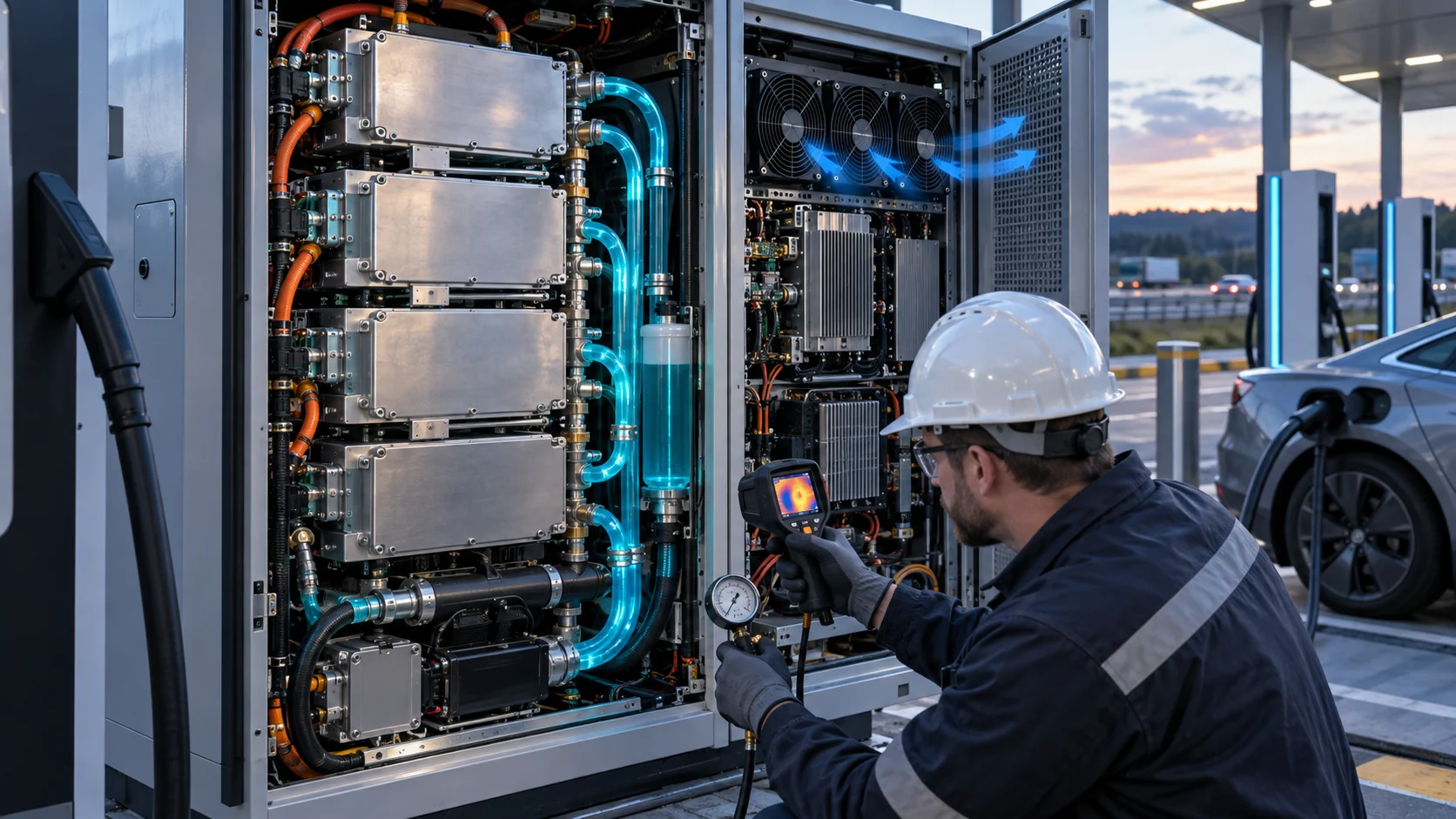
EV fast chargers operate with dense power electronics, high current, repeated sessions and outdoor exposure. Their cooling system may combine cabinet fans, heat sinks, a liquid loop, a heat exchanger, filters and control electronics. A charger can therefore display a thermal warning while every fan appears to be rotating. Rotation alone does not show that the fan is delivering the required airflow at the installed pressure.
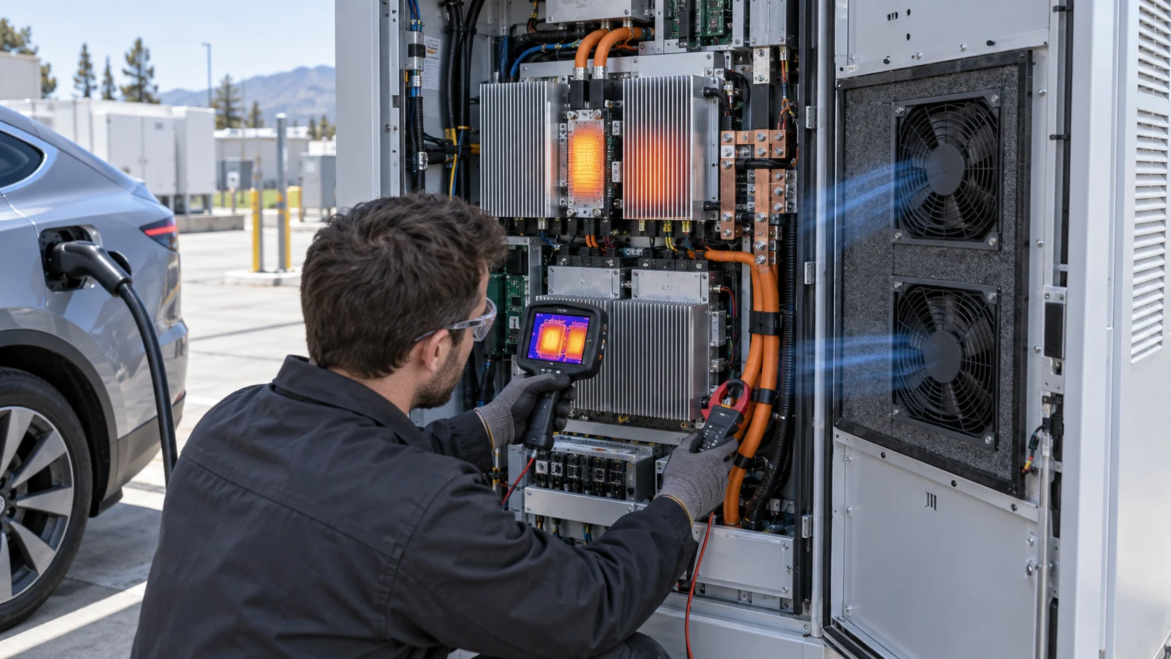
The engineering task is to connect delivered charging power with the thermal path that limits it. Record requested and delivered power, rectifier or power-module temperature, inlet and exhaust temperature, ambient condition, filter or coil differential pressure, fan command, actual RPM, current and diagnostic code on the same time axis. Without that correlation, a team can replace a fan when the real problem is a dirty coil, a recirculation path or a sensor location that misses the hotspot.
This article provides a practical fan and air-path diagnostic method. The calculations are screening examples, not a product guarantee. The charger owner remains responsible for electrical safety, insulation, EMC, liquid cooling, fire protection and certification; MEGA Tech supports the custom fan and air-side interface.
Separate Charger Heat From Vehicle-Side Battery Limits
A lower charging power does not automatically mean the charger cabinet is too hot, so the first test must separate charger-side and vehicle-side limitations.
A vehicle may reduce current because of battery temperature, state of charge, cell balancing or a vehicle control request. The charger may also reduce power because its rectifier, DC bus, magnetics, cable, connector or cabinet electronics approach a limit. The same displayed power can therefore come from different thermal boundaries. The test record should preserve the vehicle, SOC, requested power, delivered power and charger temperatures together.
Use a reference vehicle or an electronic load where possible to produce a repeatable charger-side test. Repeat the same power profile with a clean filter, service-limit filter and controlled ambient. If the charger derates at the same cabinet temperature and pressure regardless of vehicle, the cabinet path deserves priority. If it changes with the vehicle request but cabinet temperatures remain stable, the fan may not be the limiting component.
This distinction matters for procurement. A replacement fan cannot solve a battery-side current limit, and a larger fan cannot replace a liquid-loop or connector redesign. It can, however, restore the air-side operating point when filter pressure, heat-sink resistance or fan performance has moved outside the original design margin.
Build a Heat-Loss and Airflow Estimate
A first estimate turns charger efficiency into a measurable airflow target and shows why a free-air CFM number is insufficient.
Consider an illustrative 60 kW air-cooled charger operating at 96.5 percent efficiency. The conversion loss is approximately 60,000 x (1 - 0.965) = 2,100 W. If 1,500 W reaches the cabinet air path and the rest is removed through another interface, an air-side estimate can use the 1,500 W value. With an allowed average air rise of 15 K and air heat capacity of about 1,200 J/(m3 K), Q = 1,500/(1,200 x 15) = 0.0833 m3/s, or about 176 CFM.
This is a screening value. The hottest device may require a lower local rise, the air may bypass the heat sink and solar radiation may add another load. If a 300 W solar gain is included, the same calculation becomes 1,800/(1,200 x 15) = 0.10 m3/s, or roughly 212 CFM. The final selection must use measured component temperatures and the installed pressure-flow point.
Suppose the filter, louvre, heat sink, cable path and outlet require 220 Pa at the target flow. The fan must deliver approximately 176 to 212 CFM at 220 Pa and at the service-limit pressure. A fan rated at 220 CFM in free air may be inadequate. A pressure-flow curve and a populated-cabinet measurement are the minimum evidence needed before locking the BOM.
| Input | Example | Use in the review |
|---|---|---|
| Charger efficiency | 96.5% | Converts electrical power to loss estimate |
| Air-side heat | 1,500 W | Separate from liquid or connector heat |
| Solar allowance | 300 W estimate | Check outdoor cabinet condition |
| Allowable average rise | 15 K | Screens 176 to 212 CFM |
| Installed pressure | 220 Pa plus fouling | Select the fan on the loaded P-Q curve |
Animated Model: Clean Filter, Loaded Filter and Fan Saturation
The same fan command can stop protecting the power module when the filter and heat exchanger consume the available pressure head.
In a clean state, blue particles move through the inlet, heat sink and exhaust with a reasonable margin. As the filter loads, amber restriction markers grow and the operating point moves toward lower airflow. The controller may respond by increasing speed, but a fan eventually reaches its maximum command. At that point, the charger can continue to show normal RPM while the actual cooling capacity is no longer sufficient.
The animated schematic is qualitative. It is not a CFD result or a universal pressure multiplier. Its purpose is to make the commissioning sequence clear: measure clean state, measure service-limit state, then identify the alarm point before the fan saturates or the power module derates.
If the charger uses a heat exchanger, repeat the same test on both air circuits. A clean internal circuit can still fail if the external coil is fouled. Conversely, a high internal fan speed cannot fix a blocked external path. Name each pressure measurement and each fan in the test record so a replacement supplier receives the real duty.

How to Tell a Fan Problem From a Filter or Coil Problem
A structured pressure and temperature comparison is faster than changing parts one at a time in the field.
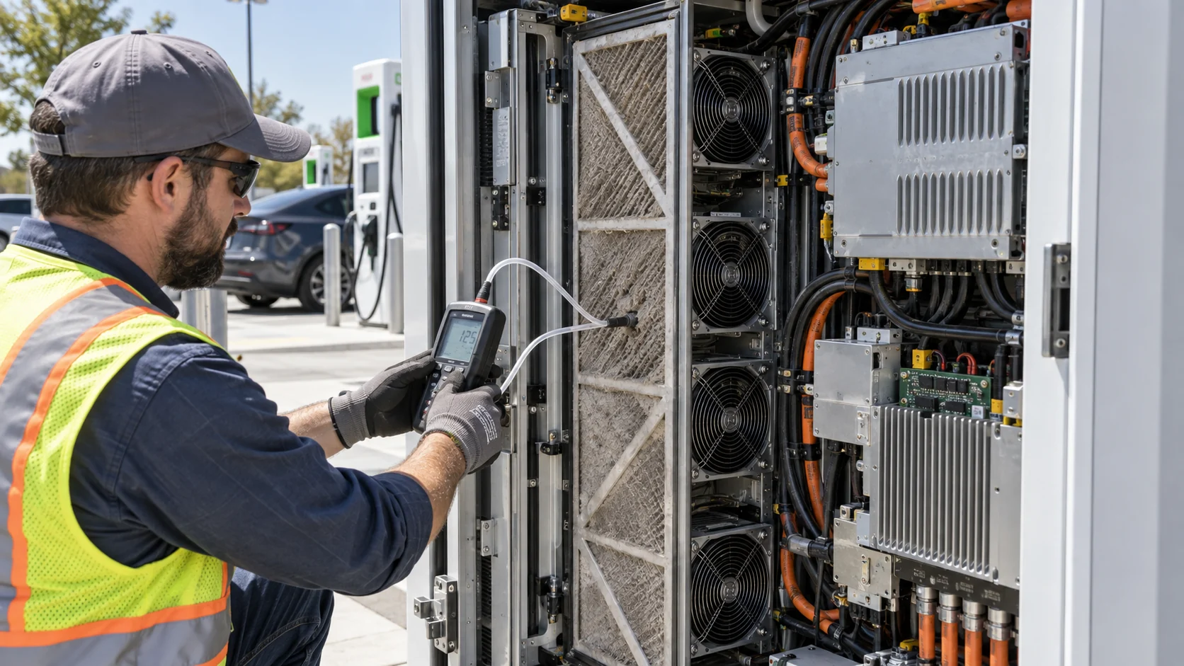
Start with fan electrical evidence: supply voltage at the connector, current, command, actual RPM and fault feedback. Then measure differential pressure across the filter, heat exchanger or heat sink path. If the fan current and RPM are normal but differential pressure is high and flow is low, the restriction deserves attention. If pressure is normal but the fan cannot reach its expected flow or current, check rotation, blade damage, bearing condition, wiring and the fan curve.
Compare inlet, outlet and component temperatures. A small inlet-to-outlet rise with a hot local device may indicate bypass or poor heat-sink contact. A high outlet temperature with acceptable component temperatures may be normal heat rejection. A rising inlet temperature can indicate exhaust recirculation, especially with a wall, service door or neighboring charger close to the exhaust.
Preserve the removed filter, fan or seal when investigating a field failure. Record the date, site condition, session power, ambient, pressure, images and alarm history. This gives procurement and design teams evidence for a revised fan, filter service interval or cabinet geometry instead of a guess based on one noisy measurement.
| Observation | Likely direction | Next measurement |
|---|---|---|
| Normal RPM, high pressure, low flow | Filter/coil or path restriction | Differential pressure and service condition |
| Low RPM, normal pressure | Fan command, voltage or fan fault | Connector voltage, current and FG/RD |
| Normal flow, hot local device | Bypass or heat-sink interface | Surface map and flow distribution |
| Hot inlet, normal exhaust | Recirculation or solar load | Inlet position, exhaust clearance and sun condition |
| Derating follows vehicle only | Vehicle-side battery limit | Vehicle request and charger temperature correlation |
High Ambient Turns a Small Margin Into a Charging Delay
A hot site can reduce the available thermal headroom before the charger begins a session, making the same fan and filter condition much less forgiving.
At 40°C ambient, a charger with a 55°C rectifier limit has only 15 K of air-temperature margin before local temperature rise, contact resistance, sensor error and recirculation are considered. If the inlet is actually 45°C because of solar-heated panels or exhaust return, the nominal margin falls to 10 K. The exact limit is product-specific, but the method is general: measure the air at the power module path, not only the weather station value.
A field test should repeat the charging profile at moderate and high ambient, with the same vehicle or load, filter condition and fan control. Record the time to derating and the delivered power after derating. Public research on hot-climate DC fast charging has shown that charger-side thermal conditions can materially reduce offered power and extend charging time; the engineering response is to validate the cooling path rather than assume the vehicle is always the cause.
The fan selection should retain a speed or pressure margin for heat, dust and aging. If the fan reaches maximum command at the start of summer, there is no control headroom left for the service interval. A larger fan, better pressure path, alternate filter or heat-exchanger redesign may be needed before adding more aggressive firmware.
Noise, Fan Arrays and N+1 Claims
A public charger needs cooling capacity without creating avoidable tonal noise, and a fan array needs proof after one module is unavailable.
Fast chargers may be installed near homes, shops or fleet depots. Measure sound at the user position during startup, steady high-power charging, thermal recovery and a loaded-filter state. Listen for blade-pass or motor tones, not only the A-weighted average. A larger fan at moderate speed can help, but only if the air path and pressure curve allow it to deliver the required flow.
For an array, calculate the duty with all fans operating and with one fan stopped. The remaining fans may see a different system resistance, while the failed module may create reverse-flow resistance. Do not assume N+1 means the same airflow minus one fan. Measure the hot spot, flow distribution, pressure, current and derating response after the failure.
The control system should also avoid hunting. A narrow temperature threshold can make the array ramp repeatedly during partial-load sessions. Use hysteresis, stable speed states and a defined response to fan feedback and filter pressure. The accepted result is the combination of delivered power, temperature, noise and fault behavior.
Maintenance Thresholds Should Arrive Before Derating
A service alarm is useful only when it gives the operator time to act before the charger loses power or overheats.
Set the threshold from measured evidence: filter differential pressure, heat-exchanger pressure, fan command saturation, component temperature and delivered power. If the filter alarm is triggered only after maximum fan command, it is not a preventive threshold. If it is too early, service cost and unnecessary truck rolls increase. The correct point is cabinet-specific and should be tested with the intended filter media and airflow.
Use a trend where possible. A gradual rise in pressure at the same fan command can identify fouling before a thermal alarm. A sudden rise may indicate a collapsed filter, blocked louvre or door-seal problem. Combine the trend with fan feedback, ambient and charging power so the service system does not confuse a low-load session with a healthy high-load path.
Maintenance also needs a physical procedure. Record whether the filter can be replaced without exposing hazardous parts, whether the fan connector is accessible, whether the gasket must be replaced and whether the cleaning method can damage the media or fan. A reliable thermal design includes the technician's real service sequence.
An Anonymized Fast-Charger Field-Diagnosis Example
A useful case record follows the data trail from a power alarm to the installed fan and filter condition.
In an anonymized outdoor fast-charger deployment, several units reduced power during hot afternoon sessions. The first service report noted that the fans were rotating and the filters looked only moderately dirty. A time-aligned review showed that the inlet temperature rose with solar exposure, the filter differential pressure increased during the session and the fan command approached its maximum before the rectifier temperature crossed the derating threshold.
The team repeated the profile with a clean filter, the original service-state filter and a controlled inlet temperature. The pressure-flow result showed that the installed fan had little headroom at the service-state pressure. A custom high-static-pressure fan sample and a revised filter path were then tested at the same voltage, mounting and controller interface. The test included noise at the public position and a fan-feedback fault.
The customer retained the charger power stage and changed the maintenance threshold and air-side margin rather than treating every power alarm as a vehicle problem. The final record separated measured results from estimates and confirmed the derating response under high ambient. This is an anonymized engineering scenario, not a named customer result or a universal fan-performance claim.
How MEGA Tech Supports EV-Charger Fan Validation
MEGA Tech helps charger OEMs turn a thermal alarm into a measurable fan and air-path requirement.
We can review custom DC or EC axial fans, compact centrifugal blowers and fan arrays for power-module cabinets, heat sinks, filters, heat exchangers and auxiliary electronics. The review can include pressure-flow behavior, 12/24/48 V operation, PWM or voltage control, FG/RD feedback, startup, bearing selection, acoustic target, outdoor construction, cable exit, connector position and small-batch samples tested on the customer's populated charger.
For a first review, send charger power, loss by zone, requested and delivered power traces, target airflow at static pressure, filter and coil pressure, ambient and solar condition, fan envelope, voltage tolerance, control interface, feedback, noise target, maintenance state, quantity and fault strategy. A current fan part number helps replacement work, but outline dimensions, RPM or free-air CFM alone do not prove equivalence.
Our boundary is clear: MEGA Tech does not certify the complete charger, vehicle, battery, liquid loop, connector, EMC, insulation or fire system. We support the fan and air-side interface, provide engineering samples and help the customer validate the installed operating point and failure response.
Recommended Fan Starting Points
These catalogue series may be suitable starting points for this application. Final selection depends on the installed airflow, static pressure, voltage, noise target and operating environment.
Request a sample for validation on your equipment.
Engineer FAQ: EV Fast-Charger Fan and Filter Diagnosis
Use these questions during field troubleshooting, supplier comparison or charger design review.
Q: Does a thermal-derating alarm prove the fan is too small? A: No. The cause may be a filter, heat exchanger, bypass, recirculation path, sensor location, liquid loop or vehicle-side limit.
Q: Does normal fan RPM prove normal airflow? A: No. Measure pressure and flow at the installed path. A loaded filter can move the operating point while RPM remains normal.
Q: How should I estimate the first airflow? A: Use Q = W/(rho x cp x delta T) for the relevant air-side loss, then select and test the fan at the installed pressure.
Q: How early should a filter alarm occur? A: Before fan command saturation or component temperature derating, based on clean and service-limit pressure tests.
Q: Do two fans automatically give twice the airflow? A: No. The combined P-Q curve and system resistance must be tested, including one-fan-off reverse resistance.
Q: What should be measured during a field session? A: Requested/delivered power, vehicle request, ambient, inlet/outlet, component temperature, pressure, fan command, RPM, current and alarms on one time axis.
Q: Can MEGA Tech replace a branded charger fan? A: We can evaluate a cost-competitive replacement, but equivalence must be proven at the same pressure, mounting, voltage, feedback, noise and environmental condition.
Q: Can a stronger fan remove the need for a liquid loop? A: Not automatically. The fan can only remove heat that reaches the air-side path or heat exchanger.
EV Fast-Charger Cooling Design Review Checklist
Use this checklist before changing a fan, setting a service alarm or releasing a high-power charger cabinet.
- Were vehicle-side current limits separated from charger-side thermal limits?
- Were heat losses separated into power module, cabinet air, liquid loop and connector zones?
- Was the fan selected at the installed pressure, clean condition and service-limit condition?
- Were inlet, exhaust, heat-sink, filter and heat-exchanger paths checked for bypass and recirculation?
- Were high ambient and solar-heated inlet conditions tested with the real cabinet?
- Were fan command, actual RPM, voltage, current, FG/RD and differential pressure recorded together?
- Was the filter alarm set before maximum fan command and thermal derating?
- Was one fan stopped in an N+1 array and the remaining airflow measured?
- Were public-position noise, tonal peaks and speed hunting tested?
- Are measured data, estimates, supplier curves and charger certification limits clearly separated?