
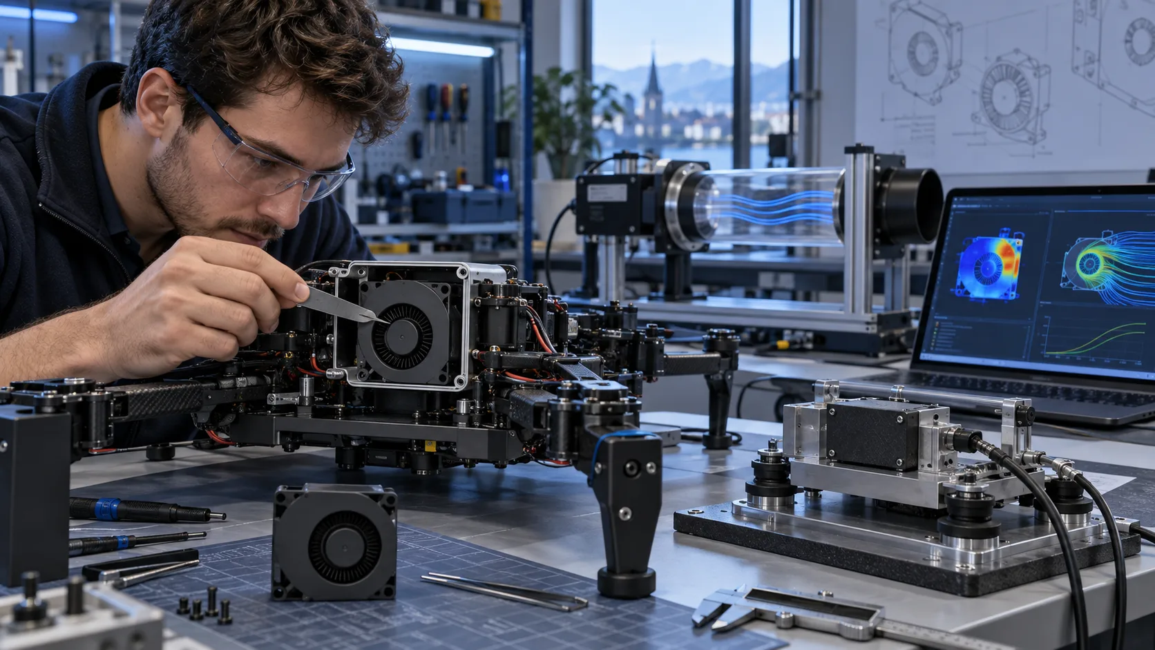
The thermal problem starts before the first production order
For a startup hardware team, the first fan is not a purchasing decision. It is part of the product architecture.
A new drone, robot, projector or energy-storage product rarely begins with a complete thermal specification. The enclosure is changing, the available fan space is uncertain, and the first prototype may only exist in a handful of units. A catalogue fan can appear to fit while its airflow path, vibration response, noise or connector does not.
That is why early cooling work should begin with the product constraint: heat load, available volume, voltage, airflow direction, pressure resistance, noise limit, control signal, environment and expected production path. The fan model comes after those constraints, not before them.
The cost asymmetry explains the discipline. A fan decision revisited at the sample stage costs a drawing revision. The same decision revisited after tooling, certification or a pilot build costs mould changes, retest time and slipped launch dates. Early-stage teams do not have more engineering time than large companies - they have less slack when a cooling assumption fails late.
For a startup, the practical goal is not to over-design the first sample. It is to create a testable cooling path quickly, learn from the populated prototype and keep the approved design transferable to a small batch or later production run.
- Start with the product constraint, not a preferred fan catalogue
- Treat the first sample as a thermal learning tool
- Test the fan inside the populated prototype
- Keep the approved configuration compatible with a repeatable build
What a cooling supplier needs from an early-stage team
A perfect drawing is not required, but the engineering question must be concrete enough to test.
A useful first request can be built from a sketch, enclosure photos and a short requirement table. The key inputs are heat sources and estimated heat load, available fan envelope, inlet and outlet locations, voltage, control method, target airflow or pressure, noise limit, operating temperature, vibration or shock exposure and the expected sample quantity.
If some values are not known, label them as assumptions. A supplier can help convert them into a test plan, but an assumed heat load should not silently become a guaranteed thermal result. The same applies to free-air CFM: it is a starting value until the installed resistance is known.
Writing the unknowns down also protects the schedule. A requirement table that separates measured values from assumptions lets the team order long-lead items in parallel with testing instead of waiting for every number to be confirmed first.
This early exchange is especially useful for startups because it prevents the sample from becoming a dead-end part that fits one prototype but cannot be controlled, tested or sourced consistently later.
- Heat load and component temperature target
- Fan envelope, mounting holes and cable route
- Voltage, PWM, tachometer, FG or other interface
- Airflow direction, pressure resistance and acoustic target
- Environment, vibration, service access and sample quantity
An anonymised drone customer: noise during movement
The customer did not need a catalogue replacement. It needed a compact blower that stayed quiet when the product moved.
An anonymised drone-equipment customer used a 45×45×10 mm centrifugal blower. The blower was acceptable at rest but produced abnormal noise during movement and vibration. The investigation found a small impeller overhang beyond the housing that created an intermittent contact risk with surrounding parts.
The problem was not solved by simply changing the motor speed. The mechanical clearance, vibration direction, mounting support, cable routing, outlet restriction and installed airflow path all had to be reviewed together. The customer's electrical interface and cooling requirement also had to remain compatible with the prototype.
The comparison below shows the two sample configurations side by side: where the impeller rim sits relative to the frame wall, and what that difference does under movement.
MEGA Tech developed a revised sample with the impeller fully enclosed inside the frame. The published project case reports no abnormal noise or contact in the redesigned configuration, while retaining the original electrical and application requirements. The result is specific to that project, but the design method applies to other compact moving products.

- Application: compact drone equipment
- Product format: 45×45×10 mm centrifugal blower
- Observed issue: abnormal noise under movement and vibration
- Design response: enclosed impeller and controlled clearance
- Validation focus: no contact, with electrical and airflow requirements retained
Prototype testing should reproduce the failure mode
A quiet fan on a test stand does not prove a quiet fan inside a moving product.
The test fixture should reproduce the conditions that created the problem. For a drone or robot, that can include mounting orientation, bracket stiffness, vibration direction, shock or tilt, nearby walls, outlet transitions and cable loading. For a projector or industrial device, it may include the real grille, filter, heat sink and enclosure cover.
Measure more than one number. Record voltage at the fan connector, speed, current, airflow or pressure at the installed condition, acoustic level, component temperature and any abnormal vibration or contact. If the issue is intermittent, record the operating state and fixture condition when it occurs.
Turn the failure mode into an explicit acceptance test with a limit: the noise signature that counts, the contact that must not occur, the temperature that must hold. An acceptance test written after the result is known is a description, not a limit.
This approach follows a broader prototype-validation principle: instrument the prototype so the result can validate the model and guide the next design iteration. It also prevents a startup from spending several prototype cycles changing the wrong component.
- Reproduce the product mounting and vibration direction
- Measure the installed airflow path, not only free-air performance
- Record voltage, speed, current, noise and temperature together
- Repeat the test across representative samples
- Turn the failure mode into an explicit acceptance test
What each validation stage must prove
Sample, pilot and production builds answer different questions, and the fan evidence should match the stage.
Industry practice splits the path to production into three validation stages. Engineering validation test (EVT) works with tens of units and asks whether the core design - including the cooling concept - meets its function and performance targets. Design validation test (DVT) works with dozens to hundreds of near-final units and asks whether the design survives real conditions: vibration, thermal cycling, certification work. Production validation test (PVT) is a pilot run on the intended line and asks whether the factory can build the product repeatedly at the required quality.
The fan evidence should grow with each stage. A sample that passed one installed airflow measurement is not the same as a design that survived vibration and thermal cycling on the mounted fan, and neither is the same as a line that can screen incoming fan lots by speed, current and noise.
Skipping a stage does not save the time; it moves the cost to a later stage where changes are slower and more expensive. The table below states what the fan evidence must show at each stage.
| Stage | Typical build size | Question for the fan | Fan evidence to record |
|---|---|---|---|
| EVT | Tens of units | Does the cooling concept work at the operating point? | Installed airflow and pressure at the real inlet, temperature rise on the named critical parts |
| DVT | Dozens to hundreds of near-final units | Does the design survive transport, vibration and environment? | Vibration and shock on the mounted fan, thermal cycling, noise spectrum, PWM and tach behavior at voltage limits |
| PVT | Pilot run on the production line | Can the line build it repeatedly? | Incoming inspection limits for speed and current, sampling plan, traceability of fan lots to test results |
Acceptance numbers for a fan sample
A sample review goes faster when every requirement is written as a number with a test condition.
The operating point comes first. If the product needs 40 CFM at 130 Pa of installed resistance, the system constant is 130 divided by 40 squared, or about 0.081. Any candidate fan curve can be checked against that parabola before a sample is ordered - and the sample test should confirm the installed flow, not the free-air value on the box.
Control and feedback limits come next. A 4-wire fan takes a PWM control signal in the 21 to 28 kHz range with 25 kHz nominal and reports 2 tach pulses per revolution (Intel 4-wire fan specification). Write the commanded duty range, the minimum start command and the expected tach reading at each test condition into the sample plan, then confirm them at the lowest and highest supply voltage.
Noise and life close the list. An acoustic limit is only testable with a distance, an orientation and an operating state - for example dBA at 1 metre in the direction the user hears. A life expectation needs a bearing type, a speed and a temperature at the fan; at equal conditions the fan that runs cooler lives longer, and every 15 K reduction roughly doubles expected life (IPC-9591 guidance).
- Installed airflow and pressure with the test fixture named
- Duty range, start command and tach reading at voltage limits
- Noise limit with distance, orientation and operating state
- Life assumption with bearing type, speed and temperature
- Current limit at nominal and stall conditions
Freeze the interface before the pilot build
Small volume does not mean the specification should remain informal.
Once the sample works, freeze the details that made it work: fan model or custom variant, frame and thickness, voltage, connector and pinout, cable length and exit direction, PWM frequency range and tach configuration, airflow direction, bearing choice, clearance limits, mounting holes and screw torque. If the fan is going into a small pilot build, define the same test points used during validation.
The freeze lives in an interface record: one drawing revision plus the acceptance test sheet. It should state, for every parameter, whether the value is a catalogue value or an installed acceptance value measured in the product. Mixing the two is how a passing sample turns into a failing pilot build.
This is where an engineering supplier can help a startup move faster. The first build may require only a few samples, but the fan should still be developed with production intent so a successful prototype does not become unavailable or inconsistent when the product gains traction.
- Freeze the mechanical and electrical interface
- Document the operating point and test fixture
- Define inspection points for clearance, speed and electrical performance
- Keep sample, pilot and production versions traceable
- Review cost reduction only after the thermal requirement is stable
Change control after the sample passes
A validated configuration is an agreement, and every change to it needs evidence.
After the sample passes, pressure comes from two directions: the team wants cost or lead-time improvements, and the supply chain proposes alternate parts. Both are legitimate - if they go through review. A change in motor, bearing, grease, impeller material, driven electronics, connector or assembly process can move airflow, noise, startup behavior, life or EMC, and the movement is not always visible in a data-sheet comparison.
Formal standards treat this seriously. DIN EN 12101-3, Annex B classifies bearing type, lubricant and impeller material as critical component changes: replacing them calls for new tests on the affected frame sizes, because thermally and mechanically the altered part is treated as a new configuration. The same logic applies to a compact DC blower, whatever the product standard is.
A workable rule for a small team: every change gets a one-page note that records what changed, which evidence is needed and which of the existing tests must repeat. The note costs an hour; skipping it can cost a validation cycle.
If the fan becomes unavailable, the same discipline applies to the replacement: match the installed operating point, interface and mounting, then repeat the installed acceptance test before the pilot build uses it.
From sample quantity to a controlled small batch
The handoff from validation to pilot is a document set, not a handshake.
The controlled handoff should include a drawing or interface record, inspection points, functional test limits and a clear distinction between catalogue values and installed acceptance values. Each pilot unit should be traceable to a fan lot, so a field question later can be answered by configuration instead of by memory.
Sample quantity deserves the same honesty. The right number is enough to test the main configuration and repeat the critical result - one to prove, one to repeat, one to keep as a reference against later lots. Presenting a supplier minimum as an engineering requirement, or the reverse, only hides the real constraint.
When the pilot build runs on the intended line, the fan joins the production test flow: incoming speed and current sampling, an end-of-line acoustic or vibration spot check where the risk justifies it, and a defined reaction when a unit fails. A fan that was never planned into the line test flow will be screened by nothing.
- Define incoming, in-process and end-of-line checks for the fan
- Keep fan lot traceability in the build record
- Agree the failure reaction before the first pilot unit fails
- Update the interface record with every approved revision
Engineer FAQ: Fan Prototypes for Startup Hardware
Use these questions to decide what to measure before committing a small team or small budget to production.
Q: Do I need a complete CFD model before requesting a fan sample? A: No. A sketch, enclosure photos, heat-source estimate, available fan envelope and intended airflow path can define a useful first test. CFD can refine the design after the main constraints are known.
Q: What makes a prototype sample useful? A: It must be tested in a representative enclosure with the relevant heat sources, restrictions, mounting, control logic and operating conditions. An open test stand cannot prove product-level cooling or vibration behavior.
Q: How many samples should an early-stage project request? A: Enough to test the main configuration and repeat the critical result. The exact quantity depends on the risk, test matrix and available prototype hardware; it should not be presented as a universal MOQ.
Q: When is a prototype ready for a small batch? A: When the mechanical and electrical interface is frozen, the acceptance limits are documented, the representative thermal and environmental tests pass, and the production version is traceable to the validated sample.
Q: Can a supplier change the fan after the prototype passes? A: Only through controlled review. A change in motor, bearing, impeller, electronics, connector or manufacturing process can affect airflow, noise, startup, life or EMC and may require additional verification.
Q: Why should a startup use a customized sample instead of a catalogue fan? A: A customized sample can preserve the product's space, wiring and control constraints while adjusting airflow, pressure, noise, mounting or small-batch requirements. The value is proven by the product test, not by the label alone.
- A first sample needs a defined engineering question and acceptance limit.
- Repeat the important result in the representative product, not only on a test stand.
- Freeze the approved interface and test conditions before small-batch production.
- Review every material, electronics or process change for validation impact.
Questions for a Design Review
Bring these questions to the review that approves the fan for the pilot build.
The questions below are deliberately answerable with a document or a measurement. If a question can only be answered with an opinion, the review is not finished.
- Which measured value proves the fan meets the cooling requirement in the product, and at which test conditions?
- What are the acceptance limits for installed airflow, noise, speed and current - and who approved them?
- Which fan interface details are frozen, and which drawing revision carries them?
- Which supplier changes since the validated sample have been reviewed for retest impact?
- What evidence moves this design from sample to pilot build, and from pilot to production?
- If this fan becomes unavailable, which validated alternative can take its place without redesign?
How MEGA Tech supports early-stage cooling projects
The support path is simple: define the constraint, build the right sample, test it in the product and freeze what works.
MEGA Tech can review a startup product's available space, heat load, airflow path, pressure target, voltage, noise limit, control interface and environment. The sample is then developed around the real mechanical interface instead of forcing the prototype to accept an unsuitable standard fan - axial fans and backward-curved centrifugal blowers can be customised to the operating condition rather than selected from a size table.
Customization can include frame and thickness, connector, cable length, PWM or tachometer, speed range, bearing configuration, airflow direction and compact blower geometry. The scope follows the evidence the next design decision needs, not the largest option list.
The drone case above is the model in practice: the customer arrived with a failure mode, not a part number, and left with a configuration that kept the electrical interface and passed the movement test. Selection by operating condition, and samples validated on the customer's own product, are the two commitments that matter at this stage.
If your product is still at the sketch or first-prototype stage, send the fan envelope, heat source, operating voltage, required airflow or pressure and the problem you are seeing. We can help turn that into a practical sample and a validation checklist before the design is locked.
- Start with a sketch, photos or preliminary drawing
- Build samples for the actual prototype environment
- Validate thermal, airflow, acoustic, vibration and electrical limits
- Freeze the approved configuration for pilot and volume production
