
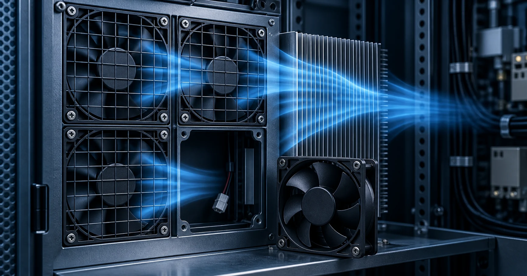
Four fans in parallel are not four times the airflow
The shortcut multiplies one fan's free-air airflow by the number of fans. That describes an ideal plenum with no resistance anywhere in the path. A real cabinet has a filter, a heat sink, a grille and a shallow plenum, and those decide where the array settles.
The relationship that is actually true is narrower than the shortcut. Two identical fans in parallel add their airflow at the same static pressure; two identical fans in series add their static pressure at the same airflow. AMCA states both as relationships for building a combined curve, and ANSI/AMCA 210/ASHRAE 51 is the standard that rates the single fan those curves are built from. Since 2023 the array has a rating standard of its own: ANSI/AMCA 270-23, Laboratory Methods of Aerodynamic Testing Fan Arrays for Rating, written as an adjunct to 210/51 because a fan wall is not a fan.
The combined curve is only half of the picture. The other half is the system curve, which is the resistance of everything the air has to pass through. Every filter, coil, heat sink, louvre and grille contributes a pressure loss that grows with roughly the square of the flow. Where the combined curve crosses the system curve is the only point the array can run at, and it always sits to the left of the ideal point.
In the worked example used throughout this article, a single fan settles at 1 000 m3/h against 167 Pa. Two identical fans do not deliver 2 000 m3/h; they settle at 1 225 m3/h and 250 Pa. Four do not deliver 4 000 m3/h; they settle at 1 309 m3/h and 286 Pa, which is 1.31 times the airflow of one fan for 2.24 times the air power. The shortcut predicts a point that is not on the system curve at all, which is why no fan can ever operate there.
N+1 is a thermal statement, not a count. Writing four fans with one spare on a drawing says nothing until three things are fixed: the heat the electronics reject, the ambient the site reaches, and the state of the filter at the end of its service interval. Until all three are stated, N+1 has no airflow value attached to it. Related reading: fan walls and N+1 airflow in data centers.

The combined curve adds airflow at one pressure, not airflow ratings
A combined curve is built by adding the airflow of every fan at the same pressure. That is arithmetic on the curve, not on the free-air number printed in a catalogue.
For identical fans the construction is mechanical: read each fan's curve at one pressure, add the airflow values, and repeat at the next pressure. The result is a curve that sits to the right of the single-fan curve and meets the vertical axis at the same shut-off pressure. Nothing about the shape is invented, which is why the combined curve is a legitimate engineering object and the multiplication shortcut is not.
Then intersect it with the system curve, and the returns flatten quickly. In the model used here, one fan delivers 1 000 m3/h at 167 Pa and four deliver 1 309 m3/h at 286 Pa. The second fan buys 225 m3/h, the third buys 61 m3/h, and the fourth buys 23 m3/h, which is 1.8 % of what three fans already delivered. The fourth fan costs a quarter more installed hardware, a quarter more damper sets and 5.5 W more air power for that 1.8 %.
This is the reason an array is not sized on airflow. Four fans are chosen because the site needs one fan out to still cool the load, because the load varies widely and staged control saves energy at part load, or because the mechanical space is shallow and a wall fits where a scroll does not. ebm-papst frames its FanGrid range in exactly those terms: several small fans instead of one large one, giving redundancy and fail-safe operation, adapting more easily to the air performance actually required, with stepless speed control.
The counterweight is that the model above is one illustrative quadratic curve and one quadratic system curve. A real fan with a pronounced dip, a system with a filter that loads over its service interval, and a plenum that does not distribute evenly will all move these numbers. The point of the arithmetic is to show which question to ask, not to select a fan. See also how to read a fan P-Q curve.

| Fans fitted | Airflow delivered | Pressure at that point | Air power used | Change against one fan |
|---|---|---|---|---|
| 1 | 1 000 m3/h | 167 Pa | 46 W | Baseline |
| 2 | 1 225 m3/h | 250 Pa | 85 W | +22 % airflow, +84 % air power |
| 3 | 1 286 m3/h | 276 Pa | 98 W | +29 % airflow, +113 % air power |
| 4 | 1 309 m3/h | 286 Pa | 104 W | +31 % airflow, +126 % air power |
When a fan stops, the other fans move to a different point on their curves
Losing one fan does not simply subtract its share. The system curve has not moved, so the remaining fans settle further out along their own curves, where the flow is higher and the power may be higher too.
Greenheck states the effect directly: with fewer fans running, the system line crosses the fan curve further out to the right than it does with all the fans running, so the motors of the fans left running have to be sized by taking into account the shape and the slope of the horsepower curve in that region. That sentence is the whole reason a redundancy test has to include current and temperature, not just airflow.
The two directions are both real. With a vane axial fan the shaft power may fall as the survivors move out along the curve. With a forward curved fan the power rises, because the horsepower characteristic keeps climbing with flow. So the assumption that the surviving fans will be lightly loaded is not a property of fans in general; it is a property of the particular curve that was selected.
In the model used here, three fans running of four deliver 1 286 m3/h against 276 Pa. Each survivor now carries 429 m3/h where it carried 327 m3/h in the full array, which is 31 % more airflow and 26 % more air power per fan. The array gave up 1.8 % of its airflow and every surviving motor moved to a harder working point. A design that was validated only for airflow would not have noticed either change.
The practical consequence is a test list rather than a calculation. Run the array with one fan out at the worst ambient and the loaded filter, and record the airflow, the current in each surviving fan, the temperature of each surviving motor, and the speed each fan actually reaches. Then check whether each survivor is still on a stable part of its curve, and whether the controller has any headroom left. Related reading: fan tray failure validation.
The failed fan is an opening unless something closes it
In a parallel array the fans share a common inlet and a common outlet plenum. Take one fan out and the plenum pressure now pushes air backwards through it.
Greenheck is explicit about the hardware requirement: fans in parallel should have some form of isolation damper to prevent air from an energised fan from going back through a fan that is not energised. The damper has a second job, which is to stop a windmilling fan being brought to a halt and then spun up again, because that sequence is hard on the fan, the motor and the structure.
The damper type follows the fan type. Backdraft or opposed-blade control dampers go at the discharge of double-width centrifugal fans. Butterfly dampers are common at the discharge of tubular inline fans. Isolation dampers for plenum fans belong further away from the fan, either upstream or downstream, because a damper close to the impeller costs pressure; Greenheck's diagrams show that distance as 1.5 D to 2 D. Where windmilling is the problem rather than reverse flow, a mechanical back stop clutch is the alternative.
The reverse path is worth putting a number on, because it is invisible in every array curve. Take a 300 mm fan opening, which is 0.0707 m2, in a plenum held at 286 Pa with air at 1.15 kg/m3. A free opening at that pressure would pass a velocity of the square root of two times 286 divided by 1.15, which is about 22 m/s; at a discharge coefficient near 0.6 that is roughly 3 400 m3/h, more than two and a half times what the whole array is moving. The stopped fan is itself a large resistance and blocks most of that, so the real reverse flow is far smaller. The number matters because it shows the reverse path is not negligible and cannot be read off the combined curve.
A reverse path does two things that a flow measurement at the outlet will not show. It short-circuits part of the airflow, so the plenum profile tilts away from the failed bay and some electronics see less air than the outlet figure suggests. And it spins the dead impeller backwards, which turns the next start into a shock load. Both are reasons to treat the isolation device as part of the fan selection rather than as an accessory.
| Fan type | Where the isolation damper goes | Damper type listed |
|---|---|---|
| Double-width centrifugal | At the discharge | Backdraft or opposed-blade control damper |
| Tubular inline, axial or mixed flow | At the discharge | Butterfly damper |
| Plenum fan | Further from the fan, upstream or downstream, 1.5 D to 2 D | Chosen for the lowest loss at the installed airflow |
| Any fan that can windmill | Not a damper position but a separate device | Mechanical back stop clutch |
The array is bigger than the fans in it
A fan is rated in a laboratory setup with defined approach and discharge conditions. An array is rated as an assembly with a common inlet or outlet plenum. Everything between those two statements is where fan walls lose performance.
AMCA Publication 201-23, which supersedes 201-02 (R2011), covers how fans are tested and how their ratings are calculated and published, reviews the reasons performance falls once a fan is installed in a system, and gives allowances called system-effect factors that designers are expected to apply. The 2023 edition revised the definition of outlet system effect on the basis of AMCA's own research, which is a reminder that this is an empirical correction rather than a tidy formula.
ANSI/AMCA 270-23 makes the array boundary explicit. It applies to fans with a common inlet or outlet plenum and it allows the rating to state partitions between fans, appurtenances or design features that affect aerodynamic performance, and speed controllers serving individual fans, groups of fans or the whole array. The number you get is therefore a number about an assembly, and the assembly is what has to be reproduced in the cabinet.
What goes wrong in practice is usually geometry. An approach that is not uniform across the wall, one fan pushed against a side panel, a partition that stops short of the plenum, a discharge that turns immediately with no straight length, or a filter whose face velocity varies across its area. Unequal loading and unequal velocity profiles feed each other: Greenheck notes that unequal loading gives different motor loads and creates unequal velocity profiles in the plenum, which can in turn produce a system effect on every fan in the wall.
The measures that address this are unglamorous. Partitions between fans where the plenum is wide. Approach and discharge kept clear by roughly the distances the manufacturer shows for the fan type. The isolation damper moved away from the impeller. And a velocity traverse across the wall at the worst filter condition, because a single measurement at the outlet cannot see a tilted profile. Related guide: static pressure in a fan system.
The states an N+1 design has to be tested in
Redundancy is proved by measurement in every state the system will actually see, not by counting fans on a drawing.
The states are not optional. All fans running is the design case. One fan out is the case the redundancy was bought for. Staged operation is the case the part-load savings depend on. The loaded filter is the case that arrives three months after commissioning, not the day the cabinet was built. Service isolation is the case a technician creates on purpose. Sound is on the list too: Greenheck's own closing questions ask whether the sound level is acceptable under all operating conditions, not only at the design point.
For each state, the record should carry airflow, static pressure, the temperature at the hottest component, the current in every running fan, the speed every fan actually reaches, and the response of the alarm system. A test that records only total airflow cannot distinguish between four fans sharing the load equally and three fans carrying the array while one sits dead in the wall.
ANSI/AMCA 270-23 gives the array the same treatment that 210/51 gives a fan, and the detail of what it allows to be declared is the useful part. Direct-drive transmissions only. Optional partitions between fans. Optional appurtenances or design features that affect aerodynamic performance. Optional speed controllers on individual fans, on groups, or on the whole array, with fan electrical power reported either per fan or for the array as a whole. In other words the standard expects the rating to say which of those the assembly actually has, because each one changes the number.
That expectation is worth copying into a specification. If the array on site has partitions and the rated assembly did not, the rating does not describe the installation. If the controller runs groups of fans and the rating was for the whole array on one signal, the same applies. The tested assembly and the delivered assembly have to be the same object. Related guide: fan sample validation in the real enclosure.
| Test state | What to prove | Evidence to record |
|---|---|---|
| All fans running | The airflow the load needs is delivered inside the stable range | Array airflow and static pressure at the worst filter condition |
| One fan out | The load is still cooled and no harmful reverse flow is present | Airflow, hot-spot temperature, current and speed of each survivor |
| Staged operation | Fans stage without hunting and without unequal loading | Control log of speed, current and plenum pressure at each stage |
| Loaded restriction | Margin still exists at the end of the filter service interval | System curve measured with the filter loaded |
| Service isolation | The isolated fan is sealed and the array stays safe | Damper or valve position, isolation check, restart current |
| Every state | The sound level at the boundary is acceptable | Installed sound measured at the boundary, one-third octave |
Control decides whether the array behaves as one fan or as four
One speed signal to every fan is the simplest arrangement and the easiest to balance. Individual control adds range and adds failure modes of its own.
Matched speed is what makes the ideal combined curve close to reality. If every fan is on the same signal and every fan has the same curve, they all sit at the same point, the split between them is predictable, and the velocity profile across the plenum stays even. This is the arrangement to choose first, and it is the one the arithmetic in this article assumes.
Individual control is what makes a fan wall valuable at part load. ANSI/AMCA 270-23 explicitly allows speed controllers on individual fans, on groups, or on the whole array. Running a subset at full speed while the rest slow down lets a large array turn down much further than a single fan can without leaving its efficient range, which is where the energy saving comes from. ebm-papst makes the same argument for its FanGrid range: several adjustable fans adapt more easily to the air performance actually required, which raises efficiency at every operating point.
The risk is unequal loading. Two fans at different speeds sit at different points on their curves, and the fan that is pushed furthest has the highest motor load and the highest noise. If a fan is pushed into the pressure region where its curve has a dip, it can hunt back and forth across the peak looking for an operating point, which shows up as a slow oscillation in speed and current rather than as a clean failure. Greenheck's guidance is to keep the operating point with all fans running no higher than the lowest pressure in the dip, which also limits the unequal loading that produces different motor loads and uneven velocity profiles.
In practice that becomes three settings in the controller: a minimum speed below which a fan must not be asked to run, a staging step that never crosses the dip, and a defined restart order that brings fans up one at a time. Related guide: fan control hunting and sensor placement.
| Control method | What it gives | What it risks |
|---|---|---|
| One speed signal to all fans | Predictable split, even plenum profile, simple commissioning | No turn-down below the minimum speed of one fan |
| Groups of fans on separate signals | Deeper turn-down with staged capacity | Unequal loading if the groups are not matched to each other |
| Each fan on its own signal | Widest range and per-fan compensation | Hunting across the dip, more failure modes, longer commissioning |
| On and off staging only | Lowest part-load power at very low load | Threshold chatter and airflow steps the load may not accept |
The electrical limits move when a fan is out
Airflow is not the only number that changes with one fan unavailable. The surviving motors, the supply and the protection all see different conditions at the same moment.
The moving point on the curve is the first limit. A motor sized from the design operating point is sized for the point where all fans share the load. In the one-fan-out state each survivor is further out along its curve, and whether the shaft power rises or falls depends on the shape of the horsepower characteristic rather than on the airflow. The safe rule is to size the motor on the worst of the two states, and to check the direction of the change on the actual curve.
The second limit is the ambient the motor actually sits in. IEC 60034-1 establishes the reference conditions for rated output, an ambient of 40 °C and an altitude of 1 000 m, and requires derating outside them. A fan wall sits inside the plenum it is feeding, so the motor is cooled by air that has already been warmed by the electronics upstream of it. Using the room temperature as the motor ambient is one of the easiest ways to lose margin that was never there.
The third limit is the electrical topology. Four fans on four feeds with four sets of protection mean an electrical fault takes one fan and the array keeps running. Four fans on one feed mean the same fault takes the whole array, and the redundancy that was paid for on the air side does not exist in practice. Power segmentation belongs in the redundancy discussion next to the fan count. Related reading: 48 V DC fans compared.
The last limit is detection. A stopped fan in a four-fan array changes the airflow by under 2 %, which is inside the tolerance of most airflow measurements and well inside the tolerance of a pressure reading at the outlet. Without per-fan feedback, a failed fan can sit unnoticed until the next one fails and the array finally loses the load. Per-fan speed feedback compared against the commanded speed is the only signal that separates a healthy array from a lucky one. Related guide: TACH and RD fault validation.
| Limit to check | Why one failure moves it | How to hold margin |
|---|---|---|
| Motor thermal margin | Surviving fans move further out along their own curves | Size the motor on the one-fan-out state, not the design state |
| Ambient seen by the motor | Motors sit in the plenum they are feeding | Use the plenum air temperature, not the room temperature |
| Supply and protection | A shared feed lets one fault take the whole array | Separate feeds and protection per fan or per group |
| Fault detection | One dead fan of four changes airflow by under 2 % | Per-fan speed feedback compared with the commanded speed |
| Restart after a stop | A windmilling impeller is spun backwards by reverse flow | Isolation device plus a defined restart order |
More motors add acoustic sources, and the installed figure is the one that counts
An array of small fans is often quieter than one large fan, and often not. The difference is how many sources there are and how evenly they are loaded.
The arithmetic of identical sources is simple and it is a floor rather than an answer. Doubling the number of identical fans running at the same point adds 10 times the logarithm of two, which is 3 dB. Four fans add 6 dB, and nine add 9.5 dB. That sum assumes every fan is at the same point on the same curve, producing the same sound power, and radiating into the same space without interacting.
Three effects push the installed array above that sum. Blade-pass tones from nominally identical fans can coincide and stack into a tone that stands above the surrounding spectrum. Two fans running at slightly different speeds produce a beat at the difference frequency, which is audible even when neither fan is loud. And a shared plenum panel or a common frame carries structure-borne sound that never passes through the air path at all, so it is not in the fan data.
The rating standard is a laboratory method and says so. ANSI/AMCA 300-24, Reverberation Room Methods of Sound Testing of Fans, supersedes 300-14, requires new test data to be recorded in one-third octave bands, and states that the test setups establish laboratory conditions which can rarely be met in a field situation, and that the standard is not intended for field measurements. A catalogue sound power level for one fan is therefore a starting point for a prediction about the array, not a measurement of it. One-third octave data is what makes the tone effects visible; a single dBA figure hides them.
Efficiency regulation attaches to the installed equipment as well. ASHRAE 90.1 sets limits on fan system power as a function of airflow, and an array that runs every fan at full speed at part load can miss the intent of those limits even while each individual fan is efficient. Staging is where the array earns its place, and it is also where the acoustic behaviour at part load has to be checked, because a three-fan state has a different tone structure from a four-fan state. Related guide: fan noise in a real enclosure.
| Source | What it adds | How to check it |
|---|---|---|
| Identical fans at one speed | 3 dB for two, 6 dB for four, 9.5 dB for nine | Power sum of the individual sound power levels |
| Blade-pass tones that coincide | A tone that stands above an otherwise smooth spectrum | One-third octave data rather than a single dBA figure |
| Slightly different fan speeds | A beat at the difference frequency | Per-fan speed log at the operating point |
| Shared panels and structure | Structure-borne paths around the air path | Sound pressure measured at the boundary, not in the plenum |
An array buys redundancy and part-load range, and costs a plenum and more parts
One large fan and a wall of small fans can meet the same airflow and the same pressure. They are not equivalent in what they do at part load, in service, or in failure.
What the array buys is real. Redundancy without a second full-size fan and its ductwork. Part-load efficiency, because at low load a subset of fans runs near its best point instead of one fan turning down into a poor region. A shorter cabinet, because the fan section is a wall in the plenum rather than a scroll beside it. And service in which a module is replaced rather than a fan and its drive.
What it costs is also real, and it is mostly parts and knowledge. Many more motors, guards, connectors, damper sets and control channels, each with its own failure mode. A plenum that has to distribute air evenly across a wall, which is a design task in itself. More acoustic sources that can coincide or beat. And a failure mode that is genuinely harder to see, because one dead fan of four changes almost nothing measurable at the outlet.
ebm-papst states the case for the array from the side of a manufacturer that also sells large fans: several small fans in parallel instead of one large fan give redundancy and fail-safe operation, and several adjustable fans adapt more easily to the air performance actually required, so efficiency rises at every operating point, with stepless speed control. That is the same argument this article makes from the curve, expressed in product terms.
The decision test is short. Choose the array when the site has to keep cooling with one fan out, when the load varies widely, or when the mechanical space is shallow. Choose one large fan with a standby when the space is deep, the load is steady, and there is somewhere to put a second full-size unit, because it has fewer motors, fewer dampers and fewer things to get wrong. Related guide: EC and AC fans in data centers.
| Property | One large fan | Array of small fans |
|---|---|---|
| Redundancy | A second full-size fan and its ductwork | One extra module in the same wall |
| Part-load efficiency | One fan turning down, often away from its best point | Fans staged on and off, each near its best point |
| Cabinet length | Long, to house the scroll | Short, a wall across the plenum |
| Service | Replace a large fan and its drive | Replace one module |
| Failure points | Fewer motors, fewer dampers, fewer channels | More motors, guards, dampers and control channels |
| Air distribution | One discharge profile to manage | Even distribution across the wall has to be designed |
| Noise | One source and one set of tones | Several sources, whose tones can coincide or beat |
| Best used when | Space is available and the load is steady | Space is shallow, the load varies, or one fan out must still cool the load |
What MEGA Tech can supply, and what we need from you
We build custom DC and EC fans, axial and backward-curved centrifugal, and we select an array by operating condition rather than by part number.
Taking the combined curve seriously is the whole method. When you send us an array requirement, we work from the fan curve at the actual speed, the system resistance with the filter loaded, and the fault state you specify, and we report the settled operating point for the full array, for the one-fan-out state and for the staged states in between. We can supply matched modules on a common speed signal, per-fan tachometer or rotation detection for fault reporting, backflow protection matched to the module rather than bought separately, partitions where the plenum is wide, and a mounting pitch and approach that let the wall behave as the rated assembly.
What we need from you is the list that turns a fan enquiry into a fan selection. The airflow the load needs and the static pressure at that airflow. The ambient temperature and the altitude of the site. The supply voltage and the tolerance it is held to. The control interface, whether that is a PWM input, a 0 to 10 V signal, a speed command over a fieldbus, or a simple on and off. The connector and the wiring access in the enclosure. The space the fan wall can occupy, including the depth in front of and behind the impeller rather than only the wall opening. The sound limit at the boundary. The life assumption in hours and the operating profile behind it. And the fault state to be proved, which includes naming which fan counts as the spare and what the remaining fans are allowed to do while it is out.
Where our boundary is. We do not design the control cabinet, the filter, the heat exchanger or the enclosure, and we do not certify the thermal performance of your complete assembly. What we can do is select the fan, build a sample, and validate the sample in the assembly it will ship in, at the pressure the system actually presents, including with one fan unavailable. If the only test available is a free-air bench, we will say so, because a free-air figure is not the figure the plenum will produce.
One request we get often deserves a direct answer. A replacement fan with the same frame size and the same free-air rating is not interchangeable with the fan it replaces in a parallel array. The combined curve depends on the shape of each fan curve, not on its endpoints, so a substitute with a different curve shape moves the settled point of the whole array and can push a surviving fan outside the stable range. Send us the curve of the fan being replaced and the resistance of the array, and we will match both. Related reading: replacing a fan and validating the operating point.
- Send the fan curve, not only the free-air airflow, so the combined curve can be built.
- State the resistance with the filter loaded, at the end of its service interval.
- State the fault state to be proved: which fan is the spare, and what the rest may do meanwhile.
- Say whether the fans share one feed and one protective device, or have separate protection.
- Give the plenum depth in front of and behind the impeller, not only the wall opening.
- Name the sound limit at the boundary and the speed range the controller will use.
Engineer FAQ: parallel fans and N+1 cooling
The array is a system with its own aerodynamic, electrical and acoustic behaviour. These are the questions that come up most often.
Q: Do two identical fans double the airflow? A: No, not in an installation. Their ideal combined curve adds flow at equal pressure, and the shared system curve then decides where the array settles. In the worked example here, four fans delivered 1.31 times the airflow of one, not four times.
Q: Is N+1 simply one fan disconnected? A: No. N+1 is a statement about airflow, motor load and component temperature in the one-fan-out state at the worst ambient and the loaded filter. A fan that is electrically isolated but hydraulically wide open is not a spare, it is a reverse path.
Q: Why does the airflow barely change when one fan of four stops? A: Because the survivors move further out along their curves and pick up most of the lost flow. The array gives up 1.8 % of its airflow in the model here while each surviving fan does 26 % more air power, which is why current and temperature, not airflow, are the numbers that reveal the failure.
Q: Can the surviving motors be relied on to run cooler because there is one less fan? A: Not without checking the curve. With a vane axial fan the shaft power may fall as flow rises; with a forward curved fan it rises, because the horsepower characteristic keeps climbing. Size the motor on the worst of the design state and the one-fan-out state.
Q: Does every fan in a parallel array need a damper? A: Greenheck's guidance is that fans in parallel should have some form of isolation damper to prevent air from an energised fan going back through a fan that is not energised. The damper also prevents a windmilling fan being stopped and restarted, which is hard on the fan and the motor.
Q: Should all the fans run at the same speed? A: Matched speed is easier to balance and it is what makes the ideal combined curve close to reality. ANSI/AMCA 270-23 allows speed controllers on individual fans, groups or the whole array, so unequal speeds are permitted, but they have to be validated for unequal loading and for hunting across a dip in the curve.
Q: Why can an array be noisier than the sum of its fans? A: Coincident blade-pass tones, a beat between fans at slightly different speeds, and structure-borne paths through shared panels. ANSI/AMCA 300-24 records new sound data in one-third octave bands and states that it is not a field measurement method, so an installed array has to be measured at the boundary.
Q: When is an array the wrong answer? A: When the space is deep enough for one large fan, the load is steady, and a standby fan can be installed. Fewer motors, fewer dampers and fewer control channels mean fewer ways for the design to be quietly defeated.
Questions for a design review
Take these to the review with the fan curves and the measured resistance on the table, not with a fan count.
A design review of a parallel array turns on a small number of questions, and almost all of them can be answered before anything is built. If the answer to any of them is a number the manufacturer printed for a free-air bench, that item is open.
- What airflow does the load need, and at what static pressure is that airflow required?
- What resistance does the system present with the filter loaded, at the end of its service interval?
- On the combined curve, where is the settled point with all fans running, and is it inside the stable range?
- With one fan unavailable, what airflow remains, and where does each surviving fan sit on its own curve?
- Are the surviving motors sized for the one-fan-out state, and does the shaft power rise or fall in that state?
- Is every fan in the wall fitted with an isolation device, and does it close when the fan stops?
- Can the dead fan be spun backwards by reverse flow, and what does the restart sequence do about it?
- Do the fans share one supply and one protective device, or is the fault contained to one fan?
- How is a stopped fan detected, given that the total airflow changes by under 2 %?
- What is the sound level at the boundary in each staged state, measured in one-third octave bands?
- Is the assembly that will be tested the same assembly that will be delivered, including partitions and controllers?
- What is the minimum speed each fan may be asked to run at, and where is that written in the controller setup?
