
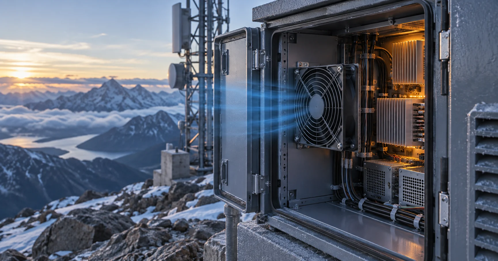
A fan bought for sea-level air has to work in the site's air
Every catalogue curve is drawn in air of a stated density. On a hot site, at altitude, the same fan is asked to do its job in air that weighs much less.
A cooling fan is selected from a curve that was measured in standard air. The motor rating on the same datasheet assumes that air as the coolant. Move the enclosure to a plateau at 2 000 m, in a summer that reaches 50 °C, and the fan has to be reconsidered, because the air entering it is roughly 28 % lighter than the air the curve was drawn in.
Thermal engineers should keep three questions apart: how much heat has to leave the enclosure, how much air temperature rise the sensitive components allow, and how much pressure the fan has to develop through the real intake grille, filter, heat sink and exhaust path. Temperature and altitude change the density of the air, so all three answers change together, and the fan has to be checked at the inlet condition it will actually see rather than at the condition it was measured in.
This is routine work in mining equipment, high-altitude telecom shelters, renewable converters, outdoor power electronics and transport systems. One enclosure can see a cold start in winter, a hot steady state in summer, a site altitude and a partly loaded filter inside a single product life. The design point is the worst credible combination of those conditions, not the most convenient one.
The rest of this article sets out what altitude and heat do to the air, what they do to the fan, what they do to the motor and the bearing, and how to turn all of that into a duty that can be quoted and then validated.

What altitude and heat change first is the density of the air
Air density follows the ideal gas law: density equals absolute pressure divided by the product of the specific gas constant and absolute temperature, with 287.05 J/(kg K) for dry air. Two site conditions enter that expression. Altitude lowers the barometric pressure, and the site temperature raises the absolute temperature. Both lower the density, and they compound.
The pressure side is the standard atmosphere. Sea level is about 101.3 kPa; at 2 000 m it is about 79.5 kPa and at 4 000 m about 61.6 kPa. These are the normal barometric pressures that IEC 60664-1 publishes in the same table it uses for electrical clearances, and they agree with the standard-atmosphere tables used across HVAC and aeronautical work. The temperature side is straightforward: at constant pressure, density falls in proportion to absolute temperature.
Put together, sea-level air at 20 °C has a density of about 1.20 kg/m3, which is the reference that most fan curves are drawn against. The same air at 50 °C is about 1.09 kg/m3, roughly 9 % lighter. Move that hot air up to 2 000 m and the density falls to about 0.86 kg/m3, roughly 28 % below the reference. At 5 000 m and 50 °C it is about 0.64 kg/m3, roughly 47 % below it.
The practical point is that temperature and altitude are not separate problems with separate corrections. They act on one quantity, the density, and every consequence in this article follows from it.
| Altitude | Barometric pressure | Air density at 20 °C | Density against sea level |
|---|---|---|---|
| Sea level | 101.3 kPa | 1.20 kg/m3 | 1.00 |
| 1 000 m | 89.9 kPa | 1.07 kg/m3 | 0.89 |
| 2 000 m | 79.5 kPa | 0.94 kg/m3 | 0.78 |
| 3 000 m | 70.1 kPa | 0.83 kg/m3 | 0.69 |
| 4 000 m | 61.6 kPa | 0.73 kg/m3 | 0.61 |
| 5 000 m | 54.0 kPa | 0.64 kg/m3 | 0.53 |
A fan moves the same volume of air at any density
The most common mistake in high-altitude work is to expect the airflow in cubic metres per hour to fall with altitude. It does not, or at least not for that reason. A fan is a constant-volume machine: at a given speed its impeller sweeps the same volume every minute whatever the air weighs, so the volumetric flow stays where it was.
What changes is everything that rides on mass. At a fixed speed and flow, the pressure the fan develops is proportional to gas density, and so is the shaft power it draws. That is the density form of the fan laws, and it is not controversial: Greenheck's temperature and altitude guidance and the ASHRAE fan chapter both treat density as an input to fan performance rather than as a change in fan capability.
The second half of the argument is what makes the result counter-intuitive. The pressure the air path demands also scales with density, because the same volume of thinner air carries proportionally less momentum into the filter, the fins and the bends. The fan curve and the system curve therefore both shrink by the same factor, and their intersection does not move sideways. The operating volumetric flow at a given speed is very nearly the same at altitude as it was at sea level.
This is worth stating carefully, because it cuts both ways. It means an altitude change on its own does not cost you cubic metres, which is why a fan does not have to be re-sized simply because the site is high. It also means that the real problem is not visible on the airflow axis at all. The airflow is unchanged in volume and reduced in mass, and it is mass that carries heat.
What the thinner air costs is cooling, not cubic metres
Heat is removed by air mass, not by air volume. The airflow needed to carry a given heat load at a given temperature rise is a mass flow, and mass flow is density multiplied by volumetric flow. If the density falls by 28 % and the fan still delivers the same cubic metres per hour, the air can carry 28 % less heat for the same temperature rise - which means the temperature rise grows by about 39 % at the same heat load.
That is the number to design against. It is also the reason high-altitude data centres and plateau inverter stations are fitted with larger fans than their sea-level twins: not because the fan has become weaker, but because the same cubic metre of air is doing less work.
The pressure side of the same argument needs one extra step, and it is the step that selecting engineers most often skip. Because the fan curve and the system curve both shrink with density, a duty expressed in actual site pressure cannot be read directly from a standard-air curve. The correct procedure is to convert the duty to its standard-air equivalent: take the pressure the site actually requires and multiply it by the ratio of standard density to site density. The equivalent pressure is higher than the site pressure, and that is the number to enter on the catalogue curve at the corrected volumetric flow.
Skipping that conversion usually produces a fan that looks comfortable on paper and runs short of pressure in service, because the curve was read at a pressure the fan will never have to develop on site and at a flow it will have to exceed.
| Quantity | Standard air at sea level | Site air at 2000 m and 50 °C | Result |
|---|---|---|---|
| Air density | 1.20 kg/m3 | 0.86 kg/m3 | 0.72 of the reference |
| Volumetric airflow delivered by the fan | 1 000 m3/h | 1 000 m3/h | Unchanged by density |
| Air mass moved per hour | 1 200 kg/h | 860 kg/h | Down by 28 % |
| Heat the air can carry at a 10 K rise | 3.3 kW | 2.4 kW | Down by 28 % |
| Air temperature rise at 3.3 kW | 10 K | 14 K | Up by 4 K |
| Volumetric airflow for the same 10 K rise | 1 000 m3/h | 1 390 m3/h | Up by 39 % |
The motor is the first limit, and the standards derate it by altitude
The fan curve is not the only document that assumes standard air. The motor rating does too, and that is where altitude bites hardest. Motor windings are cooled by the same air the fan is moving, so when the air is thinner the heat has a harder time leaving the frame, and the temperature rise for a given output goes up.
IEC 60034-1 defines the standard rating conditions as an ambient temperature no higher than 40 °C and an altitude no higher than 1 000 m. Above 1 000 m the standard requires the permitted temperature rise to be reduced, at a commonly applied rate of one per cent of the temperature-rise limit for every 100 m of additional altitude, which is about 8 % per 1 000 m. The alternative, used where a smaller frame is wanted, is to derate the output so that the same temperature rise is maintained.
NEMA MG 1 states the same idea as an output factor, and publishes it as a table. The factor is 1.00 up to 1 000 m, then about 0.97 at 1 500 m, 0.94 at 2 000 m, 0.90 at 2 500 m, 0.86 at 3 000 m and 0.78 at 4 000 m. The two conventions differ in presentation, not in direction, and both end up saying that a motor nameplate is a sea-level document.
The temperature side of the same standard matters just as much, and it interacts with altitude. Insulation systems are classed by the winding temperature they can survive - 130 °C for class B, 155 °C for class F and 180 °C for class H - and the standard gives permitted temperature rises measured by the resistance method of 80 K, 105 K and 125 K for those classes at the 40 °C reference ambient. A site at 50 °C has already consumed ten of those kelvin before altitude is considered.
The practical consequence for fan selection is that the electrical check has to be made at the site density and the site ambient, not at the nameplate condition. A fan that draws 80 % of its rated current on a cold laboratory supply can be a different proposition at 50 °C and 3 000 m, and the winding temperature, not the airflow, is the reading that decides it.
| Altitude | NEMA MG 1 output factor | IEC 60034-1 temperature-rise treatment | Air density at 20 °C |
|---|---|---|---|
| Up to 1 000 m | 1.00 | Rated condition | 1.07 kg/m3 at 1 000 m |
| 1 500 m | 0.97 | Rise limit reduced by 5 % | 1.00 kg/m3 |
| 2 000 m | 0.94 | Rise limit reduced by 8 % | 0.94 kg/m3 |
| 3 000 m | 0.86 | Rise limit reduced by 16 % | 0.83 kg/m3 |
| 4 000 m | 0.78 | Rise limit reduced by 24 % | 0.73 kg/m3 |
Electrical clearance has to grow as the air thins
Thinner air is a worse insulator. The dielectric strength of air depends on gas pressure and on the distance between conductors, so a gap that held off a given voltage at sea level can break down at altitude. IEC 60664-1 deals with this by multiplying the minimum clearance by an altitude factor above 2 000 m.
The published factors are 1.00 at 2 000 m, 1.14 at 3 000 m, 1.29 at 4 000 m, 1.48 at 5 000 m, 1.70 at 6 000 m, 2.25 at 8 000 m and 3.02 at 10 000 m, each quoted against the normal barometric pressure at that altitude. The table is reproduced in the application notes of power-electronics manufacturers such as Danfoss, which is a convenient way to see the numbers in the form a converter designer meets them.
Two consequences are easy to miss in a fan specification. The first is inside the fan: an EC fan contains a converter, and the spacing on its control board and the creepage around its terminals were chosen for a stated altitude. A fan whose electronics are rated to 2 000 m is not automatically suitable at 4 000 m, even if the aerodynamic performance is adequate, because at 4 000 m the clearances need a factor of 1.29 applied to them.
The second is in the enclosure around it. A cabinet wired to minimum clearances at sea level and then installed on a plateau needs either larger spacings, a higher-rated insulation system, or a declared lower impulse withstand voltage. That is an enclosure decision rather than a fan decision, but it is decided in the same document, and it is the reason an altitude figure belongs in the fan enquiry as well as in the cabinet drawing.
| Altitude | Normal barometric pressure | Factor for clearances | A 5.5 mm clearance becomes |
|---|---|---|---|
| 2 000 m | 80.0 kPa | 1.00 | 5.5 mm |
| 3 000 m | 70.0 kPa | 1.14 | 6.3 mm |
| 4 000 m | 62.0 kPa | 1.29 | 7.1 mm |
| 5 000 m | 54.0 kPa | 1.48 | 8.1 mm |
| 6 000 m | 47.0 kPa | 1.70 | 9.4 mm |
High temperature reaches the bearing grease before it reaches the fan curve
On the electrical side the temperature limit is a winding class. On the mechanical side it is the lubricant, and the lubricant fails long before the steel does. In the fan and blower industry, bearing failures are the dominant failure mode: Rotron, a fan manufacturer that publishes the mechanism, states that bearing failures outnumber insulation breakdowns by roughly four to one, and that the degradation is oxidative and evaporative, which makes the Arrhenius relationship approximately valid.
The rule of thumb that follows is the one worth carrying into a high-temperature specification: grease life halves for every 15 °C increase in bearing temperature. SKF states the same rule in its grease-lubrication literature, where grease life is the L10 life - the time at which 10 % of a population of bearings has failed. The consequence is that moving a bearing from 70 °C to 100 °C does not reduce the life by a third; it divides it by four.
This is why a bearing life figure without its conditions is not usable. An L10 of 70 000 hours at 40 °C says nothing about the same fan in a 70 °C enclosure, and nothing at all about a fan in an outdoor cabinet whose internal air reaches that temperature in summer. The conditions that belong with the number are the temperature, the speed, the shaft orientation, the load, the duty cycle and the test basis.
There is a second-order effect that high-altitude sites add. Reduced air pressure lowers the boiling point of the base oil and speeds its evaporation, so a grease that is adequate at sea level in the same temperature can age faster on a plateau. Against that, an outdoor site also brings solar heating, wide daily temperature swings and, at altitude, stronger ultraviolet exposure that attacks elastomer seals. None of these are captured by a single temperature figure, and all of them shorten the same lubricant life.
| Bearing temperature | Life against the 70 °C reference | What it means for a quoted figure |
|---|---|---|
| 70 °C | 1.0 | Reference condition of a published relubrication table |
| 85 °C | 0.5 | Half the hours for 15 °C more |
| 100 °C | 0.25 | A quarter of the hours |
| 115 °C | 0.125 | An eighth of the hours |
| 130 °C | 0.0625 | One sixteenth, and above most standard greases |
Cold dense air is the second overload case
The same relationship that makes hot thin air hard on cooling makes cold dense air hard on the motor. Shaft power scales with density, so a fan draws its highest power when the air is coldest and densest, not when the enclosure is hottest. A fan selected for a 50 °C summer with a comfortable margin can be overloaded on a winter start-up.
The arithmetic is simple enough to check by hand. Air at -20 °C and sea level has a density of about 1.40 kg/m3, roughly 17 % above the 1.20 kg/m3 reference. If the motor was sized at 90 % of its rating in the hot condition, the cold start can push the same fan past its rating before the windings have warmed up.
The check is therefore a two-point check on the motor: the hottest steady state at the site density, and the coldest credible start. Where the cold point governs, the usual answers are a motor with more thermal margin, a controlled start that brings the fan up gradually, or a starting damper on the air path. The last two are system decisions and sit outside a fan supplier's scope, but the fan selection has to leave room for them.
The same reasoning applies to speed control. A fan that runs at reduced speed for most of the year may never reach the cold-start condition at full power, which is one reason a PWM or EC drive with a defined start ramp can buy margin that a fixed-speed unit cannot. That margin buys nothing, however, unless the start ramp is specified with a maximum rate rather than left to the controller default.
The selection sequence for a hot or high-altitude site
Working in a fixed order keeps the density correction in the right place and stops an estimate from being mistaken for a selection. The sequence below follows the same logic as any other fan selection, with the density steps made explicit.
Start with the heat load, and bound it rather than averaging it: device losses at the duty that matters, plus solar gain where the enclosure sees the sun, plus any upstream heat that enters with the ventilation air. Then fix the allowable air temperature rise from the component that has the least margin, not from the average of the enclosure.
Next, establish the site density from the highest air temperature and the site altitude together, using the ideal gas law on the standard-atmosphere pressure. Convert the allowed rise and the heat load into a mass flow, and convert that mass flow into a volumetric flow at the site density. That volumetric flow is the one the fan has to deliver; it is larger than the sea-level figure by the inverse of the density ratio.
Build the system curve from the real air path - intake grille, filter, heat-sink fins, bends, exhaust - and convert the required duty to its standard-air equivalent pressure. Then read the fan curve at the corrected flow and the equivalent pressure, not at the site pressure. Finally, check the fan against the four limits that the airflow figure does not cover: motor temperature rise at the site density, cold-start shaft power, bearing life at the site temperature, and electrical clearance for the site altitude.
The order matters because the last three checks can all overturn a selection that looked adequate on the curve. A fan can be aerodynamically correct and still be wrong for the site, and the checks are cheap compared with a qualification test that has to be repeated.
- Bound the heat load, including solar gain and incoming warm air.
- Take the allowable air rise from the component with the least margin.
- Compute site density from the highest air temperature and the site altitude together.
- Convert heat and allowable rise into a mass flow, then into a volumetric flow at site density.
- Convert the duty to its standard-air equivalent pressure before touching the fan curve.
- Check motor rise, cold-start power, bearing life and electrical clearance as separate limits.
A worked example: 3.3 kW of losses and a 10 K air rise
Take an outdoor electronics enclosure with 3.3 kW of losses to remove, and a component limit that allows the air to rise 10 K above the inlet. On a sea-level bench at 20 °C, with a density of 1.20 kg/m3 and a specific heat of 1 005 J/(kg K), the mass flow needed is about 0.328 kg/s, which at that density is very close to 1 000 m3/h.
Now put the same enclosure at 2 000 m where the summer air reaches 50 °C. The density is 0.86 kg/m3. To keep the 10 K rise, the fan has to move the same mass of air, which now occupies more space: about 1 390 m3/h, or 39 % more volume per hour than at sea level.
The pressure side needs the conversion step described earlier. Suppose the real air path demands 200 Pa at 1 000 m3/h in standard air. At 1 390 m3/h the same path demands more, because system resistance rises roughly with the square of flow: about 385 Pa in standard-air terms. On site, because the air is 0.72 as dense, the fan only has to develop about 277 Pa to push that flow. The number to enter on the catalogue curve is therefore 385 Pa at 1 390 m3/h, and the fan will run at the same point.
If, instead, the enclosure keeps the fan that delivered 1 000 m3/h at sea level, the system still works, and that is the trap. Nothing alarms, no airflow reading looks wrong, and the volumetric flow is exactly what the sea-level calculation asked for. The air rise simply grows from 10 K to about 14 K, which may be enough to take the hottest component past its limit, and the winding and the bearing run hotter for the whole of the product life.
| Step | Standard air at sea level | Site air at 2000 m and 50 °C |
|---|---|---|
| Air density | 1.20 kg/m3 | 0.86 kg/m3 |
| Heat load to remove | 3.3 kW | 3.3 kW |
| Allowable air temperature rise | 10 K | 10 K |
| Mass flow required | 0.328 kg/s | 0.328 kg/s |
| Volumetric flow required | 1 000 m3/h | 1 390 m3/h |
| System resistance at that flow, standard-air basis | 200 Pa | 385 Pa |
| Fan pressure to develop on site | 200 Pa | 277 Pa |
| Air rise if the sea-level fan is kept | 10 K | about 14 K |
What MEGA Tech can supply, and what we need from you
We are a custom cooling fan manufacturer. We select and build axial DC and EC cooling fans, and backward-curved centrifugal units where the pressure a filter, a heat sink or a long air path demands is beyond what an axial fan can hold at the required flow. Selection is made against a stated duty - the airflow and the static pressure at that airflow, corrected to a stated density - rather than against a part number. We supply a production-representative sample so that the validation is done in your enclosure, at your site conditions, rather than on a free-air bench.
To quote a fan for a hot or high-altitude site we need the airflow and the static pressure at that airflow, together with the air temperature and the altitude that establish the density basis, and the highest air temperature the fan will see. We also need the supply voltage and its tolerance, the control, feedback and alarm interface you want, the connector and harness arrangement, the space and mounting available, the noise target and the point at which it is measured, the environment including dust, humidity and solar exposure, the expected life with its assumptions, and the electrical clearance or insulation requirement that applies at the site altitude.
Our scope ends at the cooling fan and its interface. We do not supply the enclosure, the filter or its housing, the cabinet cooling unit or heat exchanger, the unit controller or its firmware, or the safety and ingress certification of the finished cabinet. The clearance and insulation decisions inside the enclosure belong to the cabinet designer, and the derating decision for a user's own motor or converter belongs to its maker. Saying so is what makes the quotation usable, because it makes clear which party is answering for which number.
We will not tell you that a candidate is equivalent because the frame size matches. Two 92 mm fans can differ by a large factor in the pressure they hold at the flow you need, and the comparison has to be made at the same pressure, the same speed and the same density basis. That is why a hot or high-altitude duty has to be written down with its temperature and altitude, and why the sample is validated in the enclosure rather than on a datasheet.
- Send the duty as airflow plus the static pressure at that airflow, with the temperature and altitude that set the density.
- State the highest air temperature the fan will see, not the room temperature around the cabinet.
- State the site altitude, so that motor derating, bearing life and electrical clearance can all be checked against it.
- State the noise limit and where it is measured, because a larger fan bought for thin air is also a different acoustic source.
- Expect a sample that is validated in your enclosure; a free-air figure is not a validation.
Engineer FAQ: hot and high-altitude fan selection
A usable fan specification for a hot or high-altitude site is a set of boundary conditions, not a frame size and a voltage.
Q: Does the airflow in cubic metres per hour fall at altitude? A: Not because of altitude as such. A fan moves the same volume at the same speed whatever the density. What falls is the pressure it can develop and the mass of air it moves, and it is the mass that carries the heat.
Q: Then why do high-altitude installations need bigger fans? A: Because the cooling duty is a mass flow. To deliver the same mass of air per hour in thinner air, the fan has to move proportionally more volume, which means a larger fan or a higher speed.
Q: Can I correct a sea-level airflow figure by the density ratio? A: Only as a first screen, and only with the direction of the correction understood. The volumetric flow is unchanged, the pressure and power scale with density, and the required volumetric flow for a given cooling duty scales with the inverse of the density ratio.
Q: Which derating figure do I use for the motor? A: Either the temperature-rise reduction in IEC 60034-1 or the output factor in NEMA MG 1, applied as the standard states and confirmed with the motor maker. The nameplate is a 40 °C, 1 000 m document.
Q: How much margin should I leave for altitude and heat? A: Enough to cover the difference between the assumed ambient and the measured one, plus the density at the highest temperature. Where the components are already close to their limits, margin in volumetric flow is cheaper than margin bought with fan speed.
Q: Does a filter change the answer? A: It changes the system curve, and therefore the operating point. A loaded filter at altitude moves the operating point in the same direction as at sea level, but starting from a lower pressure capability, so the two effects add.
Q: What should a hot and high-altitude sample test include? A: The production-representative fan in the real or representative enclosure, with the real grille, filter and heat sink, at the highest air temperature and the lowest temperature, across the voltage range, with airflow, pressure, current, winding or case temperature, component temperature, noise and alarm response logged.
Q: When is a custom fan justified? A: When a standard fan misses the volumetric flow or the pressure at that flow for the site density, or the temperature and life conditions of the site, or the control interface, connector, mounting or environmental protection the installation needs. Customise against measured constraints, then validate the sample.
Questions for a design review
These are the questions that decide whether a hot or high-altitude fan selection will survive a design review and a field trial, and they are worth asking before the fan is ordered rather than after the enclosure has been qualified.
- What is the highest air temperature the fan inlet will see, and which measurement supports it?
- What is the site altitude, and has it been used to set the density basis rather than treated as a separate margin?
- Is the duty written as airflow plus the static pressure at that airflow, on a stated density basis?
- Has the required volumetric flow been converted from the cooling mass flow at site density?
- Has the duty been converted to a standard-air equivalent pressure before the fan curve was read?
- Has the motor been checked at the site density and the site ambient, against the derating the standard requires?
- Has the same motor been checked at the coldest credible start, when the air is densest and the shaft power highest?
- Does the bearing life quote carry its temperature, speed, orientation, load and duty cycle, or only a number of hours?
- Does the electrical clearance inside the enclosure and inside any EC fan electronics meet the altitude factor for the site?
- Is the sample test specified with the real grille, filter and heat sink, at both temperature extremes, with the readings written down before the test starts?
