
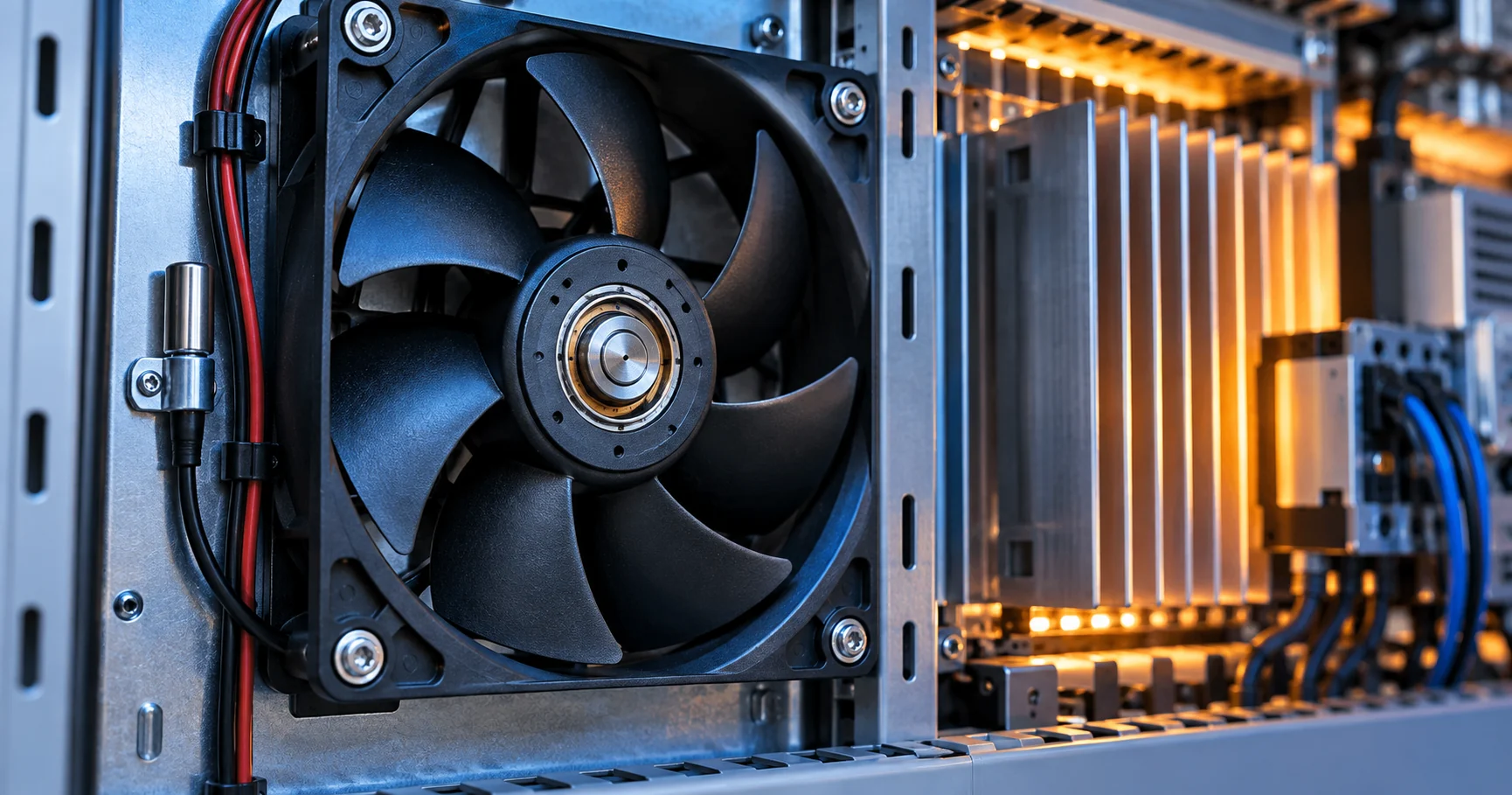
The power supply is both the heat source and the heat victim
A power supply turns its own throughput into heat, and the components that fail first — electrolytic capacitors above all — fail by temperature. The fan's job is to keep the published derating curve honest at the ambient the machine actually reaches.
Every watt a power supply delivers costs losses: switching, conduction, magnetics and rectification all leave heat inside the same enclosure that houses the most temperature-sensitive components in the design. The derating curve printed on the datasheet — the load the unit may carry versus ambient temperature — is a promise about what the cooling achieves. Where the cooling falls short, the curve is quietly wrong, and the failures surface where the thermal design did not look: in the capacitor bank, not at the heatsink the sensor watches.
The fan selection inside a power supply is therefore a coupling of two problems. The aerodynamic problem is familiar from every selection in this series: a dense internal path — heatsinks, transformer, choke, capacitor bank behind perforated vents — at a resistance the fan must cross at the required airflow. The reliability problem is specific: the cooling must reach the components whose life is temperature-exponential, not merely the ones with visible surface area, and it must do so without compromising the isolation and creepage distances that the high-voltage side mandates.
This guide walks both: what the derating curve actually promises, where the hot spots hide, how the air path and its control are selected, and how the result is validated at the states that decide. The airflow arithmetic is shared with the operating point method and the path effects with the filter loading guide.
Where the hot spots hide: the sensor map problem
Heatsinks are visible, hot and well instrumented. The components that actually limit PSU life are often cooler-looking, invisible — and exponentially more temperature-sensitive.
Electrolytic capacitors are the canonical case. Their life roughly halves for every 10 C rise at their core, and their core sits inside a can on the board, heated from below by the board and from the side by the choke — often far from the airflow path the fan sweeps. A PSU whose heatsink reads 70 C and whose capacitor bank reads 85 C has a life limit set by the 85 C component, whatever the semiconductor margins suggest. The bearing life arithmetic runs on the same rule; here the bearing is the fan's problem and the capacitor is the PSU's.
Semiconductors fail through junction temperature, magnetics through winding temperature, and connectors through contact heating — each with its own limit and its own position in the airflow. The design question is not whether sensors exist but what they can see: an NTC on the primary heatsink reports the semiconductor story and is blind to the capacitor bank two centimetres away in a stagnant corner. The sensor map is a design input to the airflow: either the air reaches the capacitor bank, or a second sensor must.
The failure pattern that results is well known in the field: a PSU that runs for years at rated load in a cool room and fails young in a hot cabinet, because the derating curve was measured with ideal airflow over the heatsink and without the stagnation zone the real enclosure imposes. Validation at the real states is the answer, and this guide closes with it.

| Component | Life limit | Where the air must reach it |
|---|---|---|
| Electrolytic capacitors | Core temperature — life halves per 10 C | The bank's position in the flow, not the board's average |
| Power semiconductors | Junction temperature | Heatsink fins in the primary flow, sensor on the sink |
| Magnetics | Winding temperature class | Choke and transformer surfaces in the directed flow |
| Connectors and busbars | Contact heating at high current | Vent design that does not starve the output side |
| The fan itself | Bearing life at real inlet temperature | Its own corner of the enclosure, often the hottest inlet |
The air path: dense, high-voltage, and unforgiving
A PSU's internal path combines high resistance with isolation constraints. The fan must move air across creepage distances, not through them, and the vents that keep fingers out also raise the resistance.
Resistance first. Perforated intake grilles, dense fin stacks, the transformer mass and the wiring harness put a PSU high on the system curve — blower territory in compact units, high-static-pressure axial fans in larger ones. The fan type selection logic applies unchanged; the PSU-specific twist is that the vents are safety features. Finger-safe grilles and isolation barriers are not removable airflow obstacles but fixed design facts, and the fan selection must cross the system curve with them in place.
Direction second. The airflow must serve two masters: the semiconductor heatsinks that want high-velocity directed flow, and the capacitor bank that wants any flow at all. A path that sweeps the heatsinks and stagnates at the cap bank delivers the derating curve of the previous section's illustration. Baffles that force a pass over the bank, or a secondary path across it, are ordinary practice — and they belong in the selection arithmetic, because they change the resistance the fan sees.
The high-voltage side sets the boundaries. Fans, clips and airflow direction may not compromise creepage and clearance distances; dust transported by the fan deposits on those surfaces, which is why filter decisions in dusty industrial sites are electrical-safety decisions as much as thermal ones — the filter loading guide covers the operating-point cost, and the site environment determines the interval. And the fan's own inlet sits wherever the enclosure puts it: in many PSUs that corner is the hottest air in the box, which the bearing selection must survive.
A worked duty point (illustrative numbers)
The coupling between airflow and component life is easiest to see on one number: the temperature of the capacitor bank.
Take an industrial PSU delivering 500 W at 90 % efficiency: 55 W of loss sits inside the enclosure. Suppose the measured path — grilles, heatsinks, transformer, wiring — imposes 65 Pa at the 60 m³/h the thermal design requires, and the fan's curve crosses there with margin at nominal voltage. At that airflow the heatsink NTC settles at 72 C; the capacitor bank, sitting behind the choke in a corner the flow bypasses, settles at 84 C.
The life arithmetic now runs on the 84 C figure. A capacitor family quoted at 4,000 hours at 105 C lives roughly 32,000 hours at 84 C — respectable, until the cabinet's preheated intake pushes the same bank to 94 C, where the expectation drops toward 16,000 hours and the product's five-year warranty is suddenly an actuarial gamble. A baffle that forces even a fraction of the flow across the bank, or a second small fan in series along that corner, moves the bank down 10 C and buys the warranty back — for less cost than any other change in the design.
The point of the worked number is the method: measure the bank's temperature, not the heatsink's, and let the Arrhenius arithmetic decide whether the fan selection is finished. A selection that ends at the NTC has answered the semiconductor question and left the life question open.
Control: the derating curve is dynamic
PSU fans do not run at one speed. The thermal control law — usually an NTC on the heatsink driving PWM duty — decides what the user hears, what the capacitors feel, and how long the fan lives.
The control objective is a moving target: hold semiconductor margins at high load, keep the acoustic profile acceptable at low load, and never oscillate between the two. A control law built on one heatsink NTC achieves the first and can miss the capacitor bank entirely — the fan idles comfortably while the caps age. A second sensing point, or a control law with a duty floor that guarantees cap-bank airflow, closes that gap.
The fan's interface contract is the same as everywhere in this series: PWM frequency range, duty-to-speed response and tach reporting must sit inside what the control firmware assumes, with the PWM control guide covering the interface and the start-up behaviour that a PSU's own brown-out and restart cycles impose on the fan. Server and industrial PSUs add redundancy: the N+1 case must carry full load at worst-case ambient — the arithmetic and its control implications are in the parallel fans and N+1 guide.
Altitude and hot ambients complete the control picture. Air thins with altitude and carries less heat per cubic metre; a PSU rated to 50 C at sea level needs its fan curve re-crossed for a 2,000-meter installation. The hot and high altitude selection guide covers the derating stack-up.
Validation: prove the derating curve at the states that decide
A PSU validates at maximum load, worst-case ambient, installed orientation — with instrumentation on the components the sensors cannot see.
The states that decide are the ones the datasheet's curve was never measured at: full load at the top of the ambient range, inside the real enclosure or the customer's rack, with the filters loaded and the intake air preheated by the machine below. At that state, the thermocouples go where the sensors do not reach: the capacitor bank core, the choke windings, the connector busbars. The heatsink NTC's reading is recorded too — it becomes the calibration between what the controller sees and what the components feel.
The fan's contribution is validated in the same run: duty at each state, tach response across the restart and brown-out cycles a PSU imposes, acoustic level at the operator position for desktop and wall-mount formats, and a bearing-life cross-check against the inlet temperature the fan actually experienced. A unit that passes with the fan at its duty ceiling is a unit with no acoustic or life margin left — the selection revisits the fan, not the test.
The endurance re-check closes the loop exactly as it does for every product in this series: agreed hours at the real thermal state, then repeat the measurements. For a PSU the endurance list adds the capacitor bank's temperature record — the component whose life the whole validation is ultimately protecting. The postmortem method shows what the field failure looks like when this step is skipped.
- Full load, worst-case ambient, real enclosure: the derating curve verified, not assumed.
- Instrumented hot spots: capacitor bank core, choke windings, busbars — where sensors cannot see.
- Fan behaviour: duty at each state, tach through restart cycles, acoustic level at the operator position.
- N+1 case: full load held with one fan failed, detection and reporting confirmed.
- Endurance re-check: agreed hours at the real state, then the measurements repeated.
What MEGA Tech does with PSU cooling projects
We manufacture the high-static-pressure fans and blower solutions that power supplies run on, from open-frame industrial units to sealed server PSUs, and we work from the derating curve backwards.
What we do: send us the derating promise, the enclosure path and the hot-spot map — or the PSU to measure — and we propose fans that cross the real system curve with every safety feature in place, provide measured P-Q and acoustic data, and support the validation protocol including the instrumented endurance re-check. Where the duty needs a custom answer — speed class, connector, coating, sealing — we build the variant and qualify it.
What we need from you: the load and ambient envelope the derating curve must survive, the internal path geometry or the unit itself, the control interface and its duty law, the site environment (dust, altitude, orientation), and the acoustic limit where the product is heard.
Where our boundary is: we do not supply power conversion electronics, enclosures, safety engineering or thermal controllers. Our scope is the fan — and the measured data that lets your team keep the derating curve honest in the machine.
Recommended Fan Starting Points
These catalogue series may be suitable starting points for this application. Final selection depends on the installed airflow, static pressure, voltage, noise target and operating environment.
Request a sample for validation on your equipment.
Engineer FAQ
The questions engineers actually ask about PSU cooling, with the short engineering answers.
Q: The PSU meets its derating curve on the bench. Why did it fail in the field? A: The bench airflow is not the enclosure airflow. Stagnation at the capacitor bank, preheated intake air and loaded filters all move the real operating point — validate at the installed state with instrumentation on the sensitive components.
Q: Which fails first, the fan or the capacitors? A: Whichever runs hotter relative to its life curve. Both follow the same halving-per-10 C arithmetic, and both are set by the same airflow. A selection that cools one and stagnates the other merely chooses which failure the field sees first.
Q: Can I use a quieter fan and accept a lower derating at high ambient? A: Yes, if the product's specification says so explicitly. The derating curve is a promise to the customer; a quieter fan rewrites it. What is not acceptable is a quieter fan with the old curve still printed.
Q: Why do PSUs use blowers when axial fans are cheaper? A: Height and resistance. Compact and 1U formats have dense paths and safety grilles that demand static pressure; the crossing-point arithmetic settles it the same way as any type selection.
Q: Does the fan need PWM in a PSU? A: The thermal control law needs speed control — PWM driven from the heatsink NTC is how the acoustic profile and the life budget coexist. A fixed-speed fan forces the design to choose one at the expense of the other.
Q: What is the first thing to check on a field-failed PSU? A: The capacitor bank's environment: its position in the airflow, its measured temperature history and the filter state. The derating postmortem method shows the sequence.
Questions for a design review
Take these to the review with the derating curve, the enclosure sketch and the hot-spot list on the table.
PSU cooling reviews that only check the heatsink produce units that fail in the capacitor bank. These questions close both layers.
- Has the derating curve been verified at full load, worst-case ambient, inside the real enclosure with loaded filters?
- Where are the capacitor bank, choke and busbar relative to the airflow — and which sensors can see them?
- Does the fan curve cross the system curve with every finger guard and isolation feature in place?
- Does the control law guarantee airflow over the temperature-sensitive components at idle duty, not just at full load?
- Does the N+1 case hold full load at worst case, with failure detection and reporting confirmed?
- Has the fan's bearing life been cross-checked against the inlet temperature it actually experiences in the box?
- Does the endurance re-check run at the real thermal state and record the capacitor bank's temperature history?
