The first selection question is the fan type, not the size
Frame size, bearing type and brand all come second. The first decision in every cooling fan selection is which type of fan the air path needs — axial, centrifugal blower or backward-curved centrifugal — and the air path decides it, not preference.
Engineers who arrive at a fan catalogue usually arrive with a size in mind: an 80 mm or 120 mm square, 25 mm thick. But two fans of the same frame size can sit at completely different points on the pressure-airflow map, because the type — how the fan moves air — sets the shape of its curve. An axial fan and a forward-curved centrifugal blower with the same footprint are not alternatives in the same bracket; each is the right answer for a different air path and the wrong answer for the other one.
The cost of choosing the type by habit instead of by path shows up quietly. An axial fan installed where the resistance demands a blower will spin fast, sound loud, and still deliver less airflow than the datasheet promised — because its curve collapses against the resistance. A blower installed where a straight-through path would let an axial fan do the work wastes pressure capability, costs more, and adds a 90-degree turn to a path that did not need one.
This guide defines the three types by their flow geometry, shows how the air path — its resistance, its direction changes, its density of components — selects the type, and works the arithmetic that proves the choice. The same P-Q method underlies the replacement selection method; here it is applied to the earliest and most consequential question in a new design.
What the three types actually are
The type is the flow geometry: which way the air turns, and what that costs in pressure capability versus airflow.
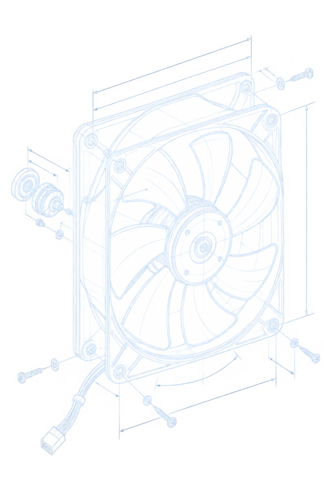
An axial fan moves air parallel to its shaft — air enters the front face and leaves the back face with almost no direction change. That geometry moves large volumes of air efficiently, but the pressure it can build is limited: the blade design that favours free flow cannot sustain much static pressure. Axial fans dominate electronics cooling wherever a straight-through path exists — panel fans, rack exhausts, enclosure ventilation — precisely because the path imposes little resistance and the fan returns maximum airflow for it.
A forward-curved centrifugal blower — the compact drum type common in electronics — takes air in axially at one end and throws it radially outward through a scroll, turning the flow 90 degrees. The turn and the scroll let it build several times the static pressure of an axial fan of comparable footprint, at lower free-air flow. That is the fan of dense paths: 1U servers, compact power supplies, projector light engines — anywhere the air must be pushed through tight channels, dense fin stacks and narrow vents.
A backward-curved centrifugal fan turns the flow the same 90 degrees but with blades that lean against the direction of rotation. The geometry is the most aerodynamically efficient of the three and sustains the highest pressures, at larger diameters and higher speeds — the fan of long ducts, high-resistance cabinets and industrial air handling. In electronics enclosures it appears where the path is genuinely severe; where it is not, its size and speed are an expensive over-answer.

| Type | Flow geometry | Characteristic strength | Watch out for |
|---|---|---|---|
| Axial | Air flows straight through, parallel to the shaft | Highest airflow at low resistance | Curve collapses quickly against high static pressure |
| Forward-curved blower | Axial inlet, 90-degree radial turn through a scroll | Compact high pressure at moderate flow | Lower free-air flow; needs a scroll-side clearance in the mount |
| Backward-curved centrifugal | Axial inlet, 90-degree turn, blades lean against rotation | Highest pressure and efficiency, stable curve | Larger diameter and speed; over-specified for easy paths |
How the air path selects the type
Three properties of the path decide: how much resistance it imposes, how many times it turns the air, and how much room it leaves for the fan to work.
Resistance first. The system resistance curve rises with the square of velocity: double the airflow through the same vents and the pressure quadruples. A straight-through cabinet with open vents and sparse components sits low on that curve — axial territory. A 1U chassis full of dense heat sinks, cable bundles and electromagnetic shielding sits high — blower territory. The pressure drop budget guide shows how to estimate which side of the line a path falls on before any fan is chosen.
Direction second. Every turn the air must make — across a board, out a back panel, through a duct — costs pressure and adds recirculation risk. An axial fan adds no turns; a blower builds the turn into itself, which is why it wins where the chassis geometry already forces air to change direction in a short distance. If the natural path is straight, fighting it with a radial machine buys nothing.
Room third, and it cuts both ways. A blower needs clearance on its scroll side and a defined outlet; an axial fan needs straight duct run on both faces to develop its flow. A fan starved of inlet clearance underperforms its curve no matter which type it is — the installation pitfalls guide collects the classic cases.
Measure the path: ten minutes that decide the type
The type decision does not need a wind tunnel. A hand-held anemometer, a differential pressure gauge and a smoke pencil answer it in the machine, before any fan is ordered.
Airflow first: traverse the vent with an anemometer — a grid of five to nine points across the opening, averaged — and multiply the mean velocity by the free open area to get the delivered airflow. This is the number the current fan actually delivers against the real resistance, and it is the minimum the replacement type must beat. The airflow measurement guide details the traverse method and its common errors, edge vortices and grille losses chief among them.
Resistance second: a differential pressure tap across the filter, or across the assembly from inlet to outlet, puts a number on the resistance the path imposes at the measured flow. One point is enough to fit the system curve's shape when combined with the square-law assumption, and the fitted curve is what candidate fan curves get crossed against. Where the filter loads over an interval, take the reading at both clean and loaded states — the type must survive the loaded one.
Direction third: a smoke pencil or incense trace at the inlet and outlet shows where the air actually goes. Straight through — axial territory. Turning within a short distance — the geometry that favours a blower. Recirculation loops, dead corners and bypass leaks show up in the smoke trace before they show up in any temperature log, and some of them are fixable with baffles rather than a different fan.
Write the three numbers down: delivered airflow, resistance at that airflow, and the path's turn geometry. Any supplier who receives them can propose the right type; any supplier who answers without asking for them is selling a footprint.
| Measurement | Method | What it decides |
|---|---|---|
| Delivered airflow | Anemometer traverse across the vent, mean velocity times free open area | The minimum the new type must beat |
| System resistance | Differential pressure tap across filter or assembly, clean and loaded | Which curve shapes survive the path |
| Path geometry | Smoke trace at inlet and outlet | Turns, recirculation and bypass — the axial-versus-blower question |
The arithmetic that proves the choice
The type decision is testable on paper: put each candidate's curve against the system curve and read the crossing point. The bigger free-air number usually loses.
Worked example (numbers are illustrative of the method, not any specific product). A 1U chassis pushes air through a dense path; the measured system resistance is P = 0.05 Q² (Pa against m³/h), and the thermal budget requires 55 m³/h at that state. Candidate A is an 80 mm axial fan: 300 m³/h free air but only 40 Pa of shut-off pressure. Its curve crosses the system curve at about 28 m³/h — barely half the requirement, even though its free-air number is more than five times the requirement. Candidate B is a forward-curved blower of similar footprint: 90 m³/h free air but 300 Pa of shut-off. Its curve crosses at about 59 m³/h — above the requirement with margin, at a lower noise than the axial fan straining at full speed.
This is the canonical failure of free-air selection: the axial fan's headline number is real — at zero pressure, which no real machine provides. Against the dense path it collapses. The blower's modest free-air number survives the resistance and delivers the airflow the thermal budget asked for. The P-Q curve guide walks the reading of both curves; the operating point method applies the same arithmetic to replacement selection.
Where the honest answer is that one fan of any type cannot cover the duty, the path itself can change: split the flow into two shorter parallel paths, add a second fan in series for pressure or in parallel for flow — the parallel fans and N+1 redundancy guide covers the arithmetic and the control implications of both arrangements.
The dimensions the type decision does not cover
Type first — then acoustics, dust, orientation and control still have to be checked against the same machine.
Acoustics: an axial fan near its pressure limit is loud — the curve collapse is accompanied by turbulence and a rising blade-pass tone. A blower running mid-curve is quieter at the same delivered airflow, which is one more reason dense paths favour it. Conversely, forcing a blower into an easy path means running it at low duty, where some designs hum. The acoustic check belongs in the real housing, across the duty sweep, as in every selection.
Dust and orientation: axial fans expose their bearings to the incoming airstream; horizontal shafts in dusty paths accumulate lint on the blades and in the bearing zone. Blowers ingest at the end bell and can tolerate filtered inlets differently. Orientation changes the bearing load and, in high-temperature paths, the lubricant behaviour — the high temperature selection guide covers the derating.
Control: all three types are available with tach and PWM interfaces, but the duty-to-speed response differs by type and family. A controller tuned for one curve shape needs its assumptions re-verified when the type changes — the PWM control guide covers the interface contract.
What MEGA Tech does with fan type selection
We manufacture axial fans, centrifugal blowers and custom configurations, and the first thing we ask about a new project is the air path — because the type decision is worth more than any other single choice in the thermal design.
What we do: send us the path description — geometry, vents, components, filters, the temperature budget — and we will tell you which type the path is asking for, propose candidates within that type with measured P-Q data, and produce samples for validation in the real assembly. Where the path is unusual we build custom configurations: frame modifications, custom speed classes, interface and connector variants.
What we need from you: the path geometry and resistance estimate (or the machine to measure), the thermal budget at worst case, the noise limit at the operator position, and the control interface the board uses. A photo or sketch of the airflow path with the vents marked shortens the first conversation considerably.
Where our boundary is: we do not supply liquid cooling loops, heat pipes, cabinet safety design or fan controllers. Our scope is the fan — and the measured data that lets your team verify it in the machine.
Engineer FAQ
The questions engineers actually ask about fan type selection, with the short engineering answers.
Q: Is a blower always the right choice for a 1U chassis? A: Almost always, because the path is dense and the turns are tight — but the proof is the crossing point of the curves, not the form factor. Measure the resistance; a well-vented 1U with few components may still be axial territory.
Q: My axial fan delivers far less air than the datasheet says. Is the fan faulty? A: Usually not. Its curve has collapsed against a system resistance higher than the fan's pressure capability. Either the path was misestimated or the type is wrong; the crossing point arithmetic will show which.
Q: Can I put two axial fans in series to replace a blower? A: Series staging adds pressure, and two matched axial fans in series can reach mid-range pressures — but with control, acoustic and reliability implications. The parallel and series guide covers when the arrangement earns its complexity.
Q: Does fan type affect bearing life? A: Indirectly: a fan running far from its natural operating point — an axial against high resistance, a blower at near-zero duty — spends its life at speeds and temperatures its bearing system was not selected for. The right type runs mid-curve, which is also where life is best used.
Q: Which type is quieter? A: At the same delivered airflow in the same machine, usually the type that runs closest to its mid-curve. Datasheet sound power values are not comparable across types without the operating point attached.
Q: We already bought the wrong type. Is the machine lost? A: No — measure the real resistance, re-run the crossing arithmetic, and select the right type within the mounting envelope. The replacement method applies unchanged, including to brand-new mistakes.
Questions for a design review
Take these to the review with the path sketch and the thermal budget on the table.
The type decision is the cheapest one to get right early and the most expensive to discover late. These questions close the gaps.
- What is the measured or estimated system resistance curve, and has it been stated at the loaded-filter, worst-case condition?
- How many direction changes does the natural airflow path make, and could the chassis geometry favour one fan type by construction?
- Has each candidate's curve been crossed against the system curve — at minimum supply voltage — rather than compared on free-air numbers?
- Is there inlet and outlet clearance for the chosen type to develop its flow, per the installation guides?
- What is the acoustic limit at the operator position, and has the candidate type been checked across the duty sweep in the housing?
- If one fan cannot cover the duty, has the series or parallel arrangement been evaluated with its control implications?
- Who owns the decision if the type that passes thermally fails the acoustic budget — and what is the fallback?