The Fan Is Only Half the Cooling
A fan moves air. The enclosure decides where that air goes. Most overheating tickets trace back to the path, not the fan.
Specifying the right fan — enough CFM, enough static pressure, a bearing that will last — gets the cooling design halfway. The other half is everything around the fan: which way it blows, how the air enters and leaves, what it has to push through, and whether any of it actually reaches the hot component.
In practice, a correctly specified fan placed in a bad airflow path can deliver far less useful cooling than its free-air CFM suggests. The datasheet number is measured in a defined test arrangement; the enclosure adds resistance, bends, shortcuts and recirculation that the spec sheet never shows. This guide collects the ten installation and ducting mistakes we see most often, and a checklist to avoid all of them.
Pitfall 1–2: Wrong Direction, Wrong Pressure
Mounting a fan in the wrong airflow orientation, or confusing intake with exhaust, is a common field error.
Verify the airflow arrow, electrical polarity and intended intake/exhaust role before fastening the fan. A fan can be electrically correct while its mounting orientation sends air through the chassis in the wrong direction, so check temperatures and airflow direction rather than relying on motor noise alone.
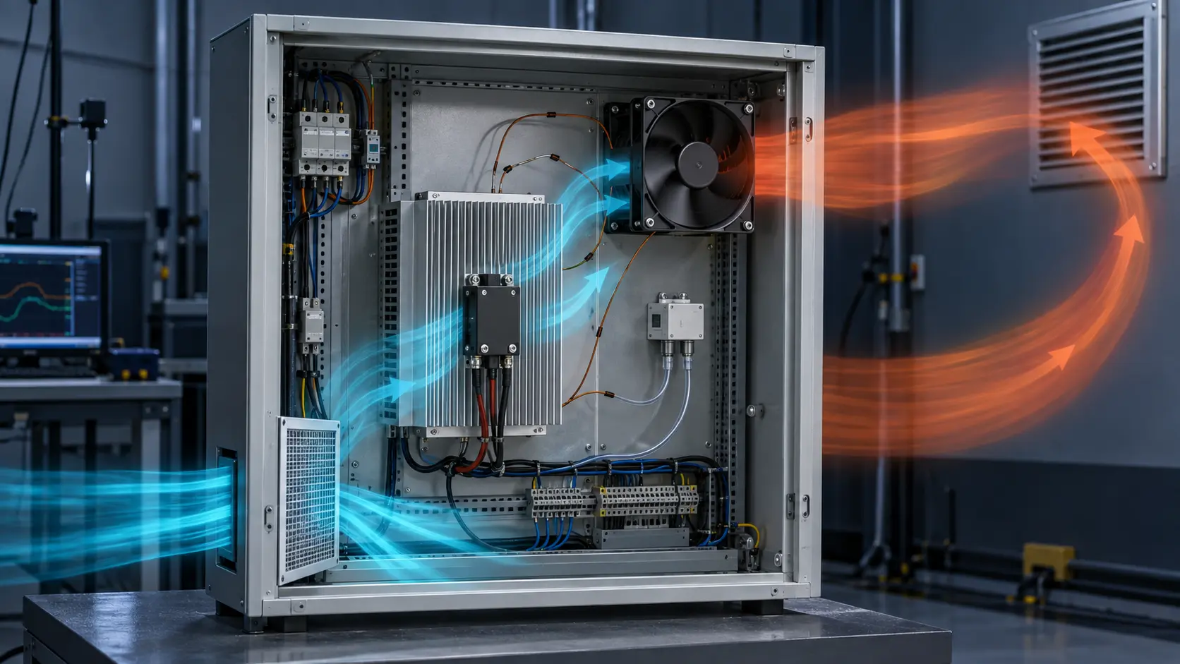
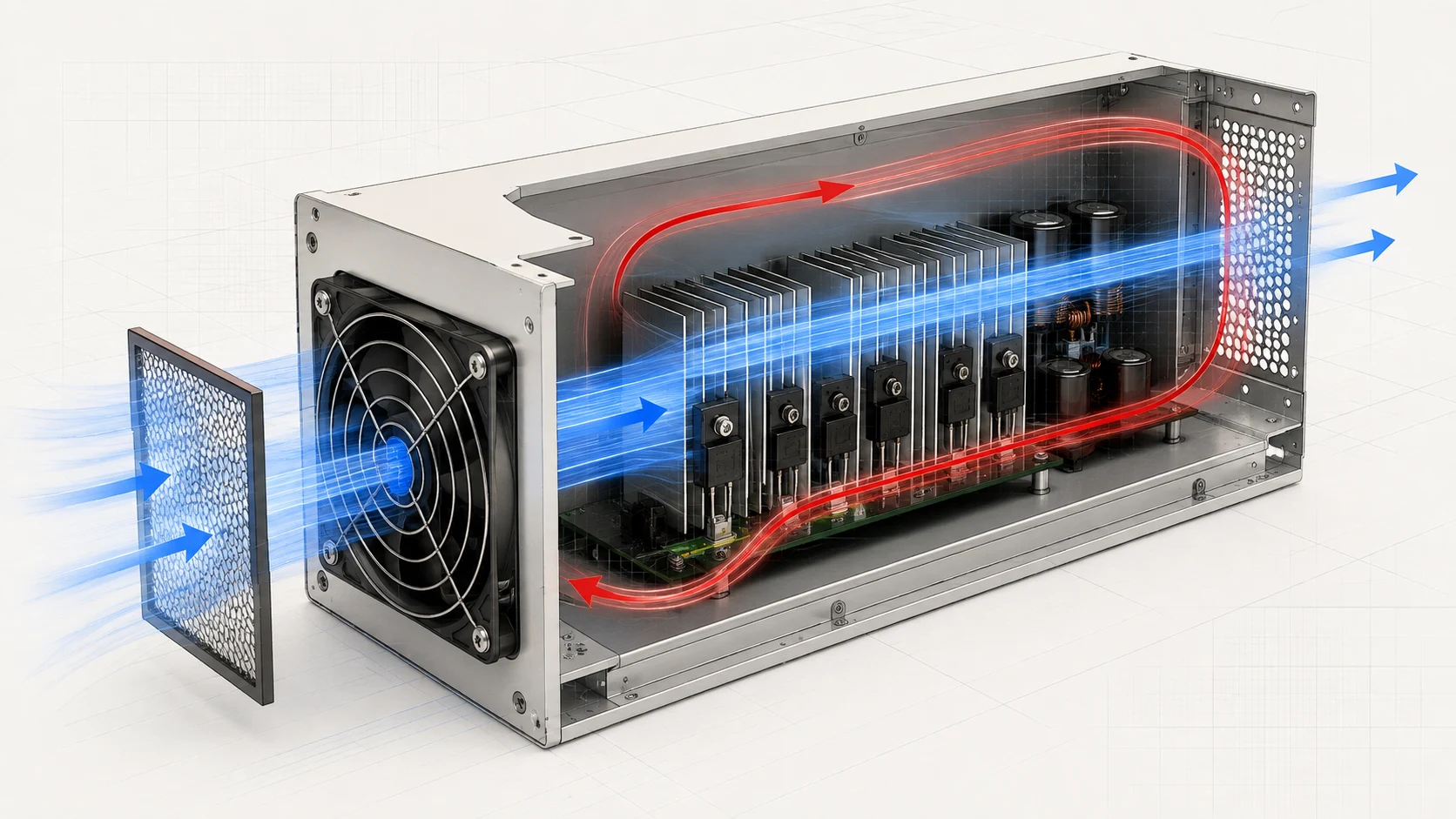
The second half of this pitfall is pressure balance and filtration. Define where make-up air enters and where heated air leaves, then prevent uncontrolled leakage from bypassing the filter or returning to the inlet. The worst case is exhaust air curling straight back into the intake (recirculation), which raises inlet temperature before the air reaches the component.

Pitfall 3–4: Air Short-Circuits the Heat Sink
Air takes the easy route. If an easier route exists beside the heat sink, most of the air takes it.
A fan bolted near a finned heat sink can underperform if air can spill around the fins instead of passing through them. The fix may be a shroud, gasket or baffle that forces the airflow across the fin stack. Without a controlled path, the fan can move a lot of air while the sink stays hot — the classic 'plenty of CFM, still overheating' complaint.
The same shortcut shows up at the rack level. In a battery or drive rack, air that bypasses the modules through a casing gap cools nothing; the modules only balance when airflow is actually forced across them. This is why the static-pressure floor at selection matters: the fan has to overcome the real path, not just spin.

Pitfall 5–6: Choked Inlet and Outlet
A fan needs room to breathe on both sides. Put a wall or a dense grille right against it and you choke the flow.
Mounting a fan immediately against a panel, grille or transition can create non-uniform flow and local contraction as air enters or leaves the fan. The installed performance can fall below the free-air number, while turbulence adds noise and vibration. The correct clearance is not a universal millimetre value: it depends on fan geometry, grille open area, transition shape and the test arrangement.
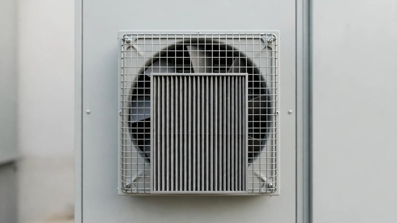
Provide the inlet and outlet space recommended by the fan supplier or validate the restricted assembly directly. Size grilles and guards for the required open area, avoid abrupt transitions, and treat perforated sheet as added system resistance, not free space. AMCA describes these installation losses as system effect: non-uniform or swirling flow near the fan can reduce performance, increase noise and vibration, and force a higher speed. Its example notes that a 10% speed increase can raise energy consumption by about 33%, so adding RPM is not a free correction. When in doubt, read the fan's P-Q curve against the actual restriction rather than the catalogue CFM.
Diagnose the installation before adding fan speed
A measured airflow shortfall is not enough to identify the cause. Define the measurement planes and compare the installation with a controlled reference before changing the fan.
Measure the fan speed, voltage or PWM duty, current, inlet temperature, pressure at defined planes and delivered airflow or velocity distribution. Keep the grille, guard, filter, heat sink, shroud and cable routing unchanged while comparing configurations. A pressure tap in a recirculation zone or a velocity probe too close to a bend can make a good or bad installation look better than it is.
ISO 5802 describes in-situ fan performance measurements, including pressure, velocity, temperature, density and rotational speed, and notes that the measuring station and pressure-plane location matter. ISO/TR 16219:2024 similarly treats system-effect factors as geometry-dependent trends rather than universal correction numbers. Use those principles to design a repeatable comparison, not to apply a generic clearance or loss factor blindly.
If a layout change improves airflow at the same speed, the installation was part of the loss. If the result does not change, revisit the system curve, the fan curve, the restriction data and the measurement uncertainty before increasing RPM. A speed increase can recover flow while increasing power, noise and bearing stress, so it should be the last correction rather than the first.
- Define pressure taps, velocity stations and temperature locations before testing.
- Record speed, voltage or duty, current, airflow and pressure together.
- Compare the installed assembly with a controlled reference at the same duty.
- Treat generic system-effect factors as guidance, not as a universal correction.
- Check noise, power and reliability before solving an airflow shortfall with more RPM.
Worked Example: Why More RPM Is an Expensive Fix
Speed can recover some airflow, but it also changes pressure, power, noise and bearing stress. Treat the fan laws as an estimate, not as a substitute for an installed test.
For the same fan geometry and comparable air conditions, a 10% speed increase is commonly estimated as approximately 10% more airflow, 21% more pressure capability and 33% more aerodynamic power. Those relationships help explain why a small speed change can create a large electrical or acoustic penalty.
The installed result still depends on the system curve, controller limits, motor efficiency, inlet condition and whether the original point is stable. If the restriction is caused by a tight grille, abrupt elbow, bypass path or recirculation, increasing RPM may hide the layout problem while increasing noise and bearing load. First remove avoidable system effect or correct the path, then verify the revised operating point at the customer's real load.
This example uses fan-law estimates under stated assumptions. It is not a universal performance guarantee and is not a MEGA Tech product test result.
- Illustrative 10% speed increase: about +10% airflow, +21% pressure capability and +33% power.
- Check motor, controller, acoustic and bearing limits before increasing speed.
- Re-measure the installed operating point after any speed or geometry change.
Pitfall 7–8: Filter Loading Raises Impedance
A clean filter is one restriction. As it loads with dust, its pressure drop can rise enough to move the operating point out of the original thermal design.
Dust loading is the most overlooked field killer. As a filter loads, its pressure drop rises and the system curve changes. The operating point slides left along the fan curve, airflow can fall, and the device can overheat months after commissioning while the fan is still 'running fine'. The size of the change depends on the media, face velocity, dust and service condition; use the filter's clean and loaded pressure-drop data instead of a universal multiplier.
Design for the dirty state, not only the clean one. Size the fan so the end-of-service filter condition still clears the thermal budget, add a pressure-drop or maintenance trigger where practical, and set the interval for the actual environment. A fan selected only for the clean condition is underspecified once the filter starts loading.
Pitfall 9–10: Fans That Fight, and Hotspots That Stay
Two fans are not automatically twice the cooling, and moving air through the box is not the same as cooling the part.
Parallel fans do not automatically deliver twice the installed airflow. The combined fan curve must be compared with the system curve, and fan spacing, inlet flow and control matching can affect the result. Series fans may increase pressure capability, but only when the system and fan arrangement support it. Use the combined curve or measure the actual assembly rather than multiplying a single-fan catalogue number.
The last pitfall is the quietest: the fan cools the enclosure, but not the component. Averaging a cool box temperature hides a local hotspot the airflow never reaches. Direct the flow at the hot part — duct it, shroud it, or reposition the fan — rather than assuming 'the box has a fan, so it is cooled'.
Use installation findings to develop the right fan sample
When the enclosure exposes a pressure, noise or mounting problem, change the fan configuration with the airflow path instead of compensating with guesswork.
MEGA Tech can use the installation review as the starting point for a customized fan requirement. We look at the actual heat load, grille and filter restriction, duct or shroud, available space, noise limit, voltage, speed range, control signal, feedback, mounting and environment. This prevents the common mistake of forcing a catalogue fan into an enclosure that needs a different pressure or mechanical interface.
The fan can be adjusted for frame size and thickness, airflow and static pressure, speed, PWM, FG or RD feedback, connector and cable length, bearing choice, rotation direction, mounting and protection. For new products or small first builds, we can develop a sample around the representative enclosure, including the real heat sink, grille, filter, baffles and cable routing.
Validation should compare the installed operating point before and after the change: delivered airflow, pressure margin, local component temperature, noise, control response, filter loading and continuous operation. Once the path and fan are approved together, the configuration can move into reliable volume production with a clear installation and replacement baseline.
- Treat installation restrictions as design inputs for the fan specification.
- Customize pressure, size, control, feedback, wiring, bearing and mounting details.
- Test the sample with the actual duct, grille, filter, heat sink and cabling.
- Transfer the validated fan and installation configuration into repeatable production.
Engineer FAQ: Fan Installation, Ducting and System Effect
The fastest way to avoid an installation mistake is to connect every answer to the actual fan, restriction, measurement plane and operating condition.
Q: Is there a universal clearance between a fan and a grille, wall or elbow? A: No. The required clearance depends on fan geometry, inlet/outlet shape, open area, transition and test arrangement. Use the supplier's guidance as a starting point, then validate the complete assembly when the path is compact.
Q: How do I know whether system effect is causing the airflow shortfall? A: Compare the installed result with a controlled reference. Check inlet and outlet velocity distribution, nearby bends or obstructions, pressure-tap locations, grille open area and recirculation. If a geometry change improves the result without changing fan speed, the installation was part of the loss.
Q: Should I seal every gap around a filter? A: Seal the intended frame-to-filter interface, but do not block required pressure-relief or service paths. Even a small bypass can let air avoid the filter and make the measured pressure drop look better while reducing actual filtration and component cooling.
Q: Do two fans in parallel always double airflow? A: No. The combined fan curve still has to intersect the system curve, and inlet interaction, spacing, control mismatch and shared restrictions can reduce the gain. Treat multiplication as an estimate until the array is measured in the actual enclosure.
Q: What should be measured before releasing the installation? A: Record fan voltage, speed or duty, current, airflow, pressure at defined planes, inlet temperature, hotspot temperature, noise and filter condition. Repeat the check with the representative grille, shroud, cable routing and loaded-filter condition where those affect the design.
- Do not convert a catalogue clearance into a universal rule.
- Define pressure taps and airflow measurement planes before comparing results.
- Check filter-frame bypass separately from filter-media pressure drop.
- Validate the complete fan array or duct assembly instead of multiplying single-fan data.
Pre-Power-On Installation Checklist
Walk this list before energizing. It catches every pitfall above in two minutes.
- Flow arrow verified: intake and exhaust point the intended way, not reversed.
- No recirculation loop: exhaust cannot curl back into the intake.
- Deliberate intake and exhaust paths; no reliance on leaks for make-up air.
- Air is ducted or shrouded across every heat sink — no open bypass gap.
- Clearance on both sides of the fan follows the supplier's guidance or has been validated with the actual grille/guard.
- Filter sized and a maintenance interval set for the real environment.
- Fan selected against the DIRTY-filter operating point, with margin.
- Parallel/series fans matched, or performance treated as an estimate.
- Airflow directed at the actual hot component, not just through the box.
- P-Q curve checked against the real system resistance, not free-air CFM.