A switch is a fan system inside a rack airflow system
Network switches cool with several high-static-pressure fans running 24/7 in a rack whose airflow direction is already decided by the data hall. The switch's fans must match that rack-level airflow — a thermally brilliant switch with the wrong airflow direction cooks itself and its neighbours.
Switches concentrate heat in a way few electronics do: a switching ASIC with a dense heatsink, optics lined up along the front face, power supplies sharing the same chassis, and all of it in a 1U or 2U enclosure at the front of a rack that expects air to enter cold and leave hot. The fans are small, fast, high-pressure and always running — which makes them both the thermal solution and the acoustic complaint, the dust collector and the single most common field failure.
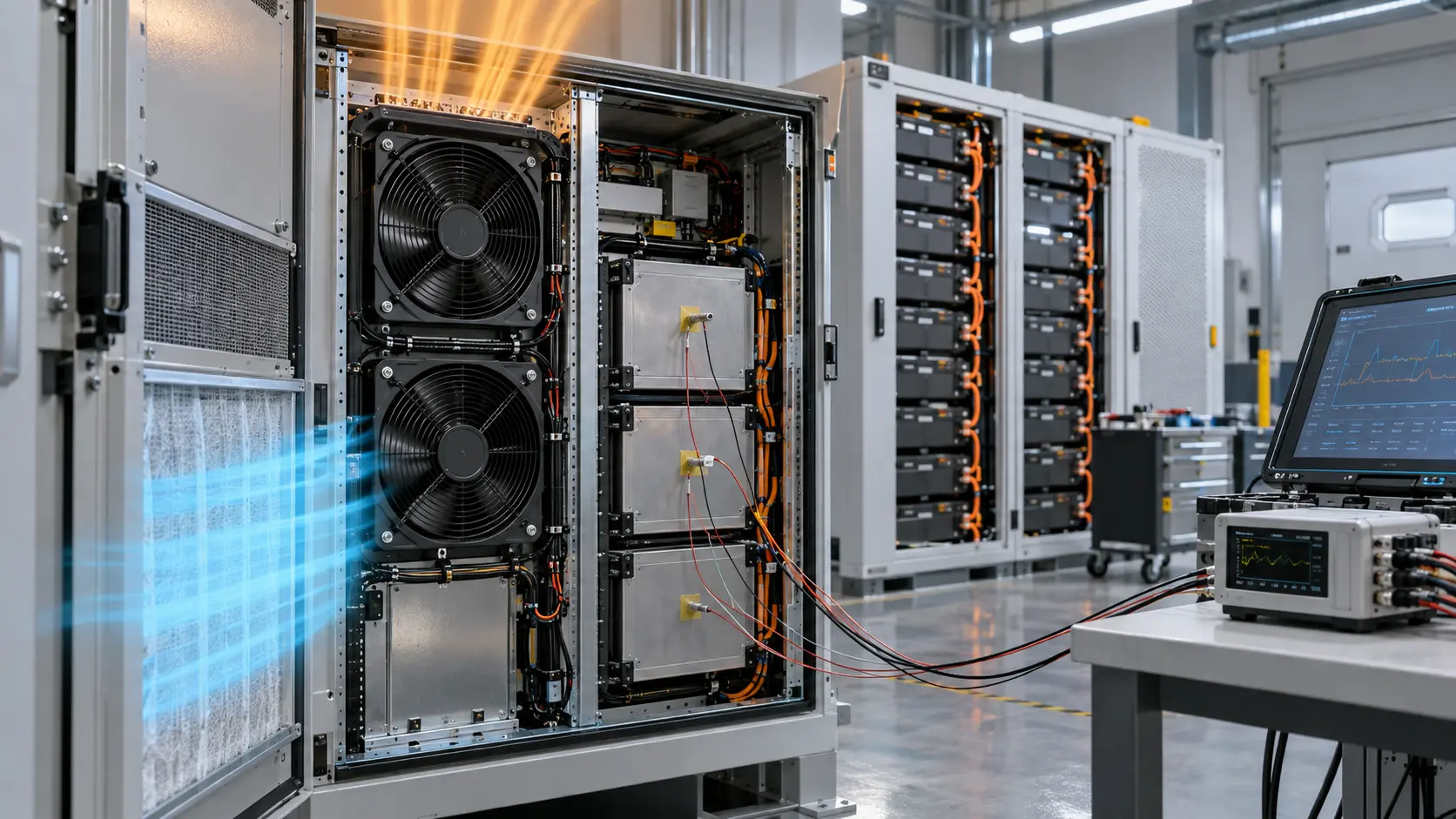
The engineering problem has two layers. Inside the chassis, the fans must push enough air through the ASIC heatsink, the optics cage and the PSU bay at the resistance those paths impose — the same operating point arithmetic as any fan selection. Around the chassis, the airflow direction must match the rack convention so the switch draws from the cold aisle and exhausts to the hot aisle; a reversed or mixed-direction switch recirculates preheated air, and its internal temperatures rise by degrees that no internal sensor will explain.
This guide covers both layers: the rack airflow conventions a switch design must respect, the internal selection of high-pressure fans and their control, the acoustic and dust realities of 24/7 unattended operation, and the validation protocol that proves all of it in the real rack. The fan-level method is shared with the operating point replacement method.
Rack airflow conventions: the direction is decided before the switch is
Data halls are built around front-to-back airflow: cold aisle in, hot aisle out. Every component in the rack — including the switch — must agree with that direction.
The convention exists because the cooling plant — the room's CRAC units, containment and perforated tiles — delivers cold air to one face of the rack and expects hot air at the other. A switch that pulls air from the hot aisle, or worse, that mixes directions internally, rejects its heat into the cold aisle or recirculates it into its own intake. The symptom is a switch that runs hot with no local cause, and optics that fail early in a chassis whose temperatures look nominally fine.
This is why switch hardware carries airflow direction in the product itself: direction labels on the chassis and reversible fan modules ordered by direction code. The design obligation is consistency — fans, PSU airflow and optics all agree with the chassis label, and the label agrees with the rack. A mixed-PSU situation — one airflow direction in a PSU bay that expects another — is a classic assembly error that no firmware will catch.
Where the rack is not the reference — wall-mounted cabinets, office wiring closets, edge cabinets outdoors — the direction convention becomes a design decision instead of a given, and it must be written down with the same discipline: one defined intake face, one defined exhaust face, and every internal component arranged to respect them. The outdoor cabinet environment adds humidity and solar load to the same direction discipline.

Inside the chassis: a high-pressure selection problem
The switch's internal path is dense: ASIC heatsink fins, optics cages, PSU bays and cable bundles in a 1U height. The fans that survive here are high-static-pressure designs matched to the operating point.
The internal selection follows the operating point method exactly. Measure or estimate the resistance of the internal path at the required airflow — dense fin stacks dominate — and cross the candidate fan's curve against it. Small-diameter, high-speed, high-pressure fans are the natural fit; free-air comparisons mislead exactly as they do everywhere else, and a larger slower fan that cannot fit the 1U height is not a candidate at all.
Control is where switches differ from simpler equipment: fan speed is commanded from ASIC and optic temperatures, which means the PWM interface and the duty-to-speed response are part of the thermal design. The controller ramps fans as silicon heats and idles them when traffic is light; the fans must behave predictably across the whole sweep — no hunting at mid duty, no acoustic tone at idle. The PWM control guide covers the interface contract.
Redundancy completes the design: most switch platforms run N+1 fan modules so a failed module does not throttle the ASIC. The redundancy arithmetic and its control implications are covered in the parallel fans and N+1 redundancy guide — the short version is that the N+1 case must hold the full thermal duty at worst case, not merely spin.
| Checkpoint | What to verify | Source |
|---|---|---|
| Operating point | Fan curve crosses the internal path's resistance at the ASIC's required airflow | Measured or estimated path resistance; candidate P-Q data |
| Airflow direction | Fan module direction code matches chassis label and rack convention | Module option code; smoke trace at rack level |
| Control behaviour | Duty-to-speed response inside the thermal controller's assumptions across the sweep | Controller tuning notes; sample measurement |
| Redundancy | N+1 case holds full duty at worst case; failed-fan detection and reporting | Thermal budget at N+1; firmware alarm logic |
| Acoustics | Sound at operator position across the duty sweep, including idle | In-housing measurement |
Acoustics: the office wiring closet problem
A switch that is silent in a data hall can be intolerable in an office closet. Acoustic budgets decide fan speed floors and controller tuning, and they are easier to design for than to retrofit.
Enterprise switches live in two acoustic worlds. In a data hall, equipment noise is ambient and the switch's fans contribute a fraction. In an office wiring closet or a wall cabinet beside a desk, the switch is the only noise source, and the fans' blade-pass tone — from small, fast, high-pressure impellers — carries through a door and a wall. The acoustic limit at the operator position then becomes a design input to the fan selection and the controller's minimum speed, not a post-hoc measurement.
The tools are the same as any quiet design: run the fans at the lowest duty that holds thermal margins, choose high-pressure impellers that do the work at lower speed, and check the duty sweep for tones and hunting — the mid-duty region where some fan-controller combinations hum. The noise measurement guide covers the method; the point that matters for switches is that the acoustic check happens across the controller's real duty range, because the quiet case and the busy case are different machines acoustically.
Where the budget cannot be met with fan selection alone, the design answers are structural: line the closet, route the exhaust away from the work position, or move the acoustic problem into the data hall where it belongs. What does not work is slowing the fans below their thermal duty and hoping the ASIC tolerates it — the thermals were already validated at the lower speeds' absence.
Dust, filters and 24/7 unattended life
Switches run unattended for years in air nobody filtered for them. Dust loading, filter service and endurance are design inputs, not field surprises.
Air moving through a switch for years carries dust into every fin stack and fan bearing zone. As dust loads the path, resistance rises and the operating point moves left — the same loaded-filter effect as any filtered enclosure, but on a machine whose thermal controller will quietly ramp the fans to compensate, spending acoustic budget and fan life to hold temperatures. The design answers are stated early: filter the intake where the environment demands it, size the fan selection at the loaded condition, and set the service interval from the loaded-state pressure rather than the clean one.
Endurance is the second 24/7 reality: fans running at moderate duty for years, with bearing systems selected for the temperature and orientation the switch imposes. The bearing selection guide covers the system choice; the switch-specific point is the service model — fan modules designed for hot-swap replacement turn a bearing end-of-life from a product failure into a maintenance event, and the module's connector, direction code and reporting must all support that swap.
The IP, dust and humidity guide extends this to cabinets where the air itself is humid or corrosive — edge sites, industrial floors, coastal closets — where coating variants and sealed modules join the selection.
Validation in the rack: where the sensors decide
A switch validates in the rack it ships into, at the traffic load and ambient the site actually produces — and the sensor map decides what the validation can even see.
Sensor placement comes first, because a thermal controller can only protect temperatures it measures. The ASIC junction or case sensor, an optics-region sensor, a PSU inlet sensor and an ambient sensor at the intake face cover the map; a chassis whose only meaningful sensor is the ASIC is blind to recirculation, which shows up first in the optics. Where sensors are sparse by design, the validation plan must add temporary instrumentation so the blind spots are measured at least once.
The validation states are three. Nominal traffic at nominal ambient establishes the baseline: fan duty, acoustic level, component temperatures. Worst case — maximum traffic, loaded filters, top-of-rack ambient, and the N+1 fan failure if the platform claims redundancy — must hold the thermal budget with fans at a duty the acoustic limit still tolerates. The loaded and failed states are where selections made on clean, nominal assumptions surface: the controller ramps to a duty that is thermally sufficient but acoustically new, or the N+1 case cannot hold the budget at all.
The rack-level checks complete the picture: smoke trace for direction agreement, intake temperature at the switch face to confirm the switch breathes cold-aisle air rather than a neighbour's exhaust, and the acoustic measurement at the position a human occupies — the closet door, not the rack rear. A switch that passes all of these ships with a thermal behaviour the service team can trust; a switch that passes only the bench has validated a machine nobody actually deployed. The worst-case thermal margin validation guide details the protocol this extends.
| State | Conditions | What must hold |
|---|---|---|
| Nominal | Typical traffic, clean filters, nominal ambient | Baseline duty, acoustics and temperatures recorded |
| Worst case | Max traffic, loaded filters, top-of-rack ambient | Thermal budget held within the acoustic limit |
| N+1 failure | Worst case plus one fan module failed | Full duty held; failure detected and reported |
| Direction check | Smoke or ribbon trace at the rack | No recirculation; cold-aisle intake confirmed |
What MEGA Tech does with switch cooling projects
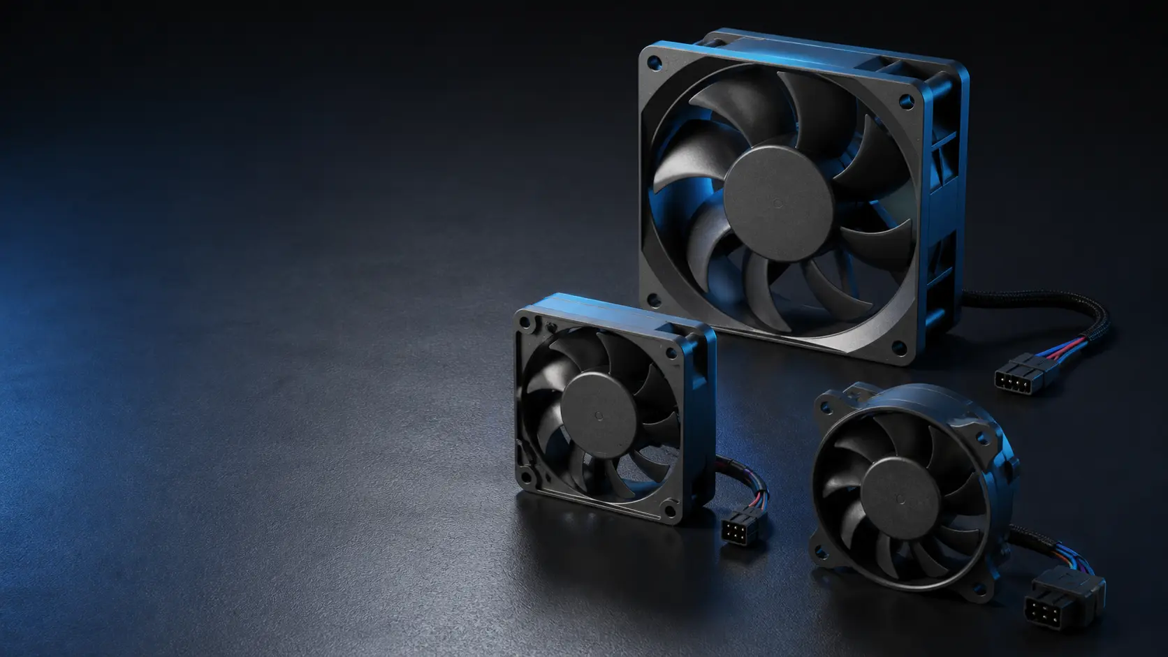
We manufacture the high-static-pressure fans and fan modules that switch platforms run on, and we work with network hardware teams from the operating point arithmetic to the validated module.
What we do: given the chassis path geometry, the ASIC thermal budget and the rack airflow convention, we propose fan modules matched to the internal operating point — direction-coded, with the PWM and tach interface your thermal controller expects, and with measured P-Q and acoustic data for the sample. We support N+1 validation, the loaded-condition selection, and the endurance re-check that a 24/7 product needs before it ships.
What we need from you: the internal path description and thermal budget at worst case, the controller's PWM frequency and duty response assumptions, the rack airflow direction the product must match, the acoustic limit where the product will actually be heard, and the service model — hot-swap module or factory-fit fan.
Where our boundary is: we do not supply switch silicon, chassis sheet metal, cabinet safety design or thermal controllers. Our scope is the fan and fan module — and the measured data that lets your team validate them in the real rack.
Engineer FAQ
The questions engineers actually ask about switch cooling, with the short engineering answers.
Q: The switch runs hot but every component reads within spec. Where is the heat? A: Check the rack-level airflow direction first. A reversed PSU or fan module, or a switch exhausting into the cold aisle, raises internal temperatures through recirculation — the reversed component reads fine while the optics cook.
Q: Why do switches use small fast fans instead of fewer larger ones? A: Height and pressure. A 1U chassis has no room for large impellers, and the dense internal path needs static pressure that small high-speed designs deliver. The cost is acoustic, which the controller manages with duty.
Q: Can I replace a switch's fan modules with quieter third-party ones? A: Only through the full operating point and interface checkpoints — the replacement must match direction code, PWM response, tach reporting and the loaded-condition duty. A quieter fan that crosses the system curve lower will throttle the ASIC under load.
Q: Do we size the fans for clean or dust-loaded filters? A: Loaded. The controller will ramp to compensate as dust accumulates, spending acoustic budget and life; a selection made at the clean condition loses its margins exactly when nobody is watching.
Q: What fails first in a 24/7 switch — fans or PSU fans? A: Both are fans; the first failure is whichever bearing system was mismatched to the temperature and duty. Hot-swap fan modules turn that failure into maintenance rather than downtime, which is why the service model is part of the design.
Q: How is an office closet deployment different from a data hall one? A: Acoustics and environment. The closet makes the switch the only noise source — the duty sweep's tone check decides — and the closet's air quality may demand filtration the data hall never needed.
Questions for a design review
Take these to the review with the chassis path sketch, the ASIC thermal budget and the rack convention on the table.
Switch cooling has two layers, and reviews that check only the internal one produce machines that fail at the rack. These questions close both.
- Does every component's airflow direction — fans, PSUs, optics-side flow — agree with the chassis label, and does the label agree with the target rack convention?
- Has the internal operating point been stated at the loaded, worst-case condition rather than clean?
- Does the N+1 case hold the full thermal duty, and does the firmware detect and report the failed module?
- Does the candidate fan's duty-to-speed response sit inside the thermal controller's assumptions across the whole sweep?
- What is the acoustic limit where the product will actually be heard, and has the sweep been checked for tones at idle and mid duty?
- What is the filter service interval, and is it derived from the loaded-state pressure?
- Is the fan module hot-swappable, and does its option code, direction label and reporting support the service model?