Cooling Control Is Not Emergency Ventilation
A BESS fan-control plan must say what it controls, what it detects and what it must not claim to do.
Normal thermal management uses measured temperatures and a defined control response to keep the intended air path working. DOE separates BMS temperature monitoring and cooling from gas detection and emergency ventilation. That distinction matters: a PWM cooling fan is not, by itself, a fire, gas-management or emergency-ventilation system.
Start with the duty modes that the project actually permits: standby, charge, discharge, high ambient, service restriction, fan fault and controller fault. Each mode needs a named sensor source, command, expected feedback, alarm route and product-level action. A fan vendor can supply a signal interface and application-matched sample; the BESS designer owns the safety architecture and acceptance limits.
Use Sensors That Represent the Cooling Decision
A control loop is only as useful as the temperature and air condition it sees.
A representative BESS control example uses module or rack temperature sensing plus a separate intake-air measurement. The intake reading helps distinguish a warm battery from a warm incoming air stream, and it can reveal when outside air cannot provide useful cooling. Orion BMS documentation illustrates this pattern with thermistors, PWM output and fan-health monitoring; exact sensor count, thresholds and authority remain project-specific.
Avoid controlling from a convenient PCB sensor alone when the acceptance limit belongs to a different module or rack location. Document sensor placement, thermal lag, filtering, hysteresis and the maximum response time that the application needs. Test an unplugged, shifted or implausible sensor value as part of fault handling.
| Signal | Purpose | Evidence to record |
|---|---|---|
| Module or rack thermistor | Thermal demand | Location, temperature, filtering and threshold |
| Intake-air thermistor | Cooling potential / recirculation check | Ambient, intake temperature and installation state |
| PWM command | Requested fan output | Duty, frequency and startup behavior |
| FG / tach | Rotor-speed feedback | Expected RPM range and loss-of-signal handling |
| RD / fault output where available | Fan or driver fault indication | Electrical state, controller interpretation and alarm path |
Interactive Model: Review the Control State
Change temperature, intake condition and feedback state to see what the control plan must record.
This qualitative model is not a BMS configuration or safety controller. It illustrates the questions a review must answer: does the controller request cooling, can intake air help, does feedback agree with the request, and which event must be escalated?
The proposed response always needs a product-specific validation plan. Check fan startup at the lowest permitted command, voltage and temperature, then check the installed airflow path under the stated restriction condition.
Representative Project Scenario: Make the Control Contract Testable
This anonymised scenario shows a realistic engineering workflow, not a published customer result.
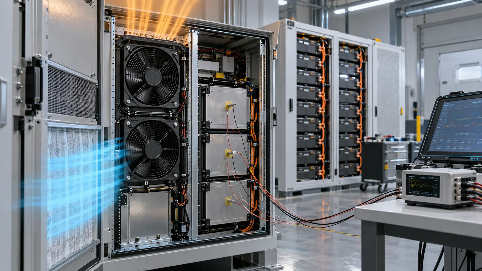
In a representative outdoor BESS cabinet review, an equipment team needed quieter light-load operation without losing visibility of fan degradation. MEGA Tech proposed an application-matched DC axial fan sample with PWM input and FG feedback, plus connector and cable routing matched to the cabinet drawing. The team defined a separate intake thermistor and agreed that a missing or implausible feedback signal would create a maintenance alarm, not silently raise PWM indefinitely.
The sample plan required confirmation of startup, RPM window, current, intake temperature, module hotspot and pressure condition with the final filter and louvre installed. The engineering value was not a universal RPM or temperature number. It was a documented control contract that the BMS, fan sample and test team could all verify before production.
Validate Faults, Not Only the Happy Path
A normal PWM ramp proves little if a stalled, disconnected or restricted fan produces the same controller story.
Test the complete chain: command output, supply voltage at the fan connector, startup, tach or fault feedback, controller interpretation, alarm routing and the resulting thermal response. Include the installed filter, cover, louvre and cable path. A normal FG signal confirms rotation, not necessarily the required airflow through the modules.
For a fan array, define the behavior after one fan is stopped and check whether air returns through the idle fan or bypasses the intended path. Record the remaining fans’ command, RPM, current, relevant differential pressure, intake temperature and named hotspot. Correct geometry and operating point first, then choose the required redundancy or alarm action.
- Normal thermal ramp and hysteresis check.
- Minimum-command and low-voltage startup check.
- FG or fault-feedback loss handling check.
- One-fan-stopped path and hotspot check for an array.
- Clean and agreed service-state filter condition.
- Alarm evidence linked to a documented product action.
Engineer FAQ: BESS Fan Control
The usable output is a transparent interface between the cooling assembly and the BESS control architecture.
Q: Can FG feedback prove BESS cooling airflow? A: No. It proves a rotor-speed signal within an expected range. Confirm installed airflow and hotspot temperature separately.
Q: Should BMS temperature alone command the fan? A: It can be an input, but review intake condition, sensor placement, thermal lag and fault behavior. The selected strategy must match the project architecture.
Q: Is a PWM fan an emergency ventilation device? A: No. Normal cooling, gas detection, emergency ventilation, shutdown and fire response are distinct functions and require their own project controls.
Q: What can MEGA Tech customise for a BESS fan sample? A: We can review airflow and pressure requirement, voltage, PWM/FG/RD interface, connector, cable length, frame, environmental requirement, noise target and validation plan for the intended cabinet.
Q: What is the first test after receiving a custom sample? A: Test startup, command-to-RPM response, current, feedback signal and thermal performance in the representative cabinet with its final airflow restrictions.
Map the complete command and alarm state machine
PWM, FG and RD are interfaces inside a larger state machine. Define the states before choosing thresholds: off, starting, running, warning, fan fault, sensor fault, controller fault and service recovery. For every state, state the command, expected speed evidence, alarm status, timeout and action on the protected load. This prevents a controller from treating an expected start transient as a permanent fault or treating a missing signal as harmless.
Keep the fan-side terms literal in the specification. Identify the PWM reference, frequency range, active level, pull-up arrangement, FG pulse interpretation and RD polarity for the exact fan revision. If the equipment supports multiple fan candidates, do not assume that a wire color or connector shape guarantees the same signal behavior. Sample each candidate with the production controller and harness.
A BESS controller should also record the context around an alarm: rack load, inlet temperature, filter state, fan command, voltage and pressure. That context helps distinguish a fan electrical failure from a system restriction. It also gives service personnel a defensible reason for replacing a fan, cleaning a filter or checking the controller.
| State | Fan command | Required evidence | Action |
|---|---|---|---|
| Start | Defined startup duty | Voltage, current, RPM rise | Allow start window |
| Run | Closed-loop duty | FG/RPM and temperature | Continue or warn |
| Fan fault | Fallback or stop | RD/FG plus path evidence | Alarm and protect load |
| Recovery | Controlled restart | Stable RPM and temperature | Clear only after evidence |
Validate PWM at low speed and under supply variation
A control duty that works in free air may not start a fan against a BESS filter or grille. Test minimum commanded speed with the installed restriction, at the lowest and highest permitted supply voltage and at cold and warm conditions. Record the time to stable rotation, current, pressure or airflow and protected temperature. If the controller applies a kick-start or minimum duty, record those values in the state-machine specification.
Check the PWM waveform at the fan control pin and the DC rail at the same time. A long harness, weak pull-up, ground offset or noisy shared supply can distort the control input without changing the controller’s internal duty value. Use the exact connector and harness length where possible. If the fan is mounted in a redundant array, repeat the test with the neighboring fans operating because shared noise and pressure can alter the result.
Do not use FG alone to prove the operating point. Confirm the installed pressure or airflow and the component temperature. A fan can report a clean pulse train while a filter is loaded or a damper is mispositioned. The controller can use FG as an early diagnostic, but the acceptance record must close the loop with the protected thermal condition.
- Measure PWM at the fan pin, not only at the controller.
- Test minimum duty against the loaded path.
- Include voltage tolerance and harness drop.
- Use pressure/airflow and temperature to close the thermal loop.
Engineer FAQ: PWM, FG and RD alarm logic
Q: Should the controller alarm on one missing FG pulse? A: Usually no; define a debounce and startup window from the exact fan and application trace. A single missing pulse can be noise or measurement error.
Q: Is RD enough to protect a rack? A: RD can provide a defined fan fault signal, but rack protection still needs temperature and air-path evidence.
Q: Why does a fan pass at 100% but fail at low duty? A: Start torque, pressure loading, voltage tolerance and control waveform can make low-duty startup the limiting case.
Q: What should be tested after changing the harness? A: Connector voltage, PWM amplitude and frequency, FG/RD levels, ground reference, start behavior and the loaded operating point.
Q: Who owns the alarm action? A: The equipment designer owns fallback, load reduction, service and recovery logic; the supplier provides fan-side behavior and sample evidence.