Choose technology by cooling layer
EC and AC describe different motor and control approaches; neither label replaces a system specification. The appropriate choice depends on where the fan sits in the cooling architecture, the electrical supply, the required control precision, the operating profile and the maintenance model.
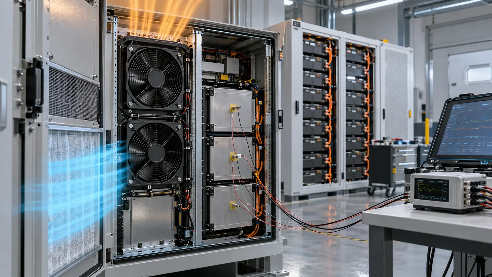
At the facility or large air-moving layer, EC technology may be attractive when demand varies and integrated speed control can reduce unnecessary airflow. Inside compact servers, power supplies and electronics, low-voltage DC fan assemblies are more typical. The engineering boundary matters: a CRAH or fan array and a 12 V or 24 V equipment fan are different design problems.
- Define whether the fan serves facility air movement, a rack subsystem or electronics inside equipment.
- Document available supply voltage, protection and control interfaces.
- Separate room-level cooling requirements from enclosure-level fan requirements.
How EC and AC control differs
A conventional AC fan may be a practical fit for simple, steady-duty operation when its supply, speed and control method match the application. An EC fan normally integrates electronic commutation and speed-control electronics, making it easier to implement demand-based airflow control, but it still needs compatible commands, sensors, protection and fault handling.
The benefit is conditional, not automatic. A variable-speed fan operated at maximum speed most of the time will not deliver the same energy benefit as one controlled against actual temperature, pressure or airflow demand. Input power, controller losses, EMC behavior and restart logic must be checked as part of the complete assembly.
- Confirm the required speed-control range, command signal and restart behavior.
- Review fan behavior after power restoration and control-signal loss.
- Check EMC, input protection and environmental limits for integrated electronics.
- Specify how speed feedback, alarm status and loss of airflow will be monitored.
Compare efficiency at the real duty point
Efficiency should be evaluated at the expected operating points, not only at a catalogue headline. A system that spends much of its life at partial thermal load may benefit from controllable airflow, while a constant-duty application may value simplicity, predictable performance and easier service.
Compare airflow, pressure and total input power at the same system operating point. Include the fan, integrated electronics or external drive, sensors and any relevant conversion losses. A fan that looks efficient in free air may not be the best option after it is installed behind coils, filters or restrictive equipment.
Fan affinity relationships explain why speed control can have a large effect on power, but they are not a promise of fixed savings. The actual result depends on the system curve, control sequence, density, operating hours and the fan's efficiency at each point. Treat any percentage as an engineering estimate to be verified, not a universal EC versus AC rule.

- Use realistic duty cycles and control sequences when comparing annual power.
- Evaluate combined fan, control and system pressure losses.
- Compare input power at matched airflow and pressure, not only at matched RPM.
- Do not compare technologies solely by motor category or free-air maximums.
Power Quality, EMC and Fault Behavior Are Part of the Choice
An integrated electronic fan can simplify speed control, but it also becomes an electrical load that must fit the site's power-quality and fault-management design.
For an EC fan or an AC fan with an electronic drive, check input current waveform, inrush, conducted and radiated emissions, immunity, grounding, protection and restart behavior at the actual supply. The applicable limits depend on the product, installation and market; do not treat a motor label as proof of EMC compliance.
Define what happens when the command signal is lost, the sensor fails, the supply dips or power returns after an interruption. A safe response might be a documented fallback speed, a fault output, controlled restart or a coordinated shutdown, but the correct choice depends on the thermal risk and system redundancy.
For compact low-voltage DC fans, include the upstream AC-DC or DC-DC conversion in the wire-to-air comparison. The fan's own input power can look attractive while the system still loses energy or reliability in the converter, wiring, controller or protection stage.
- Check input, inrush, EMC, immunity, grounding and protection at the intended supply.
- Define PWM, analogue, bus or drive-command loss behavior and restart timing.
- Specify tachometer, alarm or status feedback and the controller response.
- Include conversion and distribution losses for low-voltage DC equipment fans.
Worked Example: Compare Wire-to-Air Power
A matched operating-point calculation is more useful than saying one motor category is efficient and another is not.
Consider an illustrative requirement of 500 CFM at 150 Pa system pressure. The airflow is about 0.236 m³/s, so the air power is Q × ΔP ≈ 35 W. If one complete fan-and-drive arrangement achieves 30% wire-to-air efficiency at this point, its input power would be about 118 W. At 22% wire-to-air efficiency, the input power would be about 161 W.
The example does not claim that EC always reaches 30% or AC always reaches 22%. It shows what must be compared: the complete electrical input at the same airflow, pressure, density, control state and operating time. A variable-speed system may reduce annual energy when the load profile allows it, but the control strategy and actual duty cycle determine the result.
For compact equipment, use the same logic with the low-voltage DC fan assembly. Include the motor electronics, controller, sensor power and conversion losses that the product actually uses. Then confirm the thermal and acoustic result in the representative enclosure.
- 500 CFM = approximately 0.236 m³/s.
- At 150 Pa, air power is approximately 35 W.
- 30% complete-system efficiency: approximately 118 W input.
- 22% complete-system efficiency: approximately 161 W input.
- All values are illustrative estimates, not MEGA Tech test results.
Consider serviceability and system reliability
Data-center equipment is maintained under different constraints from a small enclosed device. Fan accessibility, monitoring, replacement procedure and redundancy should be considered alongside initial performance.
For any technology, the system should identify loss of airflow before component temperatures reach a damaging level. This often requires a combination of tachometer or status signals, temperature sensing and well-defined alarm thresholds.
- Define the response to a fan failure or blocked airflow condition.
- Ensure service personnel can identify airflow direction and replacement requirements.
- Test the remaining cooling capacity when one fan or one control channel is unavailable.
Where compact DC fans fit
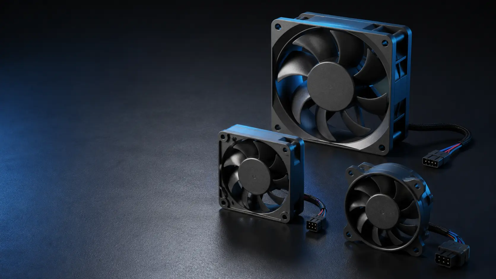
Compact DC axial fans remain central to cooling inside servers, power systems and electronics enclosures. They are selected around form factor, voltage, pressure curve, airflow, noise, tachometer feedback and PWM control, which are different constraints from large air-moving equipment.
A data-center design can therefore include several fan technologies at different layers. The correct approach is to define the cooling duty of each layer clearly and avoid assuming one technology serves every location. For MEGA Tech's equipment-level work, the key comparison is usually the installed low-voltage DC fan assembly, not a direct substitution for a facility CRAH or EC air handler.
- Use the fan curve and enclosure resistance for compact equipment selection.
- Confirm electrical interface and monitoring requirements for each fan bank.
- Discuss custom connector, lead or control needs early when the enclosure is constrained.
- Keep facility-level and equipment-level performance specifications separate.
Engineer FAQ: EC, AC and DC Fan Selection
Use these questions to keep the technology decision tied to the actual cooling layer and operating point.
Q: Is EC always more efficient than AC? A: No. Compare complete input power at the same airflow, pressure, density and duty cycle, including drive and control losses.
Q: Can an EC fan replace a compact DC equipment fan directly? A: Not automatically. Facility or rack-level EC equipment and low-voltage DC fans inside electronics have different voltage, size, pressure, control and safety requirements.
Q: What is the best comparison point? A: The expected operating point and the important part-load points, not only free delivery or maximum pressure.
Q: Is FEI the same as annual energy consumption? A: No. FEI is a standardized duty-point comparison that includes the fan, motor and drive. Annual energy still depends on the system curve, control sequence, operating hours and load profile.
Q: What should happen if the EC command or communication signal is lost? A: Define the documented fallback, alarm, restart timing and thermal protection. Do not assume every integrated controller has the same default behavior.
Q: What should happen if one fan fails? A: Define the alarm, speed response, remaining cooling capacity and thermal protection. Redundancy must be checked at the actual system resistance.
Q: What should be included in an energy comparison? A: Fan, motor, drive, controller, sensors, conversion losses, control sequence, operating hours, system pressure and air density.
Q: When is a custom DC sample useful? A: When the product needs a particular frame, pressure, noise, PWM/FG/RD interface, connector or small first build that standard parts cannot satisfy together.
- Technology labels do not replace a duty point.
- Facility-level and equipment-level fans are different design problems.
- FEI supports duty-point comparison; it does not predict annual savings by itself.
- Compare power, EMC and reliability under the same system conditions.
- Validate the chosen configuration in the representative product.
Turn the technology choice into a tested fan configuration
EC versus AC is only the first decision; the final fan still has to match the customer's enclosure, air path, controls and production plan.
MEGA Tech helps product teams define the compact DC fan requirement inside servers, power systems and electronics equipment. We review heat load, airflow path, pressure loss, available space, noise target, voltage, speed range, control signal, feedback, service conditions and environmental exposure before recommending a configuration.
The fan can be customized around frame size and thickness, airflow and static pressure, PWM or other control, FG or RD feedback, connector and cable length, bearing choice, rotation direction, mounting and protection requirements. For new equipment or early-stage projects, we can develop a sample around the representative enclosure and verify that the chosen technology delivers useful performance at the actual operating point.
Validation should compare normal and restricted airflow, speed response, fault feedback, temperature rise, noise and continuous operation. Once the customer approves the configuration, it can move into reliable volume production, giving the product team a repeatable alternative to expensive imported fan assemblies without confusing a compact DC requirement with a facility-scale EC system.
- Define the cooling layer, heat load, pressure, controls and service target.
- Customize the fan's mechanical, electrical, control and monitoring details.
- Test the sample at the real operating point and under representative restrictions.
- Transfer the approved configuration into stable, repeatable production.
Technology selection checklist
The selection should be documented as a system decision: cooling location, operating profile, controls, performance at pressure, total input power, reliability response and service process. This gives product and facility teams a shared basis for comparing options without treating EC or AC as a shortcut.
- Cooling layer and heat-removal duty are clearly defined.
- Supply, controls, protection and monitoring are compatible with the selected technology.
- Performance and total input power are compared at realistic airflow and static pressure.
- Failure response, EMC and maintenance requirements are included in validation.
- The selected fan is tested in the representative product before volume production.