One Enclosure Can Contain Different Air Systems
Normal thermal control, gas detection and emergency ventilation may share an enclosure, but they do not share the same engineering purpose.
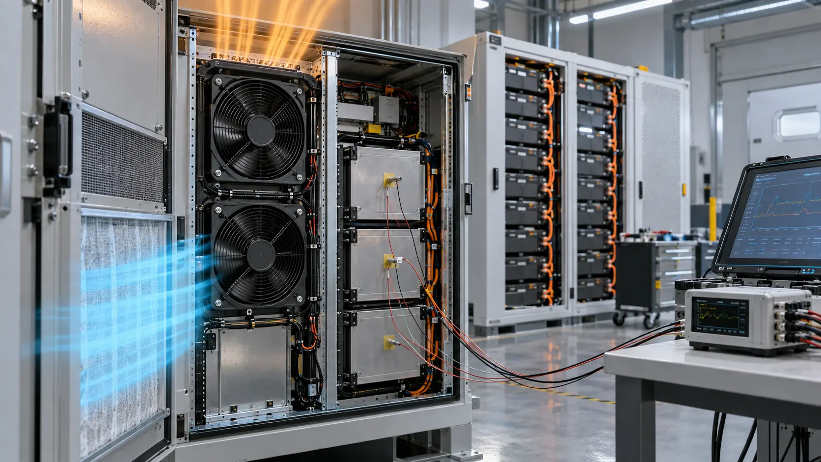
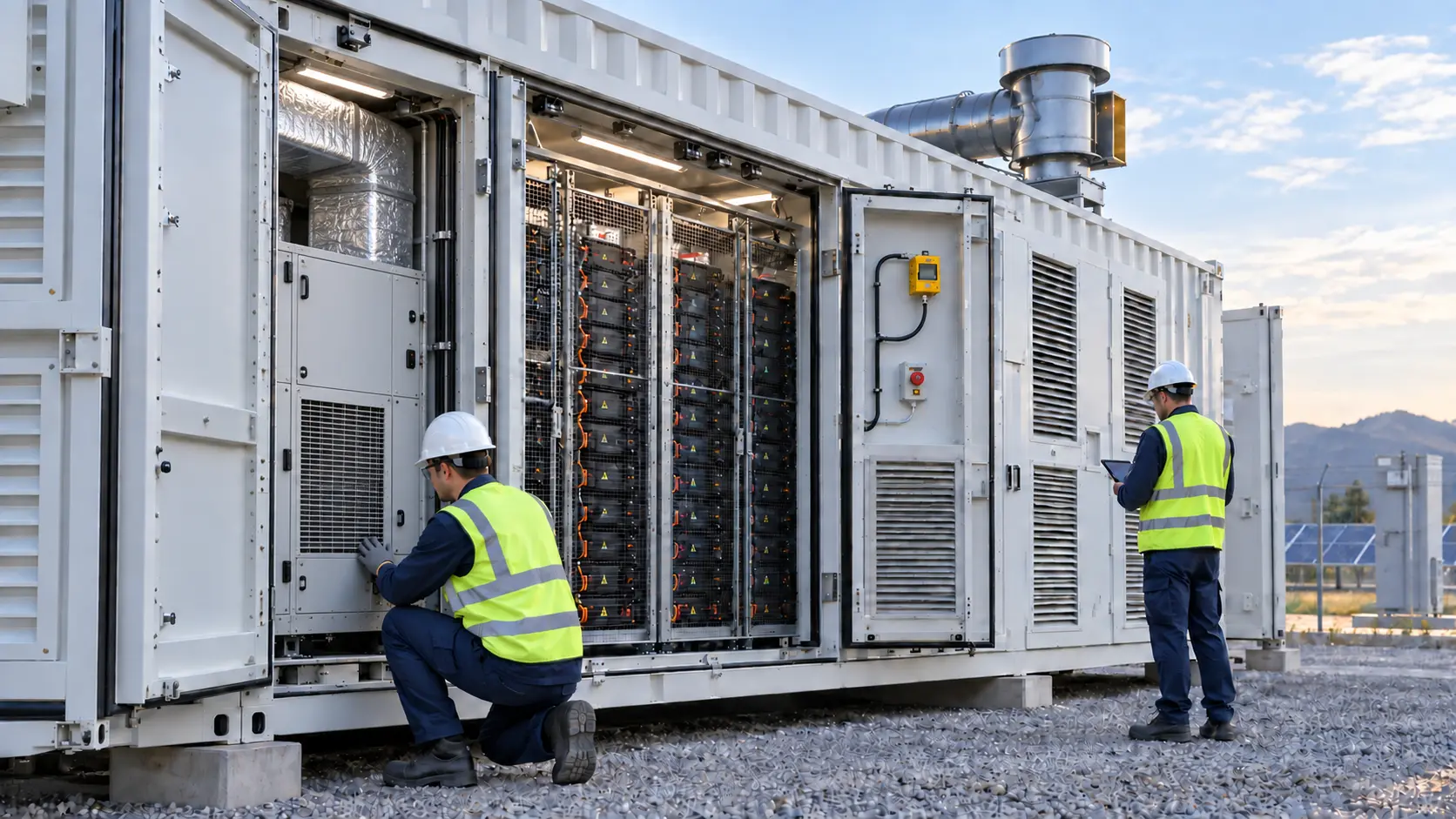
In a containerized BESS, normal thermal management commonly uses HVAC equipment, internal blowers and supply/return ducts to hold battery modules within their intended operating envelope. A cooling fan supplier can support the normal air path through fan selection, control interface, wiring and installed performance validation.
DOE identifies cooling, gas detection and emergency ventilation as separate barriers with different functions. Do not describe a PWM cooling fan as a gas-management, explosion-prevention or fire-safety device. Those functions require project-specific safety design, applicable approvals and validation by qualified parties.
Define the Normal Cooling Contract
The useful fan specification begins with the installed thermal path, not a catalogue airflow number.
For an HVAC or cabinet air path, define heat load, ambient range, supply and return geometry, filter and louvre losses, available space, voltage, control signal, noise, service interval and acceptance temperatures. Select the blower or axial fan at the actual system operating point, then verify the completed air path with the intended covers and restrictions.
Record command, voltage, RPM or feedback, current, relevant pressure, supply temperature, return temperature and named battery-module or electronics hotspot. This evidence links a custom fan sample to a real cooling decision instead of treating free-air CFM as proof of installed performance.
| Function | Typical evidence | Fan supplier role |
|---|---|---|
| Normal thermal management | Temperatures, pressure, command and installed airflow | Fan selection, interface and sample validation |
| Gas detection | Detector selection, placement, response and maintenance | Provide physical integration data when requested |
| Emergency ventilation | Safety design, interlocks, testing and approvals | Do not substitute normal cooling fan claims |
Interactive Model: Keep the Functions Separate
Select each subsystem to see why one normal-cooling result cannot close a safety-design question.
This schematic is a communication model, not a safety-logic diagram. It helps an engineering team assign each signal and air path to the appropriate owner before selecting a fan sample.
Representative Integration Scenario
This anonymised scenario describes a practical sample review, not a customer result.
A representative integrator needed a replacement blower for a BESS HVAC air-handling module and asked whether the same fan could be treated as the container emergency exhaust device. The review separated the jobs. MEGA Tech matched the normal thermal-duty operating point, connector, cable length, PWM/feedback interface and service space for the HVAC module; the integrator retained ownership of the separate safety exhaust and detection architecture.
The sample validation checked startup, command response, current, feedback, pressure and supply/return temperatures with the module installed. It did not claim gas dilution, emergency response or certification performance.
Engineer FAQ: BESS Air-System Boundaries
Clear function boundaries make the fan specification more credible and easier to validate.
Q: Can a normal cooling fan be specified as emergency ventilation? A: Not by assumption. Emergency ventilation is a separate project safety function with its own design, controls and approvals.
Q: What should be provided for an HVAC fan sample? A: Share heat load, system pressure, temperature range, geometry, voltage, control, feedback, connector, noise and service requirements.
Q: Does a normal RPM signal prove cooling? A: No. Validate the installed pressure path and temperatures as well.
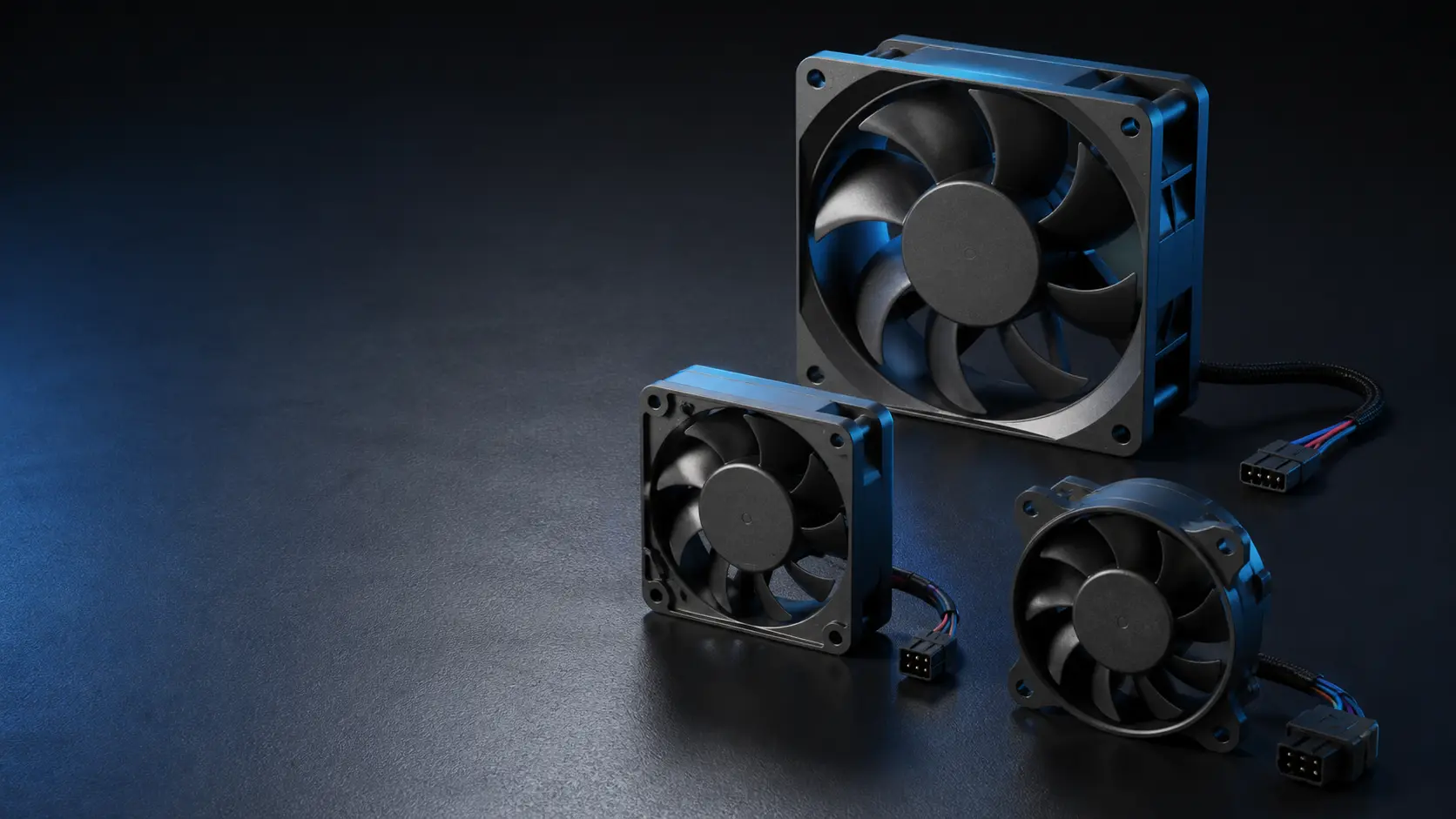
Q: Can MEGA Tech customise the fan interface? A: Yes. We can review frame, airflow/pressure duty, PWM/FG/RD signals, cable, connector and sample validation for the normal cooling assembly.
Define the boundary between cooling and emergency ventilation
Normal cooling keeps the battery enclosure, electronics and auxiliary components inside their operating envelope during expected load. Emergency ventilation is a protective function with a different trigger, airflow objective and risk assessment. A normal cooling fan should not be described as an emergency extraction system unless the complete equipment design, controls, power path and applicable safety requirements have been reviewed for that purpose.
Write the boundary into the functional specification. Identify which fan is allowed to run continuously, which signal requests a higher duty, which independent sensor creates an alarm, and what happens if the cooling fan, controller or supply is unavailable. If the emergency function requires a separate path, keep that path physically and logically distinguishable from ordinary heat rejection. This avoids an ambiguous “fan on” state that cannot tell an operator whether the system is cooling normally or responding to a hazard.
For supplier discussions, provide the normal heat load, air path, pressure loss, temperature envelope, control interface and duty cycle. Keep emergency assumptions in the equipment safety file. MEGA Tech can discuss fan-side airflow, pressure, control and sample validation, but it does not replace the system designer’s safety case or emergency ventilation design.
| Question | Normal cooling | Emergency function |
|---|---|---|
| Purpose | Remove expected heat | Respond to a defined abnormal condition |
| Trigger | Load, temperature or control command | Independent alarm or safety logic as specified |
| Evidence | Airflow/pressure and component temperature | Detection, safe state, availability and recovery evidence |
| Ownership | Thermal/mechanical design team | Equipment safety and compliance team |
Validate the loaded air path at the normal duty
A BESS enclosure can look acceptable at no-load or with a clean filter while the installed system fails after dust loading, recirculation or a changed damper position. Measure the fan at the pressure created by the actual grille, filter, heat exchanger or duct. If the system has more than one compartment, map the inlet and outlet temperatures separately; an average enclosure temperature can hide a local battery or electronics hot zone.
Use at least three operating states: minimum continuous load, representative normal load and the highest expected normal load. At each state record command, connector voltage, RPM, airflow or differential pressure, inlet temperature, protected component temperature and noise if relevant. Repeat after the filter reaches the defined service condition. The goal is to establish a normal cooling envelope before an emergency signal is ever considered.
If the required operating point is not known, do not select by free-air CFM alone. Estimate or measure the pressure drop of every restriction, then compare the fan curve and system curve. A fan with a higher free-air number may deliver less useful airflow at the installed pressure than a candidate with a more suitable pressure curve.
- Label every pressure tap and temperature probe in the test record.
- Repeat the test with representative cable and filter installation.
- Separate normal thermal acceptance from emergency response acceptance.
- Document the service condition that triggers filter maintenance.
Test degraded states and recovery without inventing a safety claim
A practical degraded-state test can include a blocked or loaded filter simulator, a failed fan signal, a lost command, a supply interruption and a sensor out-of-range condition. The exact test sequence belongs to the equipment risk analysis. What matters is that the controller response is observable: which alarm appears, which fan or path remains available, whether the load is reduced, and how recovery is confirmed.
For N+1 arrangements, isolate the failed path if the enclosure permits reverse flow. Then compare the surviving fans’ pressure, airflow and temperature against the same operating state before the failure. If a failed fan becomes a low-resistance opening, the surviving fans may move air through the opening instead of through the battery or electronics. The test must therefore include the physical failure state, not only a software flag.
Record the result as a project-specific verification, not a universal guarantee. A supplier can provide sample data for the selected fan and interface. The equipment manufacturer must decide whether the combined design meets its thermal, functional-safety and service requirements.
Engineer FAQ: BESS cooling and emergency states
Q: Can one fan perform both functions? A: Only if the complete equipment design and applicable safety analysis support that architecture. Do not infer emergency capability from a normal cooling datasheet.
Q: What is the most useful supplier input? A: Fan curve at the required voltage, control and feedback behavior, temperature limits, sample results and the mounting/air-path assumptions used for the test.
Q: Why test a loaded filter? A: Filter pressure changes the operating point. A fan can retain speed while delivered airflow falls, so the loaded condition must be measured.
Q: What should happen after a failed fan? A: The equipment specification should define detection, fallback, load reduction, alarm, service action and recovery confirmation. The fan supplier cannot choose those system actions.
Q: Is a higher CFM fan automatically safer? A: No. Pressure, recirculation, noise, power, control stability and the real operating point all matter.
Document assumptions for review and service
A BESS cooling record should list the assumptions that can change after installation: filter class and service state, enclosure orientation, fan spacing, inlet temperature basis, altitude, humidity, cable length, control mode and available supply voltage. These assumptions are part of the operating point. If one changes, the responsible engineer should know which test must be repeated instead of treating the original sample result as a permanent blanket approval.
Make the service instruction observable. Identify the pressure or temperature indication that calls for inspection, the expected fan signal during normal cooling, and the evidence needed to clear the alarm. Keep emergency and normal-cooling records linked but separate, because they answer different questions and may have different owners. This structure also helps a supplier respond to an inquiry with the exact airflow, pressure, voltage and environmental information needed for a useful sample discussion.