How to Select a Cooling Fan: Start with the System, Not Max CFM
The right cooling fan is the one that delivers the required airflow at your product's real system resistance, within its mechanical, electrical, acoustic and service-life limits. Selection should end with a tested sample, not just a model number.
Engineering a thermal solution starts by defining the problem, not by browsing fan models. A high-CFM fan in free air will underperform if the system impedance chokes its airflow, just as an oversized fan can waste power and generate unacceptable noise. The AMCA guide to fan curves likewise treats fan performance and system resistance as one selection problem.
To arrive at the correct cooling fan, follow this universal engineering workflow:
Application Requirements → Physical Envelope (Size & Thickness) → Supply Voltage → Required Airflow (CFM) → System Static Pressure → Acoustic Budget → Control & Signal Interface → Operating Environment & Lifetime → Fan Model Selection.
- Never choose a fan by looking at free-air CFM alone.
- Always evaluate the enclosure or heatsink resistance before picking a curve.
- Balance thermal performance against acoustic and electrical constraints early in the design.
Step 1: Define the Physical Envelope
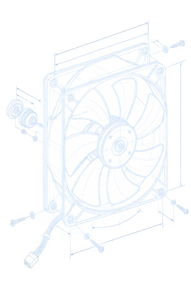
Your mechanical housing sets the hard boundaries for fan dimensions, mounting pitch and thickness.
Axial and centrifugal fans come in standardized frame sizes—ranging from compact 25×25mm and 40×40mm blowers for dense electronics, through standard 80mm, 92mm and 120mm server fans, up to high-output 172×150mm and 200mm industrial units.
Thickness matters as much as face dimensions. A 38mm-thick fan (such as a 12038 or 9238 format) may provide more blade depth and pressure capability than a 25mm slim version, but thickness alone is not a performance guarantee: compare the measured static-pressure curve at the required operating point.
Always verify airflow direction (rotor rotation and exhaust side) and check for wire harness clearance within the enclosure.
- Match the enclosure cutout and mounting hole spacing exactly.
- Consider thicker fans (e.g., 38mm) when the measured pressure requirement and envelope allow it; verify the curve rather than assuming thickness guarantees pressure.
- Confirm whether intake or exhaust orientation suits your internal thermal path.
Step 2: Confirm Voltage and Electrical Supply
The electrical architecture dictates your fan motor class and available input range.
Direct Current (DC) brushless fans dominate modern electronics, telecommunication racks and server hardware, operating typically on standard rails of 12V, 24V or 48V. High-voltage DC (HVDC) or 48V systems are increasingly favored in modern AI data centers and BESS containers for distribution efficiency.
Alternating Current (AC) fans remain common in legacy HVAC, heavy industrial machinery and high-voltage power distribution cabinets operating directly on 115V or 230V AC mains.
Ensure your power supply can handle the startup surge current (inrush current). The peak and duration depend on the fan motor, driver, load, supply impedance and control method, so do not apply a universal multiplier; use the selected fan's measured or specified startup data.
- Match the fan rated voltage to your system bus (12V, 24V, 48V DC, or AC mains).
- Check operating voltage ranges to ensure stable performance during bus voltage dips.
- Account for startup inrush current in your power supply design.
Step 3: Calculate Required Airflow (CFM)
Translate your total thermal load (watts) and allowable temperature rise into a volumetric airflow target.
The fundamental goal of a fan is to transport thermal energy away from heat-generating components. The required airflow depends on the heat that actually enters the cooled air path and the permissible air temperature rise (Delta T) between representative inlet and outlet measurement locations.
Do not automatically substitute total electrical input, processor TDP or component-to-ambient temperature for the heat-to-air boundary. Some energy may leave through conduction, radiation or another cooling loop. For a first estimate, sensible heat removal follows Qv = P_heat / (rho x cp x Delta T), with units kept consistent. This is only a starting airflow: real-world flow rates must account for internal obstacles, bypass leakage, component density and the actual system resistance.
For a deeper dive into volumetric calculations and derating rules, see Understanding Airflow (CFM).
Worked Example: From Heat Load to a Fan Specification
A useful fan request contains a duty point and the conditions around it, not only a frame size and a maximum CFM value.
Consider a 300 W electronics enclosure with an allowable air temperature rise of 12 °C. At a near-room-temperature reference density, the first heat-balance estimate is about 44 CFM. If the fan must operate at 2.0 mmH₂O system resistance, the selection target is not a 44 CFM fan; it is a fan that can deliver approximately 44 CFM at 2.0 mmH₂O at the specified voltage and speed.
The engineer should then add the real conditions: maximum fan-inlet temperature, filter loading, grille and heatsink resistance, minimum supply voltage, noise limit, control range and required service life. The final selection may need a different size, speed or fan type even when the free-air CFM looks similar.
This example is an engineering estimate, not a MEGA Tech test result. A sample must be tested in the representative enclosure to confirm delivered airflow, pressure, temperature, noise, current and control response.
- 300 W heat load and 12 °C rise: approximately 44 CFM first-pass target.
- Required operating point: approximately 44 CFM at 2.0 mmH₂O, not 44 CFM at free air.
- Recheck at maximum inlet temperature, loaded filter and minimum voltage.
- Verify the selected sample in the actual airflow path before BOM release.
Step 4: Evaluate System Static Pressure
A fan does not operate in free air; it pushes against the hydraulic resistance of your entire enclosure.
Filters, dense aluminum heat sinks, tight cable bundles, perforated grills and crowded PCB layouts all create flow resistance. As static pressure rises, actual delivery drops below the catalog headline CFM.
You must evaluate where your operating point sits on the fan's P-Q curve when installed in the actual hardware assembly.
Also document whether the requirement uses fan static pressure or total pressure. The two are not interchangeable when outlet velocity is significant, and installation effects at the inlet or outlet can add losses that are not visible in a standardized catalogue test. Keep the pressure definition, measurement location and installation condition together with the target airflow.
Use the interactive tool below to see how fan speed and system resistance set the real operating point. Drag the sliders: raising System Resistance moves the operating point left (less airflow), while raising Fan Speed lifts the fan curve so the point moves up and right (more airflow at higher pressure).
For a complete explanation of system impedance and pressure curves, see Static Pressure Explained and Reading a P-Q Curve.
Step 5: Set an Acoustic and Noise Budget
Acoustic output (measured in dBA) is often the primary constraint in medical devices, office equipment and quiet server rooms.
Fan noise changes with rotational speed, blade tip velocity, installation and the surrounding enclosure. A larger fan running at lower RPM can be quieter for the same delivered airflow, but the result must be measured in the intended assembly rather than assumed from frame size alone.
Establish an acceptable dBA threshold early in the mechanical design phase, and define the measurement method, operating point, installation and receiver position. Multiple fans can raise the combined level, but the increase depends on source correlation, spacing, room reflections and the measurement setup; it is not a universal fixed addition.
- Prioritize larger diameter fans at lower RPM for noise-sensitive environments.
- Use PWM speed control to quiet fans during idle or low thermal load periods.
- Measure noise using the specified acoustic method and a documented receiver position; do not compare numbers from different distances, rooms, installation categories or operating points as if they were equivalent.
Step 6: Choose Control and Monitoring Interfaces
Modern thermal management requires dynamic speed adjustment and real-time failure detection.
Basic 2-wire fans offer simple power and ground, running at full speed continuously. Adding a 3rd wire provides Frequency Generator (FG) or tachometer feedback to monitor RPM and detect stalled rotors.
A 4-wire PWM interface adds precise duty-cycle speed control, allowing your system controller to ramp airflow up or down based on real-time temperature sensor telemetry.
For details on pinouts, tachometer pulses and control curves, see PWM & Speed Control.
Step 7: Match Environment and Bearing Life
Continuous 24/7 operation demands bearing selections and ingress protection suited to the operating environment.
Operating temperature, mounting orientation, dust levels and moisture exposure help determine whether a sleeve, hydraulic or ball-bearing configuration is suitable. The allowable orientation is a property of the selected bearing and fan design, not a universal rule for an entire bearing family.
L10 bearing life ratings describe a 90% survival point under stated test conditions. Elevated internal temperatures can materially shorten grease life, but the correction is model- and lubricant-dependent rather than a universal exponent.
For a detailed comparison of bearing mechanisms and reliability metrics, see Fan Lifetime & Bearings.
From selection requirements to a production-ready sample
A fan-selection checklist becomes valuable when it leads to a configuration tested in the customer's product, not just a model number on a spreadsheet.
MEGA Tech can support the selection process from the first requirement review. We look at the heat load, airflow path, pressure loss, available space, noise target, voltage, speed range, control signal, feedback, mounting and environment. This gives the customer a practical starting point for a customized fan instead of forcing the product to fit a generic catalogue option.
The configuration can be adjusted for frame size and thickness, airflow and static pressure, speed, PWM, FG or RD feedback, connector and cable length, bearing choice, rotation direction, mounting and protection requirements. This approach works for established products that need a better-cost alternative as well as startups that need a small first sample before their design reaches volume production.
We test the sample with the actual or representative enclosure, filter, grille, heat sink, duct and controller. The validation covers delivered airflow, pressure margin, temperature rise, noise, control response, fault feedback and continuous operation. Once the customer approves the operating point, the same specification can move into reliable, repeatable production with consistent quality.
- Translate the product requirement into a complete fan and system specification.
- Customize mechanical, electrical, control, feedback, bearing and mounting details.
- Validate the sample in the real product airflow path and operating condition.
- Transfer the approved fan into stable production and supply.
What to Request Before Comparing Fan Models
A supplier response is complete only when another engineer can reproduce the selection and understand its limits.
Request a P-Q curve or table at the relevant voltage and speed, with airflow and pressure units, air-density condition, test method and any stated uncertainty. Ask for the exact frame, thickness, airflow direction, rotation, mounting orientation and test fixture. Max CFM and Max Static Pressure alone are endpoints, not a complete selection record.
Request electrical and control data together: operating current, startup current and duration, voltage range, PWM frequency and logic levels, minimum duty, FG/TACH pulse behaviour, RD or alarm logic and restart behaviour after power or control loss. This prevents a mechanically suitable replacement from failing when connected to the customer's controller.
Request the life and environment basis: L10 or other metric, temperature, speed, voltage, orientation, duty cycle, humidity, IP test basis, connector protection and vibration or cycling evidence. Keep catalogue data, engineering estimates and sample measurements in separate columns during the review.
- P-Q data with voltage, RPM, units, density, test method and fixture.
- Drawing with frame, thickness, mounting, airflow direction and connector details.
- Startup current, operating current, voltage range and power.
- PWM/FG/RD interface, logic levels, minimum duty and fault behaviour.
- Life, temperature, orientation, environmental protection and cycling basis.
- Sample test plan with pass/fail limits for airflow, pressure, noise, temperature and power.
After the shortlist: verify the duty point before approval
A shortlist is useful only when it makes the next test unambiguous. For each candidate, write the required airflow at the stated static pressure, the supply tolerance, the command state and the mechanical path that creates the resistance. Then mark which values come from a catalogue curve and which must be measured in the customer assembly. This prevents a high free-air number from winning a comparison while the installed fan stalls behind a filter or heat sink.
The first sample run should capture fan-terminal voltage, command, speed or feedback, pressure, airflow, power and the hottest component temperature on one record. Repeat the run with the production grille, filter, gasket, cable route and enclosure panels. If the result is outside the target, classify the cause as control, restriction, leakage, distribution or heat-load error before changing the fan. A short corrective test is more valuable than a new shortlist based on assumptions. Freeze the accepted drawing and test condition together.
For a custom review, send the heat load by operating state, airflow and pressure target, available envelope, voltage, control and connector, environment, noise point, quantity and the intended acceptance condition. MEGA Tech can support fan selection, air-path review, sample validation and volume production; the final equipment owner approves the complete thermal design.
Engineer FAQ: Cooling Fan Selection
Use these questions during a design review or replacement-fan comparison before approving a model number.
Q: Can a fan with the same 120 mm size replace the original fan? A: Not automatically. Check thickness, mounting, airflow direction, voltage, pressure curve, RPM, current, connector, feedback and noise at the installed point.
Q: What is more important, CFM or static pressure? A: Neither value alone. The required airflow and pressure must be considered together at the system operating point.
Q: Should I compare static pressure and total pressure as the same number? A: No. Confirm which pressure definition the supplier and system specification use, then account for outlet velocity pressure and installation system effects. A result is only comparable when airflow, pressure definition, measurement location and test installation are aligned.
Q: Where should the operating point sit on a fan curve? A: Choose a stable point that delivers the required airflow and pressure with documented headroom for tolerance, temperature, filter loading and the required degraded state. Do not use one universal percentage for every fan or enclosure.
Q: Why does the power supply trip when a replacement fan starts? A: Startup current, duration, supply impedance and controller behaviour may differ even when the rated voltage is the same. Request and test startup data.
Q: Can I use the same PWM signal for every 4-wire fan? A: No. Confirm frequency, logic levels, pull-up arrangement, minimum duty, tachometer output and fault logic for the exact fan and controller pair.
Q: How do I compare fan noise? A: Compare at the same airflow, pressure, RPM, installation, measurement distance and acoustic method. A single dB-A number without conditions is incomplete.
Q: What supplier data should be attached to a shortlist? A: Keep the exact model, frame and thickness, voltage, speed, P-Q curve, pressure definition, test method, air density, current, power, noise method, control interface, bearing, temperature and environmental conditions together.
Q: When should I request a custom sample? A: When size, airflow, pressure, noise, voltage, control, environmental protection or quantity cannot be met together by a standard catalogue part. Test the sample with the representative enclosure, filter, grille, heatsink and controller before approving the BOM.
Q: What is the minimum evidence for a fan shortlist? A: Record the candidate curve, installed airflow and pressure target, control state, terminal voltage and the thermal acceptance point. A part number or free-air CFM alone is not enough.
Q: When should I stop comparing models and fix the enclosure? A: Stop when the measured restriction, bypass, recirculation or distribution problem dominates the result. Correct the air path, repeat the operating-point test and then compare candidates under the same boundary.
- Same frame size does not guarantee drop-in compatibility.
- Max CFM and Max Static Pressure are not an operating point.
- Startup current and control signals belong in the electrical review.
- Sample validation closes the gap between catalogue and product.
Summary: The Fan Selection Checklist
Before finalizing your Bill of Materials (BOM), verify your choice against this engineering checklist.
Review your final selection to ensure no single parameter has been compromised to satisfy another. A well-balanced fan selection is the starting point. Final confidence comes from testing the sample in the real airflow path, then carrying the approved configuration into controlled production.
- □ Form factor fits mechanical envelope without clearance issues.
- □ Voltage and power rails match system specifications with inrush headroom.
- □ Airflow (CFM) meets or exceeds thermal dissipation requirement at system impedance.
- □ Static pressure capability overcomes filter and heatsink resistance.
- □ Noise level stays within the acoustic target at maximum continuous load.
- □ Control interface (PWM/FG) is wired correctly to controller MCU.
- □ Bearing type and L10 rating match expected operational lifespan and environment.