Why Speed Control Belongs in the Design, Not After It
A fan sized for the worst-case thermal load spends most of its life cooling far less than that. Speed control turns that mismatch from waste into design margin.
Thermal load is not constant. A power supply at half load dissipates far less than at full load; an outdoor cabinet at midnight is cooler than at noon. Yet a fixed-speed fan runs at full speed all day, paying for the worst case every hour — in acoustic noise, in power draw, and in bearing wear accumulated over millions of revolutions nobody needed.
Because of the fan affinity laws introduced in Article 04, slowing a fan can pay back disproportionately: for corresponding points on the same fan geometry, airflow scales with speed, developed pressure with the square of speed, and power roughly with the cube. Halving speed may reduce aerodynamic power to about one eighth, but the actual electrical input and the installed operating point still need to be measured.
Speed control also serves reliability in the other direction. When the load spikes or a filter loads with dust, the control loop can raise speed to defend the operating point instead of letting junction temperatures drift upward. A fixed-speed design has exactly one state; a controlled design can hold a target across conditions.
The engineering work, then, is not deciding whether to use PWM — it is understanding what the PWM signal actually commands, what the interface requires electrically, and where the simple mental model breaks down.
How PWM Actually Commands a Fan
PWM does not lower the voltage. It chops a constant drive on and off fast enough that the fan behaves as if it received an average.
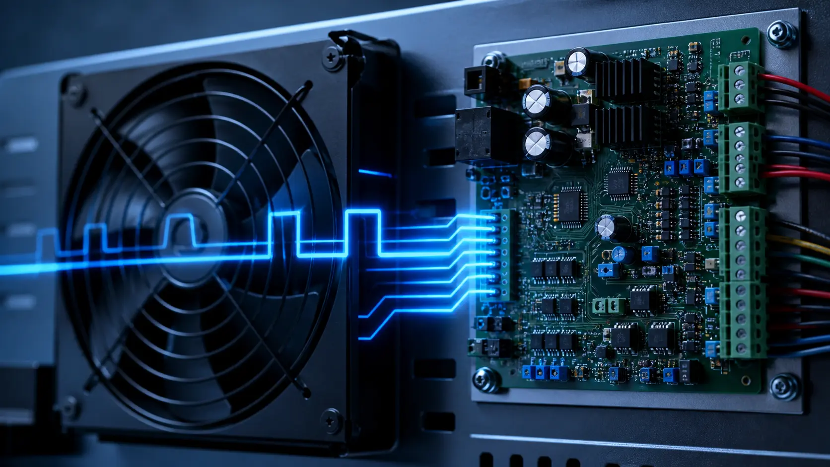
A pulse-width-modulated signal is a square wave at a fixed frequency whose duty cycle — the fraction of each period spent HIGH — carries the command. 50% duty means the transistor is on half of every cycle; the fan's internal driver integrates this into an effective average drive. Nothing about the supply voltage changes; only the on-time fraction does.
For 4-wire fans, the switching happens inside the fan, on its own motor driver. The host supplies only a small logic-level signal on the PWM pin — the fan does the heavy switching. This is the whole point of the 4-wire standard: the electrical noise of chopping motor current stays inside the fan, out of the host board, instead of modulating a shared power rail the way 3-wire (voltage-controlled) designs do.
For the Intel desktop 4-wire interface, 25 kHz is the nominal PWM frequency, with an approximately 21–28 kHz operating range in Intel reference requirements. That range keeps the control signal above the audible band for the intended interface, but a custom fan or controller can specify a different range. Confirm frequency, polarity, logic limits and drive topology against the selected fan's datasheet.
One caution about the specification: it defines an interface, not a universal response. Duty cycle is a command, and the RPM, minimum speed, start behavior and acoustic response for a given command are defined by each manufacturer's fan design.

- PWM = fixed-frequency square wave; the duty cycle carries the command
- 4-wire fans switch internally — the host provides only a logic-level signal
- 25 kHz nominal in the Intel reference interface; verify the allowed range for the selected fan
- The spec defines the interface, not the duty-to-RPM response — read the vendor curve
The 4-Wire Interface, Pin by Pin
Four pins, four jobs. Two are trivial, one is often ignored, and one destroys GPIOs when wired carelessly.
The common 4-wire arrangement carries: pin 1, ground; pin 2, fan supply; pin 3, TACH (also called FG, frequency generator); pin 4, PWM input. Pin 2 powers the fan from the supply rail directly — it is not a logic pin and must never be fed from a controller output. Pin 4 is the speed command, but frequency, polarity, voltage limits and whether the host should use an open-collector/open-drain driver must be confirmed from the fan specification.
Pin 3 is where many integration mistakes happen. TACH is commonly an open-collector or open-drain output: the fan pulls the line low and the host provides the pull-up. That pull-up must go to a compatible host logic voltage, not automatically to the fan supply. Confirm the fan's output rating, pull-up range and controller input protection before connecting the GPIO.
TACH pulse count is model-dependent. Two pulses per revolution is common, but the controller must use the specified pulses-per-revolution value: RPM = TACH frequency × 60 / PPR. For example, a fan specified at four pulses per revolution that produces a 200 Hz TACH signal is running at 3,000 RPM (200 × 60 ÷ 4). Record the specified PPR with the measurement; otherwise a perfectly clean waveform can still become a wrong RPM value.
When the controller reports zero RPM, verify the waveform at the controller pin before changing the fan. The fan may be below its stable speed, the pull-up may be missing, the input capture window may be too short, or the line may be open. A short oscilloscope or logic-analyser capture at minimum duty, nominal duty and startup makes those cases distinguishable and creates an evidence trail for a replacement-fan review.
A related but distinct variant is the RD (rotating detect) output, common on some industrial fans. RD holds one state while the fan spins and changes state when it stops — a locked-rotor alarm, not a speed signal. It answers 'is it turning?', not 'how fast?'. Substitute it where tachometer feedback is expected and the control loop has nothing to integrate against.

- Pin 1 GND · Pin 2 +12 V supply · Pin 3 TACH/FG · Pin 4 PWM in
- TACH is commonly open-collector/open-drain — pull up to a compatible HOST logic voltage
- RPM = TACH Hz × 60 / PPR; use the pulses-per-revolution value in the fan specification
- RD is a rotate-detect alarm (stopped/spinning), not a speed signal — do not confuse the two
Control Interface Acceptance Matrix
Treat the PWM connection as an electrical interface contract, not as four wires that are interchangeable across vendors.
Before connecting a replacement fan, record the host output type, PWM frequency, logic-high and logic-low levels, polarity, pull-up or open-drain arrangement, fan supply range, TACH pulses per revolution and the meaning of an absent or invalid signal. The exact fan datasheet and controller specification must agree on each item.
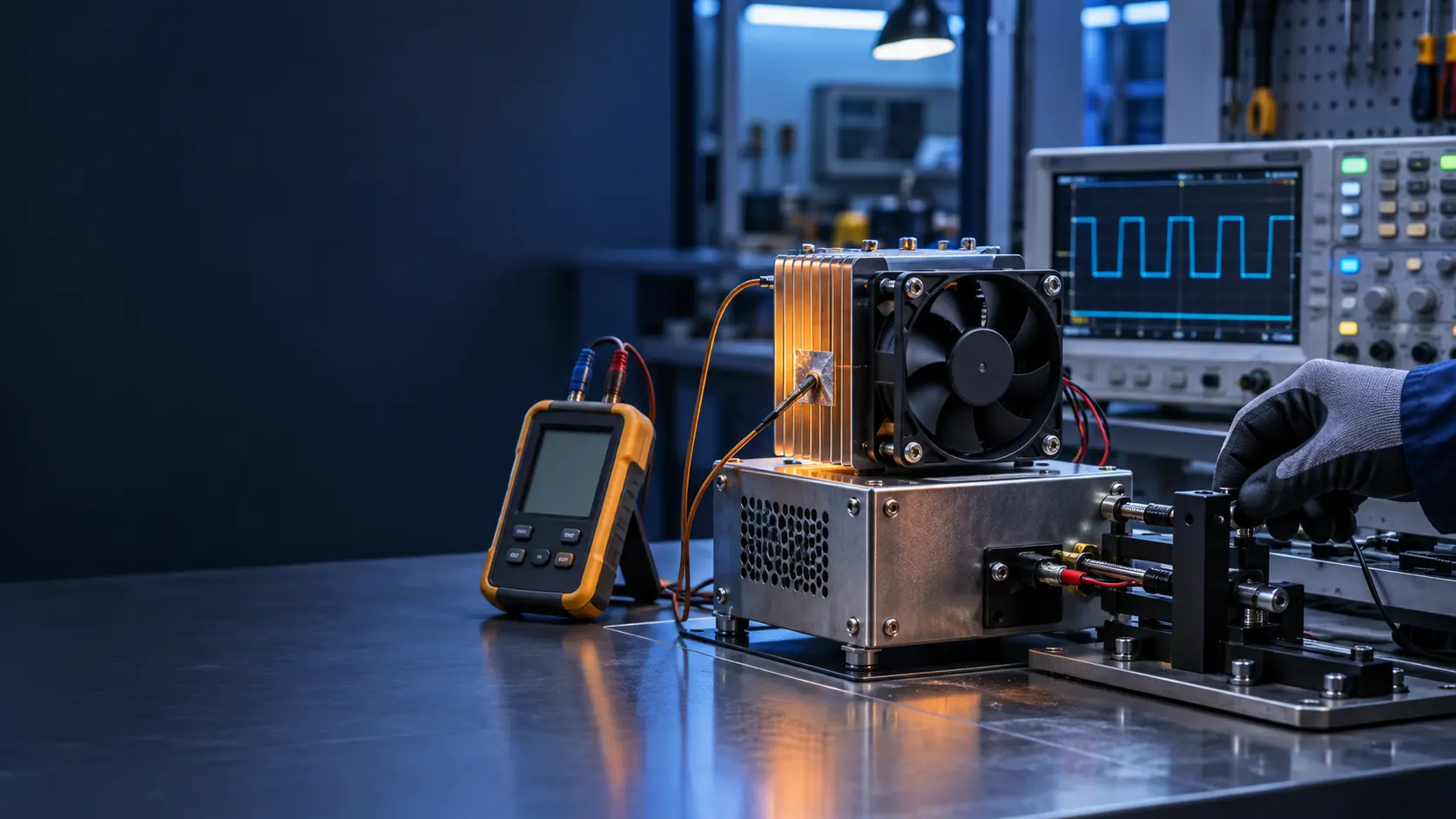
A practical bench check uses an oscilloscope or logic analyser for PWM and TACH, a current probe or shunt for startup current, and a tachometer or frequency measurement for RPM. Test power-on, controller reset, PWM disconnected, TACH disconnected, fan stalled and fan reconnected while recording the product's fault response.
The interface is not complete until the controller knows what to do when the fan is deliberately stopped, when the fan has not yet started, and when a tachometer line is open. A zero-RPM reading can mean stopped by command, failed fan, missing pull-up, wiring fault or a tach signal below the measurement window.
- PWM frequency, polarity, logic levels and driver topology.
- Fan supply range, startup current and startup duration.
- TACH/FG output type, pull-up voltage and pulses per revolution.
- RD/alarm state and the controller's response to missing feedback.
- Power-on, reset, disconnect, stall and recovery behaviour.
The Duty Cycle Dead Zone
The most valuable line in a PWM fan's datasheet is not the top speed. It is the duty below which the response stops being predictable.
There is no universal PWM duty-cycle floor. Some fans hold a minimum speed, some stop below a defined command, and some require a restart sequence after stopping. Others may run over a wide range but with a nonlinear duty-to-RPM response. The usable range is a property of the specific fan, controller interface and supply condition.
The specification usually tells you which behavior to expect — but only if you read the PWM section of the datasheet rather than the headline table. Two fans with identical top-end curves can have completely different response shapes near minimum duty, and products that assume a universal floor can ship erratic thermal behavior. A lookup table can also chatter if its thresholds and hold times are poorly chosen, so verify the complete control sequence rather than assuming it is automatically stable.
Starting is a separate event from running. Breakaway torque at standstill is higher than running torque, so the duty that sustains rotation is often well below the duty that initiates it. A fan that cruises happily at 40% may need 60% or more to start from rest. Robust implementations either command a start-up burst, use the TACH signal to confirm spin-up before throttling back, or simply floor the control floor high enough that the issue never arises.
A third symptom deserves its own mention: RPM hunting. If a closed-loop controller corrects aggressively, the fan speed oscillates around the setpoint — audible as a slow, periodic rise and fall. The fixes are control-side (see the next section), but the root cause is the same aggressive tuning meeting a plant with lag.

- Usable control band: determine it from the selected fan's duty-to-RPM data
- Below the validated band: minimum speed, full stop, or unstable running — varies by model
- Start-up duty typically exceeds running duty — verify breakaway on the real fan
- RPM hunting: speed oscillating around setpoint — a controller tuning problem, not a fan defect
Choose the Control Variable Deliberately
A PWM duty command, a target RPM and a temperature setpoint are three different control decisions.
In open-loop control, the controller maps temperature or load to a PWM duty and accepts that the resulting RPM will vary with supply voltage, fan tolerance, air-path resistance and temperature. This can be simple and stable, but the product must be validated across those conditions. A duty value is not a guaranteed airflow or RPM value.
In an RPM loop, the controller reads TACH and adjusts duty to hold a target speed. That can compensate for some fan-to-fan and restriction changes, but it does not guarantee a thermal result: the same RPM can produce different airflow when a filter loads or the inlet geometry changes. In a temperature loop, the controller protects the measured component or air temperature, but sensor location, thermal lag and control tuning become part of the result.
NVIDIA's fan-control documentation illustrates this distinction by separating open-loop PWM profiles from closed-loop RPM control, while Microchip's PID reference uses tachometer feedback to regulate a 4-wire fan. For a product design, choose the variable that matches the requirement, then define limits for the other variables: maximum temperature, minimum airflow, maximum noise, speed range and safe response to missing feedback.
- Open-loop PWM: simple command, but RPM and airflow must be mapped across conditions.
- Closed-loop RPM: stabilizes speed, but does not remove system-curve or thermal validation.
- Temperature loop: protects the measured location, but depends on sensor placement and thermal lag.
- Define maximum temperature, minimum airflow, speed, noise and fault limits together.
- Test supply variation, filter loading, fan tolerance and sensor faults before release.
Closed-Loop Control: From Command to Consequence
An open-loop PWM command hopes. A closed-loop controller, reading TACH and a temperature sensor, knows — and knowing is what separates a thermal design from a thermal guess.
The minimal control loop is: read the temperature (or the TACH), compare against target, adjust duty. Most implementations land on a PID structure, and most PID-in-cooling problems come from tuning it like a motor controller rather than a thermal system. Thermal plants are slow and lagged; aggressive gains produce overshoot and the RPM hunting described above. The proportional term nudges, the integral term removes steady-state error — and that integral term, fighting sensor noise or a lagging plant, is the usual source of oscillation.
Two structural alternatives avoid the trap. The first is a stepwise (linear or multi-point) control curve: a fixed lookup table from temperature to duty, verified on the bench, with no integrator to wind up. It cannot oscillate; it can only be slightly wrong — and it is what many mature products ship. The second is hysteresis: widen the deadband around the setpoint so the controller does not chase every tenth of a degree, and quantise speed changes to a few percent with a minimum hold time between adjustments.
More advanced loops add feed-forward: use known load indicators — power draw, clock activity, measured heat input — to pre-position the duty estimate, letting feedback trim rather than drive. This is the standard structure in server fan control, where a slow integral-only loop paired with a fast power-based feed-forward keeps hundreds of fans quiet and stable.
Whatever the loop, failsafe behavior is not optional. If the TACH signal disappears, the temperature sensor reads implausible, or the controller itself hangs, the product should enter its defined safe cooling state — commonly a high or full-speed command, subject to the fan and system limits. Cooling is the one subsystem where failure must fail cold, not silent and hot. Watchdog-driven failsafe logic belongs in the first design pass, not the last.
- PID works, but thermal plants lag — gentle gains beat sharp ones
- Stepwise temperature-to-duty tables: cannot oscillate, easy to bench-verify
- Hysteresis and minimum hold times stop the controller chasing sensor noise
- Feed-forward from power telemetry pre-positions duty; feedback trims
- Defined safe cooling state on missing TACH, bad sensor, or controller hang
What PWM Buys You: The Fan Laws in Action
The payoff of everything above is quantified by three scaling laws. The interactive model below applies them to a schematic fan so the numbers can be felt, not just quoted.
Drag the duty slider and watch the schematic fan respond. In the linear band, speed follows duty; airflow follows speed; pressure capability follows the square; and power follows the cube for corresponding points on the same fan family. The familiar half-speed, roughly one-eighth-power example is an affinity-law estimate, not a promise for an installed fan: the system curve, motor electronics, controller losses and operating point still determine the actual input power. The acoustic result must also be measured rather than inferred from speed alone.
Compare a 4-wire PWM interface with voltage control on a 3-wire fan. Voltage control changes the fan's supply and its usable range depends on the motor electronics, minimum operating voltage and load. A 4-wire interface keeps the fan supply present while a separate control input commands speed, but the achievable minimum speed and regulation still depend on the selected fan. Validate both interfaces against the actual voltage range and duty-to-RPM curve.
The model makes one more point visible: below the control floor, reducing duty buys nothing. A command of 10% costs the same min-speed operation as 20% on a Type-A fan — or a stopped fan on a Type-B. The control range you verify on the bench is the range you can actually use in the product.
One honest caveat, as always in this series: the model applies the affinity laws to an illustrative 10,000 RPM fan with a schematic dead zone. It demonstrates the mechanics of duty-cycle response; it is not representative of any specific product's measured data, and real control curves always come from the manufacturer.
Customize the control interface and validate the fan in the product
PWM is only useful when the fan's response, feedback and failsafe behavior match the customer's controller and thermal path.
MEGA Tech can help product teams define the control requirement together with the fan requirement. We review voltage, speed range, heat load, airflow and pressure, noise target, PWM frequency and duty range, FG or RD feedback, connector, cable length, startup behavior, minimum speed and fault response. This gives the controller a known fan behavior instead of assuming every 4-wire fan responds the same way.
The fan configuration can be customized around frame size and thickness, airflow and static pressure, motor speed, PWM response, FG or RD signal, connector and wiring, bearing choice, rotation direction, mounting and environmental protection. For a new product or a small first build, we can develop a sample and map duty-to-RPM, startup threshold, pressure performance and feedback behavior on the representative enclosure.
Validation should cover cold start, minimum duty, normal and peak thermal load, missing feedback, controller reset, loaded filters, noise and continuous operation. We refine the control and fan configuration with the customer, document the verified operating window and then transfer the approved combination into stable volume production.
- Define PWM, feedback, startup, minimum-speed and failsafe behavior early.
- Customize the fan's electrical, mechanical, control and wiring details.
- Map control response and validate faults in the representative product.
- Carry the verified fan-control combination into repeatable production.
Engineer FAQ: PWM, TACH and Fan Faults
These questions address the control failures that are often discovered only after a replacement fan is installed.
Q: Is 25 kHz required for every 4-wire fan? A: No. It is common in the Intel reference interface, but the selected fan and controller must agree on frequency, polarity and logic levels.
Q: Why does the fan run at full speed when PWM is disconnected? A: That may be the fan's defined fail-safe state, but it is model-dependent. Confirm the input bias and loss-of-signal behaviour instead of assuming it.
Q: Why does TACH show zero RPM at low duty? A: The fan may be below its stable operating range, the pulse frequency may be below the controller window, or the pull-up/wiring may be wrong. Confirm the waveform at the host pin.
Q: Can RD replace TACH? A: No. RD generally reports rotating or stopped status; TACH/FG provides a pulse frequency that can be converted to RPM.
Q: Should the controller reduce duty immediately after startup? A: Only after the fan has reached a verified speed. Use a startup burst or a TACH-confirmed transition when the selected fan requires it.
Q: Is closed-loop RPM control enough to protect the product? A: No. RPM feedback can confirm rotation, but airflow still depends on the installed pressure path. Combine RPM monitoring with temperature or airflow evidence when the thermal margin is tight.
Q: What should happen if the controller or temperature sensor fails? A: Define a safe cooling state, commonly a high-speed command within the fan and system limits, and verify it with an injected fault.
- Interface compatibility must be tested, not inferred from connector count.
- Startup and running duty are different parameters.
- TACH is speed feedback; RD is a rotation alarm.
- Missing feedback and sensor faults need an explicit safe response.
A Practical Control Checklist
PWM speed control fails in known, repeatable ways. This checklist covers the ones that actually bite.
Electrical first. Confirm the PWM pin accepts your logic level, use the vendor's documented frequency range (25 kHz is common in the Intel reference interface), and pull TACH up to the host's logic rail — with a resistor value from the vendor's recommendation, typically a few kilohms. Route the PWM line away from motor current paths; most 'mysterious TACH glitches' are coupling, not logic.
Then behaviour. Verify start from rest at your minimum commanded duty, on a cold fan, at your lowest expected ambient. Map the real duty-to-RPM response on a sample of fans, not one — the dead-zone edge varies unit to unit. Set the control floor above the worst measured unreliable point, and decide explicitly what 0% means for your product: stopped fan with a restart strategy, or minimum-speed hold.
Then control. Choose the loop structure that matches your software maturity: a verified stepwise table if you need guaranteed stability, PID with hysteresis and slew limiting if you need tracking. Add feed-forward if you have a load signal. And design the failsafe before the features: missing TACH, implausible temperature, controller hang — all must end at full speed.
Finally, listen. Acoustics close the loop that thermodynamics opens: a system that is quiet at idle, inaudible during typical load, and only spins up briefly under genuine stress is the audible signature of a control loop tuned well.
- PWM at 25 kHz, logic-level on pin 4; TACH pull-up to host 3.3 V rail
- Verify cold start at minimum duty; map the response on multiple units
- Set the control floor above the dead zone; define what 0% means in your product
- Stepwise table for guaranteed stability; PID with hysteresis for tracking
- Defined safe cooling state on missing TACH, bad sensor, or watchdog expiry