A noisy fan curve is often a thermal-control problem
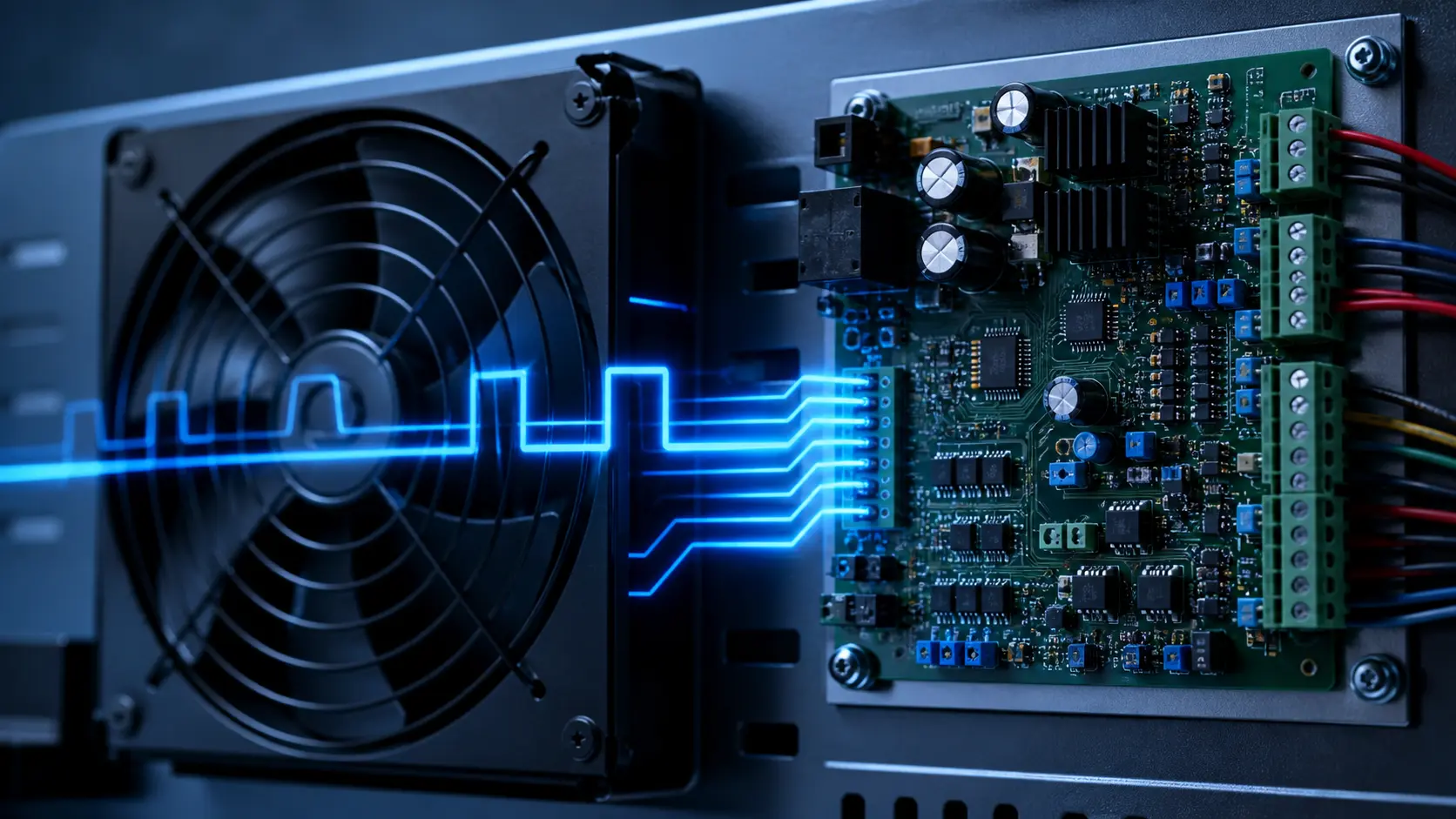
If fan RPM rises, temperature drops, RPM falls and the cycle repeats, the fan may be responding exactly as commanded to a control loop that has no stable deadband.
Engineers commonly see this near a temperature threshold: the sensor moves by a small amount, the controller changes duty, airflow changes, and the sensor immediately crosses back. The audible result is an irritating ramp. The thermal result can be worse: repeated starts, speed changes and incomplete cooldown make it difficult to judge the true thermal margin.
Analog Devices describes fan control around a minimum temperature, maximum temperature, speed slope and turn-off hysteresis. Its examples also use a momentary full-speed start before returning to the minimum speed. These are useful control elements, not universal values: the sensor, fan, enclosure and thermal time constant decide the settings.
Screen the control loop before changing the fan
Use the interaction as a discussion aid: it shows why a narrow deadband can react to signal noise, while a low PWM command still has to be proven stable on the real fan.
The display is deliberately not a temperature predictor. It cannot know a device heat capacity, heat-sink resistance, fan curve or firmware sampling scheme. Its purpose is to make the checks visible before a team treats an oscillating RPM trace as a fan defect.
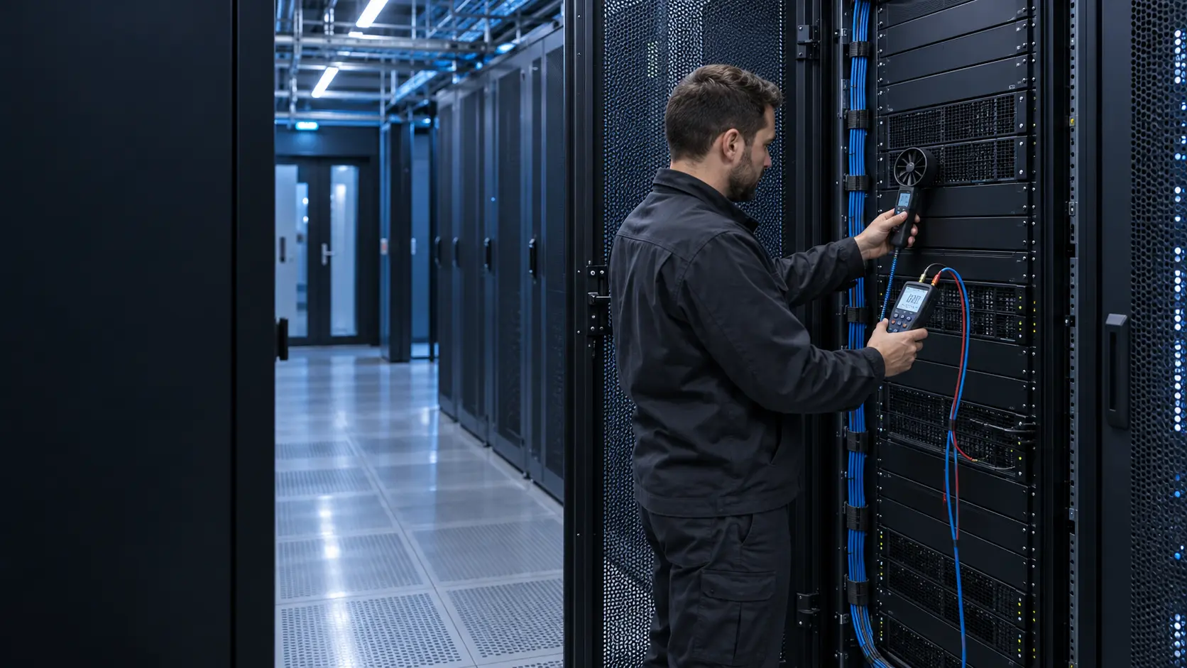
- Record raw and filtered sensor temperature, PWM command, tach RPM, supply voltage and component temperature on one time axis.
- Test the actual startup, restart and lowest commanded speed at the product voltage and installation restriction.
- Change one control variable at a time and preserve the physical test configuration.
Put the sensor where the thermal decision is made
A sensor on an exhaust stream can react rapidly to fan speed, which may amplify the controller's own action. A sensor far from the heat source can react too slowly and hide a local component excursion. A junction or close-to-hotspot measurement can be more representative, but it may need filtering and a defined fallback if the sensor fails.
This is why sensor placement is an engineering decision rather than a firmware default. The review should identify the protected component, the expected heat path, the sensor mounting method, sensor-to-hotspot lag, electrical noise exposure and the maximum permitted temperature under a sensor or fan fault.
Use hysteresis, filtering and ramp rate for different jobs
Hysteresis creates separate rising and falling thresholds, preventing a state change every time the measured temperature crosses one point. Filtering reduces short-duration sensor noise. Ramp rate limits how quickly a PWM command changes. They are complementary: a filter cannot replace a deadband, and a large deadband cannot repair a sensor that is measuring the wrong thermal mass.
A control review should also define minimum on-time, minimum off-time and fault behaviour where the product permits them. The target is not the smoothest graph at any cost; it is stable cooling while keeping the protected component inside its documented limit during realistic workload transitions.
| Item | What to record | Why it matters |
|---|---|---|
| Temperature input | Raw value, filtered value, location and sample interval | Separates sensor noise or delay from actual heat change. |
| Fan command and feedback | PWM/voltage command, tach RPM, supply voltage and current | Shows whether the fan follows the command and remains stable at low duty. |
| Thermal response | Protected-component temperature during step load and cooldown | Shows whether the selected curve protects the real heat source. |
| Fault response | Open/short sensor, stalled fan or lost command behaviour | Defines the safe state instead of assuming normal feedback persists. |
Validate the minimum usable fan command
A fan can rotate at a duty that does not start it reliably after a stop, or it can report unstable RPM at a low command. The threshold is model-, voltage-, temperature- and installation-dependent. Measure it rather than assuming that a percentage which works on one fan will transfer to another.
For a 4-wire fan, check the PWM input behaviour, tach pulse quality and any start-boost requirement against the manufacturer documentation. For two-wire or voltage-controlled fans, check the actual supply at the fan terminals under current, including cable drop and controller behaviour. A command signal is not evidence of delivered airflow.
Engineer FAQ: Fan Control Hunting
Q: Does fan hunting mean the fan is defective? A: Not necessarily. First compare temperature, command, RPM and voltage. A repeatable command oscillation often starts in the sensor or control logic; unstable RPM at a fixed valid command can point to a fan, supply or interface issue.
Q: What hysteresis should I use? A: There is no transferable universal value. Select it from allowable component temperature range, sensor noise, thermal lag, heat-load step and acoustic expectation, then test rising and falling transitions.
Q: Can I cure hunting only by averaging the temperature? A: Averaging may reduce noise but also adds delay. Pair it with an appropriate deadband, ramp strategy and a sensor placed for the component being protected.
Q: Should the fan turn fully off at low temperature? A: Only if restart reliability, condensation, acoustic needs, standby heat and fault response are validated. A defined low-speed state can be safer than repeated on/off switching in some products.
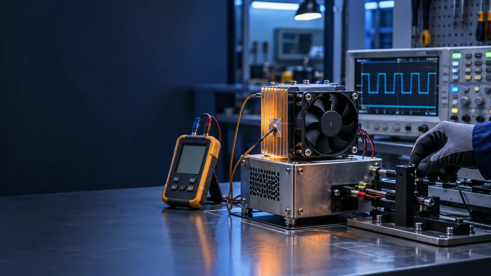
Q: What must a custom fan sample prove? A: Start and restart, stable low-speed operation, tach or alarm behaviour, airflow and noise at installed pressure, and thermal response under representative worst-case load.
Develop a stable cooling response around the real product
MEGA Tech can help define a practical cooling-fan sample around the required voltage, pressure, control signal, feedback, space, noise and environment. The control curve belongs in that sample plan: the approved configuration should be tested with the representative heat source, sensor position, firmware limits, wiring and airflow path.
The release record should preserve the fan configuration, control interface, start condition, minimum stable speed, alarm behaviour, measurement points and acceptance limits. That lets a prototype decision become a repeatable production baseline rather than a bench-only fan curve.
- Start with the protected component and its allowable temperature, not a generic fan percentage.
- Test sensor placement, heat steps, speed ramp and low-duty stability in the assembled enclosure.
- Log command, RPM, temperature, voltage and airflow-path configuration together.
- Freeze the accepted fan and control behaviour before volume production.
Measure the loop before changing the controller
Speed hunting is a closed-loop symptom, not a diagnosis. Before changing gains, log the command, measured RPM, FG period, temperature, pressure or airflow, supply voltage and the time between command changes. Include the sensor location and the physical distance from the heat source. A controller can hunt because the sensor is noisy, because the fan has a slow response, because the air path has recirculation, or because the control target is inside a region where small duty changes create large temperature changes.
Run the system with a fixed command first. If temperature and airflow are stable at fixed duty, the mechanical path may be acceptable and the problem may be loop tuning or sensor placement. If the system is unstable with fixed duty, inspect mounting, obstruction, filter movement and thermal coupling before tuning. This simple split prevents a software change from hiding a physical fault.
Record at a sample interval that can see the oscillation. A one-minute log can hide a two-second cycle; a very fast log can obscure the slower thermal trend unless both are recorded. Keep the raw data and annotate command changes, service actions and environmental changes.
| Observation | Likely branch | Next check |
|---|---|---|
| RPM and command oscillate together | Control loop or sensor delay | Command-to-RPM and sensor timing |
| RPM stable, temperature oscillates | Thermal coupling or airflow path | Probe location and pressure |
| Command stable, RPM unstable | Supply, harness or fan-side issue | Connector waveform and current |
| Only one installation hunts | Mounting or system effect | Compare geometry and restriction |
Use hysteresis and placement as engineering parameters
Hysteresis prevents a controller from changing state every time a noisy measurement crosses one threshold. Define the rising and falling thresholds, minimum dwell time and the maximum allowed response delay. These values should be tested against the thermal storage of the equipment: too little hysteresis can create audible speed changes; too much can allow an avoidable temperature excursion.
Sensor placement often matters more than a new gain value. A probe in a supply jet may read cool air while the heat source is hot; a probe too close to an outlet may see recirculated air; a probe mounted on a vibrating bracket may add electrical noise. Map several locations at low, normal and peak load, then choose the point that tracks the protected condition with the least delay and least local disturbance.
For BESS or cabinet systems, also compare the sensor reading with differential pressure and fan feedback. If the fan command rises while pressure increases and airflow falls, the loop may be reacting to a restriction rather than a capacity shortage. That case needs an air-path service action, not an unlimited speed increase.
- Define separate rising and falling thresholds.
- Set a minimum dwell time and test it against thermal lag.
- Correlate sensor position with the protected component.
- Check pressure and airflow before increasing maximum duty.
Verify the tuned loop at boundaries and after service
A stable middle-of-range run does not prove a robust controller. Test the lowest and highest normal loads, minimum and maximum allowed supply voltage, cold and warm start, clean and loaded filter, and the expected ambient range. Observe whether the fan reaches the required operating point without repeated reversals or audible cycling. If a service action changes the filter or cable route, repeat the critical points because the system curve may have changed.
Use acceptance criteria that a technician can reproduce: maximum command changes per minute, maximum temperature deviation, minimum airflow or pressure, maximum noise change and alarm behavior. Avoid a criterion that depends on a particular controller log format only. The installed fan, path and sensor should remain within the same evidence boundary after production changes.
The supplier discussion should include the pressure and airflow at the target command, the control interface, the expected temperature basis and the sample mounting. MEGA Tech can help review and customize a fan sample; the equipment owner remains responsible for the loop, sensor and protection strategy.
Engineer FAQ: fan-control hunting
Q: What is the first test? A: Hold the fan at fixed duty and record temperature, pressure, airflow and RPM. This separates a physical instability from a control-loop instability.
Q: Is more hysteresis always better? A: No. It reduces switching but can delay thermal response. Choose rising, falling and dwell values against the measured thermal lag.
Q: Why can moving a sensor fix the problem? A: A better location can reduce delay, jet bias, recirculation bias and noise, so the controller sees the protected condition more faithfully.
Q: Can higher maximum RPM solve hunting? A: Not if the path is blocked or the sensor is wrong. It can add noise and power while leaving delivered airflow unchanged.
Q: What should be repeated after a filter change? A: The operating point, thresholds, airflow/pressure, temperature response and alarm behavior at the service condition.