A spinning fan is not proof of cooling
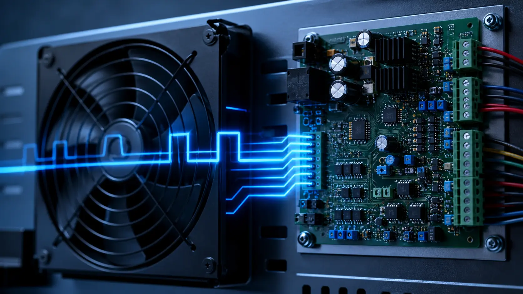
TACH/FG reports rotation; it does not measure useful airflow through the protected heat source.
A blocked grille, loaded filter, bypass path or recirculation route can leave RPM close to expectation while component temperature rises. Treat RPM as one diagnostic layer, not the thermal acceptance result.
The validation record must align fan command, actual RPM, supply voltage, differential pressure or delivered flow, and protected-component temperature on one time axis.
TACH, RD and temperature answer different questions
TACH/FG supplies pulses used to calculate speed. RD or locked-rotor output is a discrete fault indication whose polarity and behavior must come from the exact fan datasheet. Neither proves the installed air path is open.
Use the thermal sensor to protect the component, and use pressure or airflow evidence where a blocked path is a credible failure mode.
| Signal | What it can show | What it cannot prove |
|---|---|---|
| TACH / FG | Rotation or underspeed | Delivered airflow through the enclosure |
| RD / locked rotor | Defined fan fault state | Pressure margin or heat-source cooling |
| Pressure / temperature | Path restriction or thermal consequence | Root cause without the other signals |
Screen a fault response before production
Use the interactive control display to discuss sensor noise and minimum stable speed, then validate the actual fault response on the assembled unit.
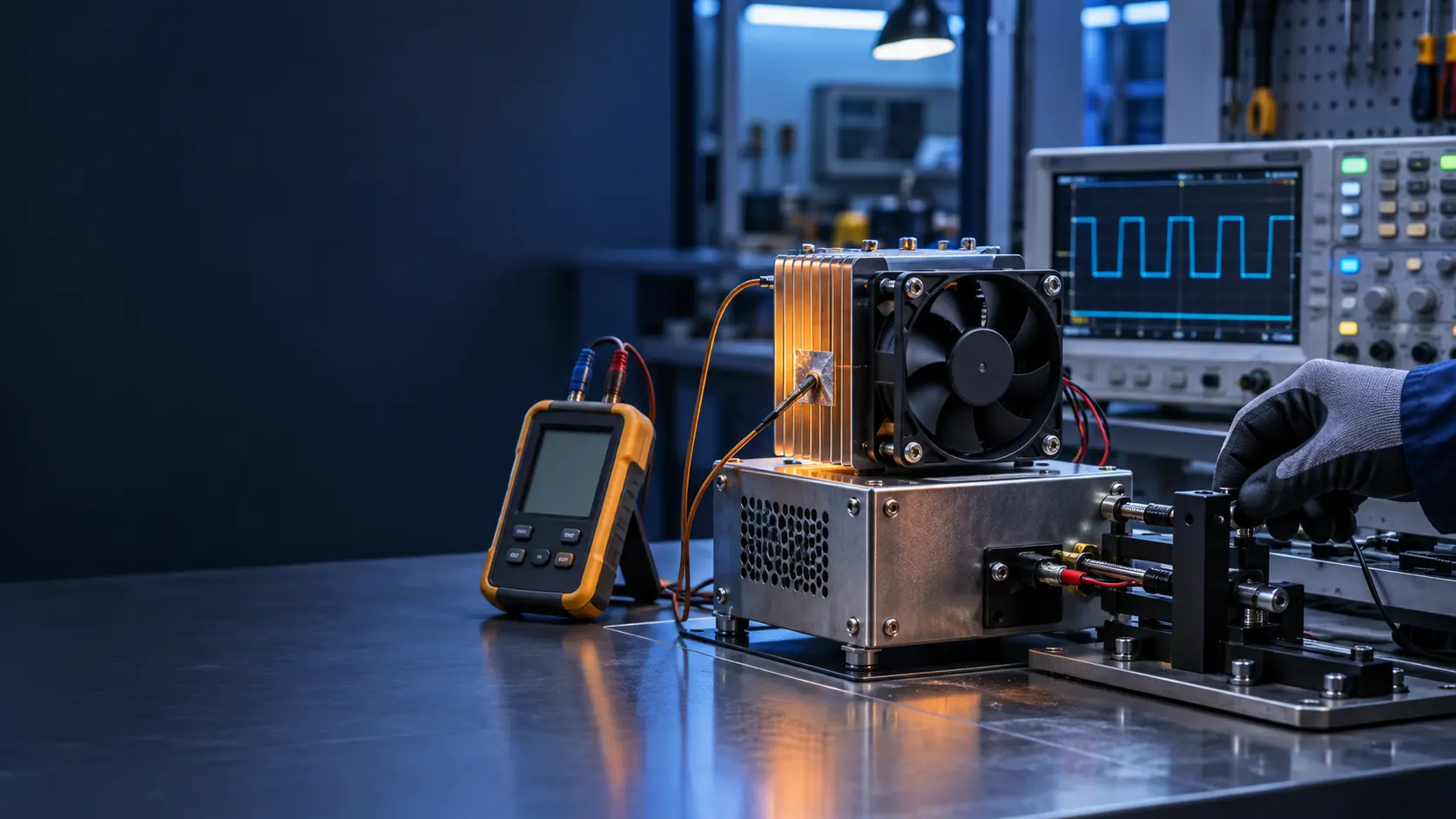
Stop a fan or simulate its declared alarm state at representative load. Record detection delay, fallback command, remaining airflow, pressure and protected-component temperature. Repeat with the representative filter, grille and cable routing installed.
- Define normal, warning, alarm and safe-state actions.
- Verify open/short sensor and lost-command behavior.
- Do not clear an alarm solely because RPM returns; confirm temperature and airflow-path recovery.
Engineer FAQ: TACH and RD
Q: Can normal TACH prove the fan is cooling? A: No. It proves rotation at a reported speed, not installed airflow or component temperature.
Q: Should RD replace TACH? A: No. RD can simplify a defined fault indication; TACH provides speed evidence. Choose from the safety and diagnostic requirement.
Q: What should a custom sample prove? A: Start, restart, low-speed stability, signal behavior, installed airflow or pressure, temperature and fault response.
Build the fan and fault logic around the real enclosure
MEGA Tech can help define fan voltage, PWM, FG/RD behavior, connector, pressure duty and validation method around the customer enclosure. Approve the sample only after the required thermal and fault states are demonstrated.
- Specify signals from the exact electrical interface.
- Measure pressure or flow and temperature with RPM.
- Freeze the accepted fault behavior in the production release record.
Build a time-aligned fault record
A fault decision is only as good as the evidence captured at the same moment. Log the commanded PWM duty, supply voltage at the connector, measured RPM, FG pulse frequency, RD state, differential pressure across the path, airflow where it can be measured, and the protected temperature. A controller log that contains only RPM can miss a fan running against a blocked filter or a fan spinning in a bypass path.
Use a common timestamp and identify the measurement location. State whether pressure is static or differential, whether airflow is free-air or installed, and whether the temperature probe is on the component, inlet air or exhaust air. Repeat the record at start-up, steady load, commanded low speed, commanded high speed and the fault state. This turns a “fan fault” into a traceable chain from command to physical consequence.
For a sample review, keep the same record format for every candidate. The point is not to create a perfect laboratory model; it is to make two fan samples comparable under the same restriction, voltage tolerance and thermal load. If an alarm threshold changes, preserve the old trace so the effect of the change can be reviewed rather than guessed.
| Record field | Why it matters | Acceptance question |
|---|---|---|
| Command and voltage | Shows what the controller requested and what reached the fan | Did the fan receive the intended electrical condition? |
| RPM and FG | Shows rotation and signal continuity | Is the pulse train plausible for the commanded speed? |
| RD state | Shows the declared discrete fan fault | Does polarity and delay match the exact interface? |
| Pressure, flow and temperature | Shows installed cooling consequence | Did the protected load remain inside its limit? |
Separate electrical, mechanical and air-path faults
Start with the least invasive checks. Measure voltage at the fan connector during start-up and at the moment of an alarm; a long harness, undersized connector or shared supply transient can create a fan symptom without a failed motor. Then verify the command reference, PWM frequency or control polarity against the selected fan interface. A stable command with no rotation points to a different branch than a missing command or a collapsing rail.
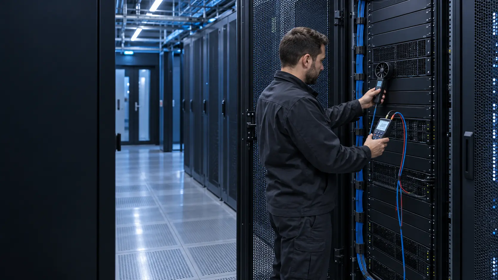
Next inspect mechanical conditions: mounting torque, gasket compression, cable contact, foreign material and bearing noise. A fan may show correct FG pulses while a bracket transmits vibration into the enclosure. Finally inspect the air path. A loaded filter, grille obstruction, reversed flow path or recirculation loop can preserve RPM and still reduce useful cooling. Use a pressure tap or a repeatable airflow measurement instead of judging the outlet jet by hand.
The fault tree should assign an action to each branch. Electrical loss may require a supply or harness action; a declared RD fault may require a controlled restart; abnormal pressure with normal RPM may require service of the filter or duct; an elevated component temperature with all fan signals normal may require an air-path or heat-source review. This prevents replacing a good fan to cure a system problem.
- Measure at the fan connector, not only at the power supply.
- Use the same mounting and restriction for every sample comparison.
- Treat normal RPM with high temperature as an unresolved air-path fault.
- Record the service action and the post-action pressure and temperature trace.
Set thresholds from evidence, not a single nominal RPM
A nominal speed is not a universal alarm threshold. Voltage tolerance, temperature, command duty, sensor resolution and the fan’s specified signal behavior all influence the observed value. Establish the normal band from repeated runs at the actual operating points, then add a warning band that allows the controller to distinguish a transient from a persistent deviation. The final threshold must also protect the application when the fan is still reporting a plausible speed.
Test low-speed startup separately from low-speed running. Some fans can run steadily at a duty that they cannot start against the installed pressure. Test a warm restart, a cold start, a supply dip and a restart after the RD state clears. If a fan is expected to restart automatically, define the retry interval and maximum attempts; if a technician must intervene, define the safe state and the information shown to the service team.
The production record should contain the exact fan revision, signal polarity, pulses per revolution if applicable, connector pinout, threshold, debounce time and the measured system consequence. That record is more useful than a generic statement such as “monitor RPM,” because it tells the next engineer what was actually validated.
Engineer FAQ: fan signal validation
Q: What if the FG frequency is stable but the heat sink is hot? A: Keep the fan signal as evidence of rotation, then inspect pressure, filter loading, recirculation and sensor placement. Do not close the fault until the protected temperature returns inside the approved limit.
Q: How long should an alarm be debounced? A: Use the application transient record and the exact fan signal behavior to choose it. A fixed value copied from another fan can hide a real start failure or create nuisance alarms.
Q: Should the alarm use RPM or temperature? A: Use both where practical. RPM can detect an early mechanical or electrical change; temperature protects the actual load. Pressure or airflow evidence is valuable when the air path can be blocked.
Q: What must be frozen before production? A: Pinout, signal polarity, pulse interpretation, thresholds, debounce, restart behavior, mounting and the installed pressure/temperature acceptance points.
Q: Can a custom fan supplier approve the whole fault strategy? A: The supplier can provide fan-side data and sample evidence; the equipment designer owns system-level protection, service logic and the final acceptance decision.
Close the evidence loop with an installed acceptance test
The final acceptance should be a short repeatable procedure, not a screenshot of one successful run. Install the approved fan in the real or representative enclosure, apply the defined command and load, and record the signal and thermal fields in the same order each time. Include a deliberate restriction or service condition only when it is part of the requirement, and label it clearly so a technician does not confuse a diagnostic challenge with normal operation.
After the run, compare the result with the approved limits and identify any assumptions that were not reproduced. If the measurement cannot be made directly, state the proxy and its uncertainty. A transparent limitation is safer than a false pass, especially when a normal RPM trace can coexist with low delivered airflow. Keep the sample revision and controller firmware in the record so a future change can be assessed against the same baseline.
Review service actions as part of validation
A diagnostic is incomplete if it says what the controller detects but not what the technician does next. Define whether the first action is to inspect the connector, clean the filter, check the mounting, replace the fan or reduce the protected load. After the action, repeat the relevant RPM, pressure and temperature checks. This keeps a good fan from being replaced for an air-path problem and gives the service team a measurable recovery condition.
The final record should also identify what information must be sent back to engineering: fan model and revision, voltage, command, RPM/FG, RD state, filter condition, pressure or airflow, temperature and the time sequence. That minimum packet makes a remote review useful and supports a controlled design change when a repeated field pattern appears.