IP rating is only one part of environmental protection
A fan IP code describes a defined ingress-protection test. It does not automatically qualify the complete enclosure, cable path or product duty.
Start by describing what the equipment actually sees: dust, water spray, oil mist, salt air, condensation, cleaning chemicals, vibration and temperature cycling. These stresses often arrive together, and the correct fan configuration may involve the frame, seal, connector, coating, filter and airflow path rather than IP code alone.
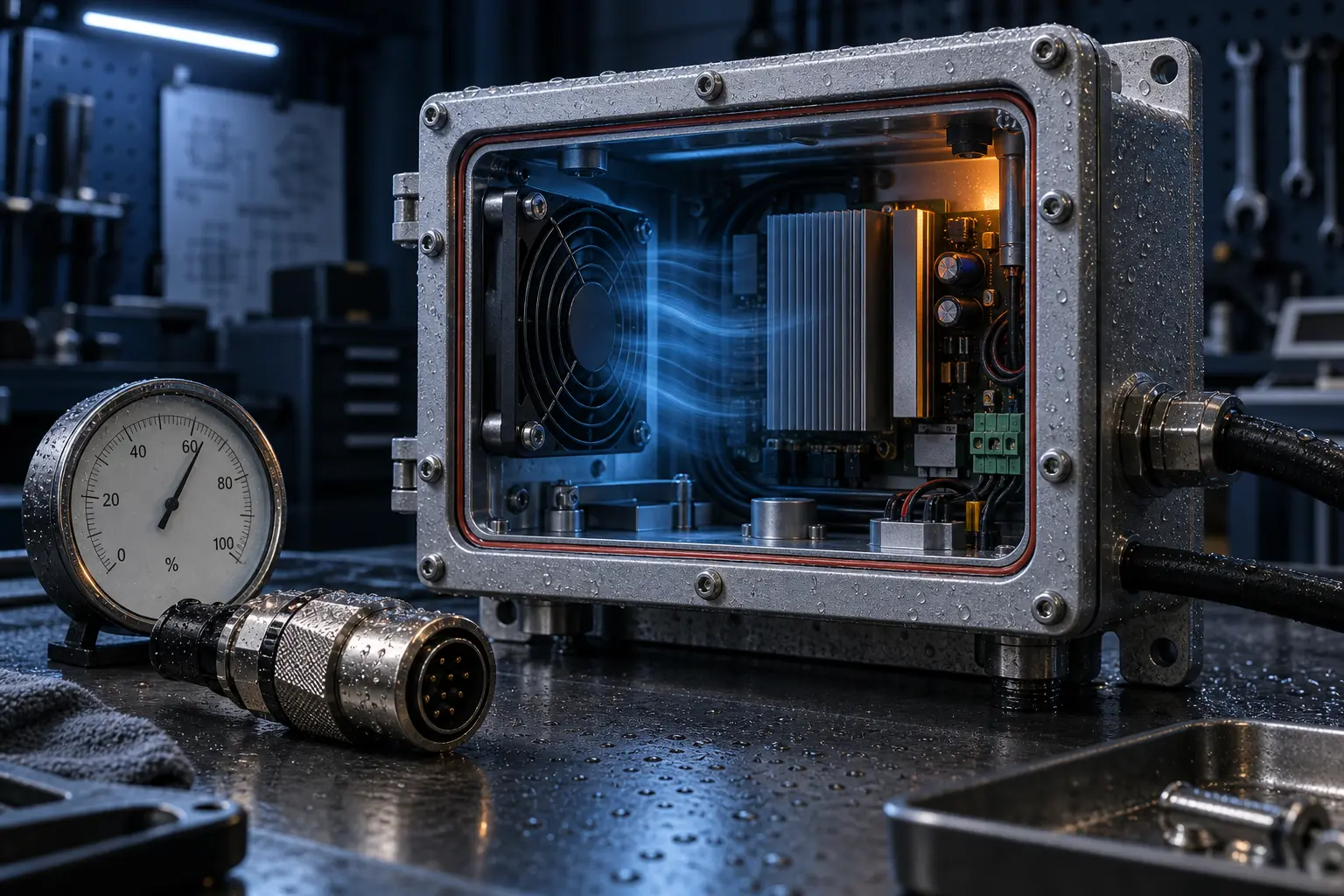
IEC 60529 defines the IP Code classification for protection provided by enclosures. Use it as a reference for the declared protection requirement, then verify the exact fan construction and the assembled product. A fan marked IP54 does not make an enclosure IP54 if the panel opening, cable gland or filter bypasses the protection path.
- Define the contaminant and exposure before choosing an IP number.
- Separate the fan rating from the enclosure and system rating.
- Check connector, cable exit, gasket and mounting interfaces.
- Validate protection after temperature cycling and vibration where relevant.
Translate the exposure into a test matrix
The same IP number can sit beside very different environmental risks. Write the exposure and pass criteria before selecting the fan construction.
Separate at least five questions: what solid contaminant is present, whether water is dripping or sprayed, whether oil or chemicals are present, whether the product crosses the dew point, and whether vibration or thermal cycling changes the seals. A dust test does not qualify salt mist; a water-ingress test does not prove corrosion resistance; and a steady humidity soak does not reproduce condensation during a cold restart.
Define the test boundary for the fan and for the assembled product. Record the exact fan model, protective parts, connector and cable route, mounting orientation, pressure drop, temperature and duration. For condensation, include cold soak, humidity, warm-up or power state, dwell and restart time. For dirty air, include filter loading, inspection points and the maintenance limit.
Manufacturer guidance also shows why scope matters: an IP claim may apply to specified live electrical parts rather than every mechanical or non-live component. Treat the fan's construction and the equipment enclosure as separate evidence packages, then verify the interface between them.

- Name the contaminant and exposure mechanism instead of using “outdoor” as a test condition.
- Separate dust, water, oil, salt, chemicals, humidity and condensation tests.
- Record mounting, connector, cable, gasket, filter and pressure-drop conditions.
- Define cold-start, thermal-cycle and maintenance acceptance criteria.
- Keep fan-level evidence separate from complete-equipment qualification.
Dust and filters change the operating point
A filter protects the fan and product, but its pressure drop is part of the fan selection and changes as the filter loads.
Measure or obtain the filter pressure-drop curve at the required airflow. Include the grille, heat sink, baffle, outlet and any narrow passage in the same pressure budget. A clean-filter result is only the beginning; define the replacement or maintenance condition that the product must tolerate.
As resistance rises, the operating point moves along the fan P-Q curve. Airflow can fall, component temperature can rise and the fan may run at a different speed or current. Do not promise a fixed percentage loss without the actual filter, dust loading and test conditions.
- Use the filter curve instead of a generic pressure allowance.
- Check clean, loaded and blocked-filter states.
- Monitor pressure, temperature or tachometer where maintenance matters.
- Keep enough service access to replace or clean the filter.
Humidity, condensation and corrosion need separate checks
High relative humidity is not the same as liquid water, and neither is the same as salt or chemical exposure.
Condensation occurs when a surface falls below the local dew point. A fan can operate within its stated temperature range and still face moisture on the PCB, connector or bearing if the product cycles between warm operation and a cold, humid environment. Define storage, transport, startup and operating conditions separately.
For coastal or industrial environments, ask about corrosion-resistant materials, PCB coating, connector sealing, fasteners and bearing protection. The fan's airflow may also draw contaminants deeper into the enclosure, so a higher IP number is not a substitute for a sensible inlet and service strategy.
- Calculate or measure dew-point risk during temperature cycling.
- Specify PCB, connector, cable and fastener protection separately.
- Consider salt mist, oil mist and chemical exposure as different tests.
- Validate startup after cold soak or condensation if the product requires it.
Worked Example: Condensation Is a Dew-Point Problem
Relative humidity alone is not enough to define condensation risk. Compare the dew point with the coldest surface in the fan and enclosure assembly.
As an illustrative condition, air at 30 °C and 70% RH has a dew point of approximately 24 °C. If a connector, PCB area, bearing region or enclosure wall falls below roughly 24 °C while that air is present, moisture can form. A fan remaining within its stated operating-temperature range does not by itself prevent this surface-level condensation.
The estimate depends on the measured temperature and humidity at the relevant location, not only the room sensor. During validation, log inlet air temperature, RH or dew point, the coldest accessible surface temperature, power state, warm-up time and restart behaviour. Repeat the check after cold soak, transport or a rapid ambient change when those events are credible in service.
This example is a dew-point estimate under stated conditions, not a universal environmental limit. Use the customer's climate profile, materials, insulation and product safety requirements to set the final acceptance threshold.
- Illustrative 30 °C / 70% RH condition: dew point is approximately 24 °C.
- Check the coldest surface, not the fan's average ambient temperature only.
- Validate cold soak, warm-up and restart when rapid changes are possible.
Specify the fan and enclosure as one airflow system
Protection features can add pressure drop, reduce free area or change noise. Environmental and thermal requirements must be reviewed together.
A sealed or filtered inlet can increase resistance. A rain hood, mesh, foam, membrane or labyrinth can create a different system curve from the open test setup. Use the actual protective parts in the thermal test and compare airflow, pressure, temperature, noise and power at the same operating point.
MEGA Tech can review the environment, available envelope, airflow path, pressure target, voltage, control interface and maintenance plan, then develop a sample around the required protection boundary. The approved configuration should record the exact fan, gasket, connector, filter and mounting details before production.
- Include protection parts in the pressure budget.
- Test thermal performance and environmental protection together.
- Document the approved fan, seal, connector and mounting configuration.
- Use a sample to confirm that added protection has not moved the design point.
Engineer FAQ: fan IP, dust and humidity
Answer these questions before approving an environmental fan configuration.
Q: Is IP54 always enough for industrial equipment? A: No. The required protection depends on the exposure, installation and product certification target.
Q: Does an IP-rated fan make the whole product IP-rated? A: No. The enclosure, openings, cable exits, filter and assembly must be qualified together.
Q: Can a fan operate in condensation? A: Only when the exact construction and product test support it. Check cold soak, dew point, startup and corrosion conditions.
Q: Does a filter improve or hurt cooling? A: It can protect the product while adding pressure drop. Select and validate it as part of the complete airflow path.
Q: If a filter pressure drop is lower than expected, is that always good? A: No. Check for air bypass around the filter frame, gasket or service door before accepting the result.
Q: What information should a custom fan supplier receive? A: Contaminant, humidity, temperature cycle, pressure target, airflow, voltage, noise, mounting, connector and required protection evidence.
- Fan IP and product IP are different claims.
- Condensation is a separate risk from humidity.
- Protection parts belong in the thermal operating-point test.
- Filter sealing affects both contamination control and fan operating point.
- Environmental claims require exact construction and test evidence.
Filter Integrity Is Different from Filter Resistance
A protected enclosure needs both the right filter pressure drop and a sealed filter frame. A low measured pressure drop can sometimes indicate bypass, not a healthy airflow path.
Filter media and the filter holder must be evaluated as one assembly. Gaps around the frame, a loose service door, a distorted gasket or an uneven clamp can let air avoid the media. The fan may then show an unexpectedly low pressure drop while dust and moisture continue to enter the enclosure through the untreated path.
At the design airflow, record clean-filter pressure drop, loaded-filter pressure drop and the expected service limit. Compare the result with the filter manufacturer's curve, inspect the frame for bypass and define how maintenance staff will know when the filter needs service. A differential-pressure switch, pressure transducer or documented replacement interval can be appropriate depending on the product and exposure.
The acceptance test should include the final fan, filter, gasket, access panel, cable route and enclosure pressure. Recheck it after vibration or thermal cycling if those conditions can change the seal. This connects environmental protection, fan operating point and maintenance instead of treating them as separate catalogue features.
- Measure pressure drop across the complete filter assembly, not only the media.
- Inspect and test frame, gasket, access panel and cable openings for bypass.
- Define clean, loaded and service-limit conditions.
- Add a pressure or maintenance indicator when filter loading can threaten cooling or protection.