A Clean-Bench Pass Is Not Thermal Margin
A fan that passes at room temperature with a clean path has cleared only one condition, not the application.
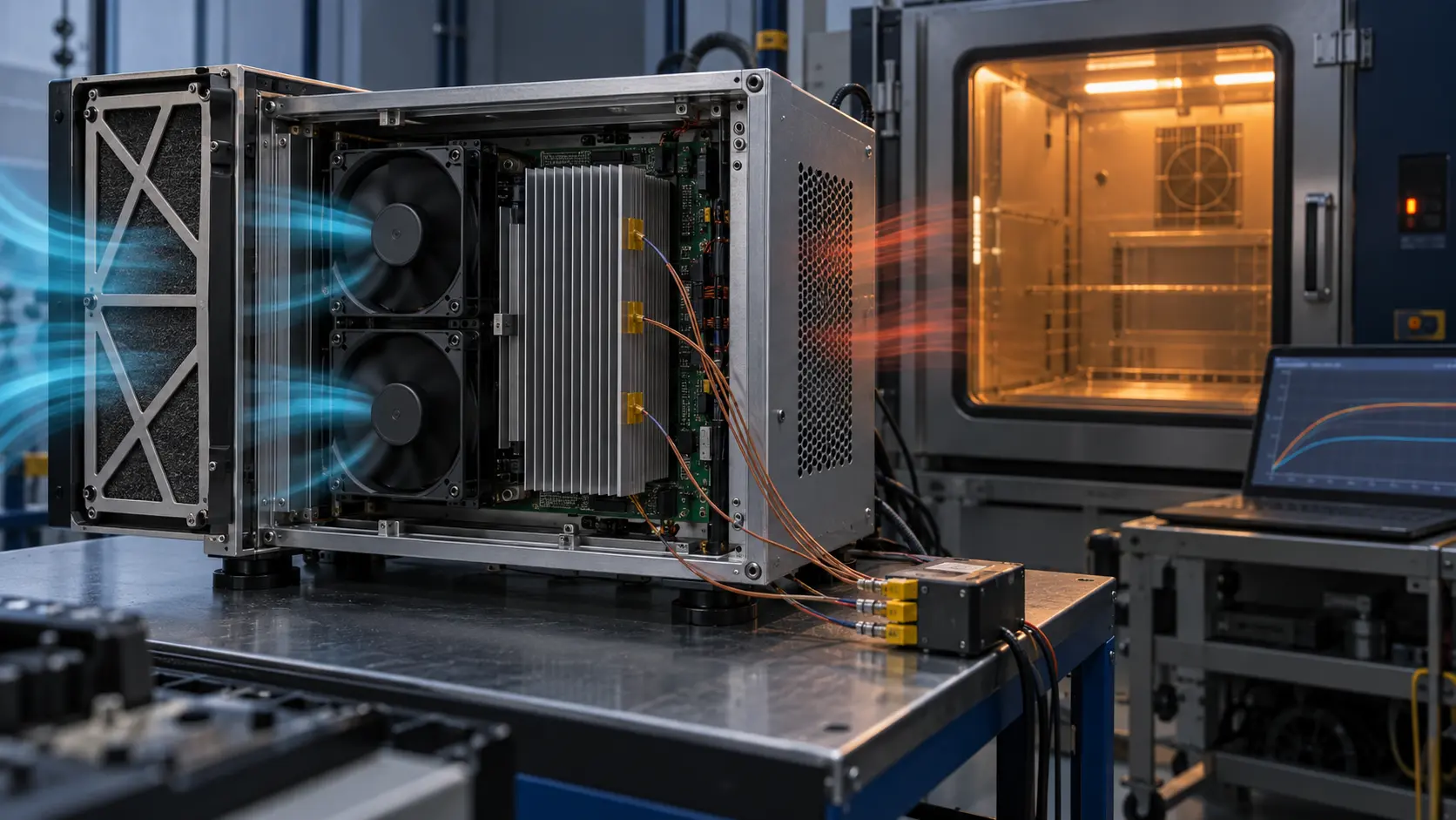
Thermal margin is the distance between the measured result and the product's acceptance limit after credible adverse conditions are included. For an electronics enclosure, that often means the highest expected ambient, maximum intended heat dissipation, the installed cover and cable routing, a realistic service-state intake restriction, and the lowest fan command or supply condition that the control strategy permits.
These conditions do not take turns. High ambient removes temperature headroom while a loaded filter moves the system curve upward; a reduced command can then leave less installed airflow exactly when the heat load is highest. A normal RPM signal alone cannot prove that the heat source is receiving useful air.
AMCA's fan-selection guidance starts with required flow and system pressure rather than free-air flow, and it cautions that the installed arrangement should reflect the tested arrangement to avoid system-effect surprises. Use that as the first principle: validate the complete installed air path, not an ideal fan on a bench.
Define the Worst Case as a Testable Stack
Write the adverse conditions as a stack that can be built, measured and repeated.
Do not label a test simply 'worst case' without defining its inputs. The useful question is: which combination is physically credible for the product's duty cycle, environment, controls and service condition? A short startup transient, a hot-weather full-load mode and a partially loaded filter may deserve different tests rather than one vague maximum.
ASHRAE energy guidance uses a midlife filter pressure-drop concept when calculating certain fan systems. That is an HVAC context, not a compliance rule for a compact enclosure. Its transferable lesson is still valuable: clean-filter data alone is not a service-life design condition. Agree the representative restriction condition for the actual product and document it.
| Variable | Define before the test | Record with the result |
|---|---|---|
| Heat load | Maximum credible dissipation and energized modules | Input power, load state and dwell time |
| Ambient | Installation envelope or chamber setpoint | Ambient and inlet-air temperature |
| Air path | Cover, cables, baffles, grille and filter condition | Photos, configuration and differential pressure |
| Fan control | PWM floor, voltage tolerance and fault logic | PWM, supply voltage, RPM and current |
| Acceptance | Named hotspot and permitted limit | Sensor locations, peak and stabilized values |
Interactive Model: Stack the Conditions
Move the credible stressors together to see why a clean, full-speed result is not the same as margin.
This screening model combines relative ambient, restriction, command and heat-load effects into a qualitative margin indicator. It intentionally does not calculate a product temperature or a fan catalogue rating. Its purpose is to make the test stack visible before the chamber slot or prototype is booked.
Use the outcome to decide which combination needs a measured system curve, a thermal test, a control review or a geometry change. Production acceptance must come from the representative assembly and its agreed limits.
Why RPM Does Not Close the Case
RPM reports rotor speed, not necessarily delivered flow through the critical heat path.
A fan can report an expected speed while its operating point has shifted because the filter, grille, heat sink, outlet or bypass path changed. The useful evidence is a set of linked measurements: fan command, voltage, RPM, current, pressure where it matters, inlet temperature and the named hotspot temperature.
The fan laws explain why speed is influential but incomplete. For a similar fan, pressure capability changes approximately with speed squared and power approximately with speed cubed. That makes higher RPM a costly response to an avoidable restriction. It also does not correct air that bypasses the heat sink or recirculates at the outlet.
If the control deliberately allows a lower PWM command at certain temperatures, that command belongs in validation. Confirm sensor placement, hysteresis and fail-safe behavior before claiming that nominal full-speed performance protects the application.
Build a Minimum Validation Matrix
The goal is not to test every theoretical combination. It is to cover the credible decisions that can change the acceptance result.
Begin with a normal reference condition so changes have a baseline. Add a high-ambient test at the intended maximum heat load, then a service-state airflow-path test. Finally, run the combined representative condition where the product's real duty cycle supports it. Allow enough dwell time for the measured hotspot to stabilize, and define what stabilization means in the procedure.
Keep one controlled change per comparison whenever possible. If a sample fails only after a cover and filter are added, measure the path pressure difference and inspect for bypass or recirculation before requesting a higher-RPM fan. The first corrective action may be a plenum, seal, open-area change, larger filter face or a revised control threshold.
For every run, preserve the assembly configuration. A thermal result is hard to reuse if it does not state which fan, revision, filter, grille, sensor locations, voltage and control command were installed.
- Normal reference: normal ambient, intended assembly and commanded operating mode.
- High ambient: maximum credible ambient with maximum intended thermal load.
- Service path: agreed filter or restriction condition with the installed cover and outlet hardware.
- Control floor: lowest permitted command, voltage or thermal-control mode relevant to operation.
- Combined condition: credible stack of the variables most likely to reduce margin.
- Evidence pack: temperatures, command, voltage, RPM, current, pressure, dwell and configuration photos.
Correct the Constraint, Then Revalidate
The best remedy is the one that improves the actual operating point while respecting noise, power, cost and service life.
Start by removing avoidable resistance and bypass. Increase effective intake area, give the filter a plenum, improve transitions, seal the intended heat-sink path and prevent exhaust recirculation. These changes can improve useful airflow without treating acoustic and power penalties as an afterthought.
If the path is already credible, choose a fan or blower from the required operating point at the agreed adverse condition. Compare its pressure-flow behavior, power, acoustics, signal interface and life requirement at that point, rather than comparing maximum CFM or shut-off pressure alone.
A custom sample review can turn this into a practical plan. Share the heat load, environment, available space, enclosure layout, intake and outlet details, restriction data, voltage, control logic, noise limit and acceptance temperature. The deliverable should be a sample and validation plan, not an unsupported promise.
Engineer FAQ: Worst-Condition Fan Validation
A credible thermal claim names the application condition, the evidence and the limit.
Q: What is thermal margin for a fan-cooled enclosure? A: It is the measured distance between the named hotspot result and its allowed limit under a defined application condition. It is not the fan's free-air CFM or its maximum static-pressure value.
Q: Must every enclosure use a dirty-filter test? A: No. Test the credible service condition. A sealed, filterless product needs a different adverse-path definition than a filtered industrial cabinet. The important point is to document the condition that the product will actually see.
Q: Can I validate with RPM and a single temperature sensor? A: Usually not. RPM confirms speed, while one sensor can miss the critical hotspot. Record the control command, voltage, RPM, current, relevant pressure and temperatures at named locations.
Q: Should I always choose the highest-speed fan to gain margin? A: No. First verify geometry and bypass. Higher speed can add pressure capability, but it also affects noise, power and bearing stress. Select from the installed operating point.
Q: What can MEGA Tech review before a sample build? A: Send the thermal load, target limit, ambient envelope, enclosure drawing, filter and heat-sink data, space, voltage, PWM or signal requirement, noise target and duty cycle. We can help translate them into a practical fan and validation plan.