Three Components Sit Between the Fan Curve and the Electronics
The datasheet P-Q curve is measured on a bare fan. The fan you install behind a finger guard, an inlet filter and a 40 mm clearance gap is not that fan.
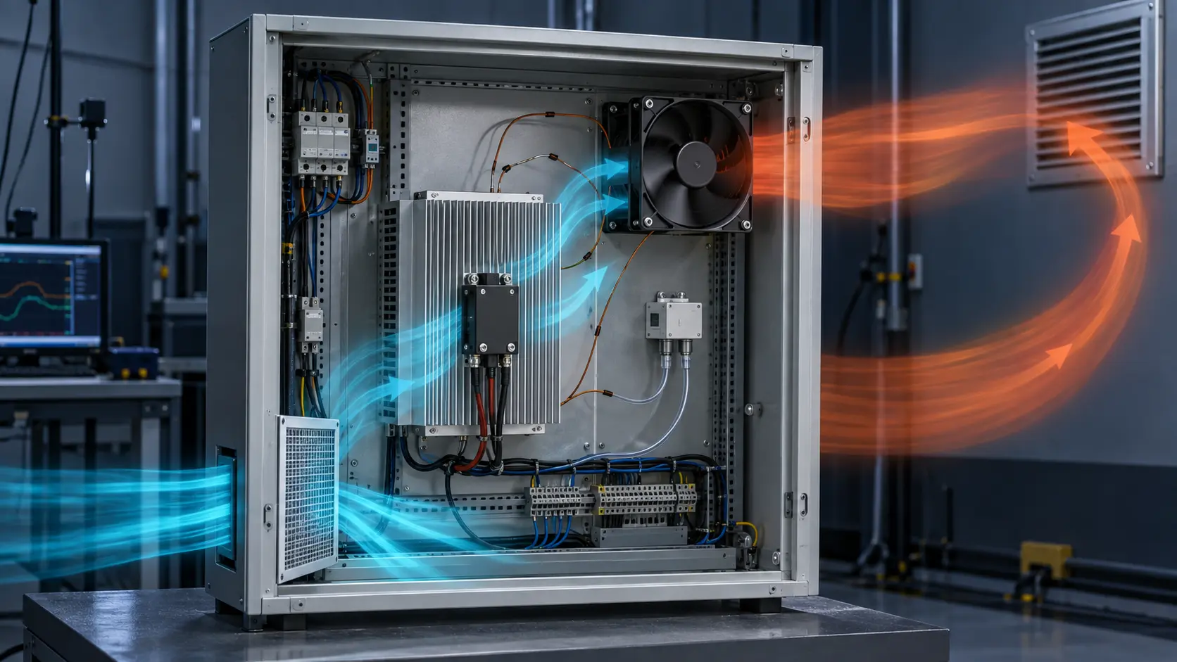
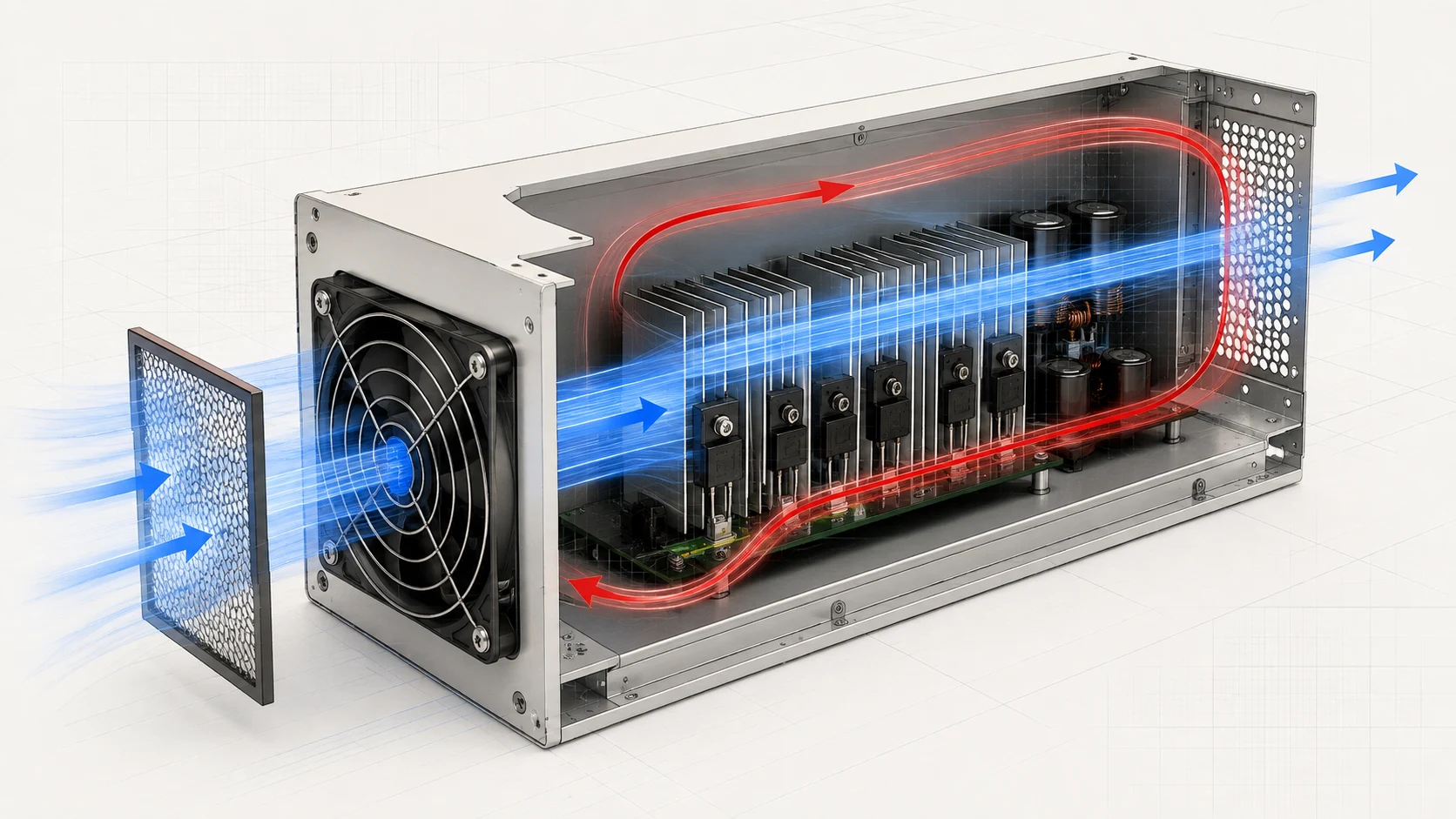
Every catalogued fan curve is measured in a laboratory arrangement: the fan bolted to a test duct or a measurement plate, no grille, no filter media, no wall anywhere near the inlet. The moment the same fan goes into an enclosure, three installation components start taxing its performance. A finger guard adds obstruction right at the blade tips, where the flow velocity is highest. An inlet filter adds a resistance element that starts small and grows for its whole service life. And the clearance distances around the inlet and outlet decide how much of the fan's own pressure survives as useful flow.
None of these losses is exotic. Each one can be estimated from geometry before a single part is purchased, and each one is regularly left out of fan selections. The consequence repeats across projects: the fan that met the airflow requirement on paper delivers 10 to 25 per cent less in the cabinet, the temperature margin that justified the design quietly disappears, and the fix is a higher speed setting - which raises noise and power consumption, per the fan laws.
This guide puts numbers on all three components. Section by section it covers the safety standard that shapes every guard, the open-area arithmetic that separates a good guard from a throttling plate, first-order pressure estimates you can run in a spreadsheet, filter sizing against the loaded condition rather than the clean one, and the clearance distances that keep the fan curve honest. The worked example in the middle ties them together: one 120 x 38 mm fan, four intake configurations, four operating points.
The Guard Must Pass a 12 mm Test Finger
Guard geometry is not a style choice. The openings are sized by an international test probe, and everything else follows from them.
The benchmark is IEC 61032 test probe B: a jointed steel finger, 12 mm in diameter and 80 mm long, applied to every opening with a force of 10 N. The test, which fan safety standards such as UL 507 and IEC 60335-2-80 incorporate, is simple to state - the probe must not touch the blades - and it sets the first hard constraint on the guard: no gap may admit a 12 mm cylinder. Guards are also commonly rated IP2X against access to hazardous parts using this same probe.
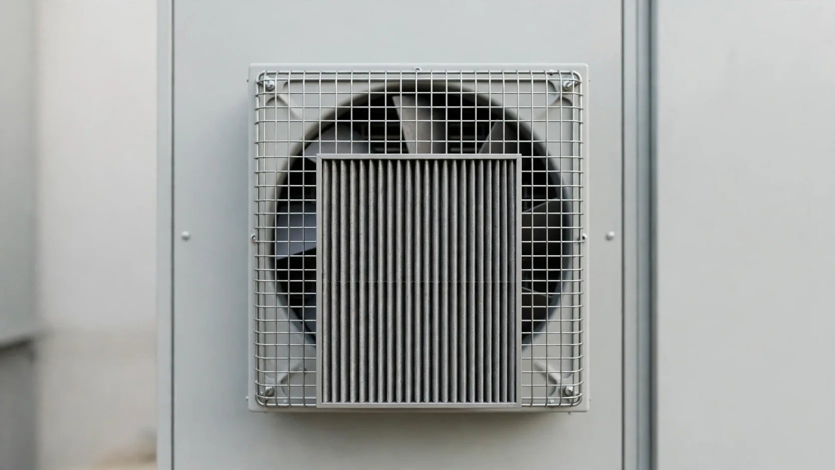
That constraint immediately explains the two families of guard seen on electronics cooling fans. Wire guards, made of rings and radial ribs of roughly 1 to 2 mm steel wire, keep the openings large but the obstruction thin. Plate guards - punched, perforated or slotted sheet - meet the finger test with a dense pattern of small holes or slits, which is geometrically easier but puts far more solid material into the airstream. A third option, a close-spaced mesh, exists mainly for tamper resistance and, as shown below, costs the most airflow.
Sanyo Denki publishes the comparison directly: guard shapes with a smaller open area increase airflow resistance, reduce maximum airflow and raise noise at the same fan speed - and if the speed is then raised to recover the lost airflow, noise and power rise further. The engineering conclusion is to treat the guard as a flow component first and a cosmetic panel second: maximise open area within the finger-test constraint, keep wire edges rounded, and validate the fan with the actual guard installed.
Open Area: Geometry You Can Calculate Before You Buy
The single most predictive number for a guard is its open-area ratio, and you can compute it from the drawing.
Open-area ratio is the fraction of the guard face that is hole rather than material. For a wire grid it is the square of the clear spacing divided by the pitch squared. For a punched plate it is the hole area times the hole count divided by the face area. Both calculations take two minutes and a ruler, and they order the candidates before any vendor data arrives.
Take three declared geometries on the face of a 120 mm fan. A wire guard of 1.5 mm wire on a 12 mm square pitch has an open-area ratio of (12 - 1.5) squared over 12 squared, which is 0.77 - about 77 per cent open. A punched plate with 5 mm diameter holes on a 7 mm square pitch has pi times 2.5 squared over 49, which is 0.40 - about 40 per cent open. A slotted plate with 4 mm slits on a 10 mm pitch in one direction is 40 per cent open as well, and because long slits present long sharp edges to the blade wake, vendors place them last for both airflow and noise.
The table below carries the calculation and the qualitative ordering that Sanyo Denki and guard manufacturers such as EAO publish for the same families. Note what the arithmetic says about the punched plate: to reach the same 77 per cent open area as the wire guard, its holes would have to grow to about 7 mm diameter on the same 7 mm pitch - at which point the 12 mm test finger constraint starts to bite from the other side, because the ligaments between holes shrink to nothing.
| Guard geometry | Declared dimensions | Open area (calculated) | Airflow and noise impact at equal speed (vendor-published ordering) |
|---|---|---|---|
| Wire rings and ribs | 1.5 mm wire, 12 mm square pitch | 77 per cent | Small loss, small noise rise - the default for electronics cooling |
| Punched plate, round holes | 5 mm holes, 7 mm square pitch | 40 per cent | Noticeable loss, medium noise rise; chamfer hole edges if used |
| Slotted plate | 4 mm slits, 10 mm pitch | 40 per cent | Highest loss and highest noise rise of the three; use only when required |
First-Order Pressure Estimates for Guards
Open area converts into pressure loss through one line of arithmetic, good enough to size the problem before measurement.
For a guard that occupies the fan face, the face velocity is the airflow divided by the fan's area, and the loss scales with the square of that velocity times an obstruction coefficient. A 120 mm fan moving 120 cubic metres per hour presents a face velocity of 2.95 metres per second over its 0.0113 square metre area. Applying first-order coefficients - about 0.8 for a rounded wire grid at 77 per cent open area, about 4.4 for a punched plate at 40 per cent, about 7 for a slotted plate - gives 4 Pa for the wire guard, 23 Pa for the punched plate and 37 Pa for the slotted plate.
Treat these as screening estimates, not measurements: the coefficients depend on wire shape, hole chamfer and plate thickness, and a vendor with test data will beat the arithmetic. What the estimates establish is the scale of the decision. The difference between a wire guard and a punched plate on one inlet is roughly 19 Pa in this example - which, as the worked example below shows, is worth more delivered airflow than an entire fan-speed tier. Sanyo Denki's published comparison says the same thing from measurement: guard shape changes maximum airflow and noise visibly, not marginally.
Two second-order effects are worth noting. First, the guard sits in the blade-tip region where local velocity is highest, so its loss concentrates exactly where the fan is least able to afford it - one reason a close-fitting punched plate hurts more than the open-area ratio alone suggests. Second, the rotating blade wake passing the guard wires generates a tonal noise component at the blade-passing frequency; rounded or aeroformed wire profiles reduce it, and vendors note that chamfered hole edges serve the same purpose on plates.
| Guard | Open area | Assumed loss coefficient | Estimated pressure loss |
|---|---|---|---|
| Wire grid, rounded 1.5 mm wire | 77 per cent | 0.8 | about 4 Pa |
| Punched plate, 5 mm holes | 40 per cent | 4.4 | about 23 Pa |
| Slotted plate, 4 mm slits | 40 per cent | 7.0 | about 37 Pa |
Inlet Filters: Clean Pressure Is Not the Design Point
A filter is the only component in the intake stack whose resistance is guaranteed to grow. Select the fan against the filter it will become, not the filter you install.
Filter pressure drop has two numbers, and the second one is the design number. Cabinet filter-fan assemblies are typically quoted at 3 to 8 Pa of clean resistance at their rated flow, with a clogged filter adding 15 to 25 Pa or more - and filtration suppliers report initial media resistance of 15 to 25 Pa at 1.5 metres per second for low-grade panel media, growing with dust load. At the HVAC scale the same pattern appears magnified: a MERV 13 filter at its rated 2000 CFM moves from roughly 0.4 inches of water gauge (about 100 Pa) clean to 1.0 inches (about 250 Pa) at recommended change-out. The ratio is what matters: the loaded condition costs two to four times the clean pressure, and it is the condition the fan lives in for most of its service interval.
Filter resistance also scales with the square of face velocity, because the filter is a flow resistance like any other. Halving the face area at constant airflow quadruples the filter's pressure contribution. This is why stuffing a small washable pad directly against a fan inlet - a common retrofit - costs far more airflow than the same media spread over a larger plenum face upstream. Give the filter area and it costs little; starve it and it behaves like a second system resistance stacked on the first.
Monitoring closes the loop. Field guidance for filtered installations recommends warning at 70 per cent of the filter's final pressure and critical action at 90 per cent, with differential-pressure trend rates - a rise faster than 30 per cent per week signals an abnormal dust event rather than normal loading. A two-port differential gauge across the filter costs little and converts an invisible degradation into a scheduled task. The mechanics of loading and its effect on the fan's operating point are treated in depth in the BESS filter loading guide; the arithmetic here is the same for any cabinet.
| Source and context | Clean | Loaded / final | Change-out guidance |
|---|---|---|---|
| Cabinet filter-fan assembly at rated flow (filter-fan vendor) | 3 to 8 Pa | 15 to 25 Pa or more | Replace on differential pressure, not calendar |
| Low-grade panel media at 1.5 m/s face velocity (filtration supplier) | 15 to 25 Pa | grows with dust load | Size the fan for the loaded value |
| MERV 13 at 2000 CFM (HVAC sizing reference) | about 100 Pa (0.4 in wg) | about 250 Pa (1.0 in wg) | Warning at 70 per cent of final, critical at 90 per cent |
Clearance: The Distances That Protect Fan Performance
Fan curves assume unobstructed air on both faces. Industry installation guidance puts a distance on that assumption.
An obstruction close to the fan inlet starves the impeller: the flow cannot accelerate into the blade region, the effective system resistance rises, and the fan delivers less than its curve promises. The same obstruction on the outlet side generates back-pressure turbulence and discharge losses. Fan-industry installation guidance is consistent across sources: allow a gap of at least one fan diameter between the fan intake and nearby obstructions, and at least one diameter at the outlet before a wall or duct turn, while noting that even then performance can fall short of the rating.
One diameter is the conservative number, and in electronics packaging it is often unaffordable. Practical guidance for tight installations settles on a minimum of one third of the fan diameter between the fan face and the nearest obstruction - a coil, a filter, a wall - on either side; one manufacturer of cooling installations quotes 35 per cent of impeller diameter as its optimum at both inlet and outlet. For a 120 mm fan the minimum is therefore about 40 millimetres of free air on each face, with 120 millimetres as the fully conservative figure. Backward-curved centrifugal blowers, which turn the flow 90 degrees, need more room at the inlet - around half an impeller diameter - and less at the outlet, around 0.3 diameters.
Wall proximity has a second, quieter cost. An outlet blowing into a nearby surface forms a recirculation loop that re-ingests heated air, so the enclosure's effective ambient rises even though the airflow number looks acceptable; the diagnosis path for that failure mode is in the hot-air recirculation guide. Where two fans sit side by side, one fan manufacturer's installation guidance recommends a centre-to-centre spacing of at least 1.5 impeller diameters so the inlets do not rob each other. Neither effect appears in any datasheet; both appear in field measurements.
| Situation | Rule | At a 120 mm fan |
|---|---|---|
| Axial fan inlet or outlet to nearest obstruction (conservative) | at least 1 fan diameter | 120 mm or more |
| Axial fan inlet or outlet, practical minimum | at least 1/3 of fan diameter | 40 mm or more |
| Axial fan, manufacturer-quoted optimum | 35 per cent of impeller diameter | 42 mm |
| Backward-curved centrifugal inlet / outlet | 0.5 / 0.3 impeller diameters | for a 200 mm wheel: 100 / 60 mm |
| Two axial fans side by side | 1.5 diameters centre to centre | 180 mm |
A Worked Example: One Fan, Four Intake Configurations
The pieces assemble into one operating-point calculation. Every input below is declared; every output follows from the fan and system equations.
Take a 120 x 38 mm DC frame whose typical catalogued curve gives 150 cubic metres per hour of free delivery and 90 Pa of maximum static pressure - both numbers representative of the 120 x 38 class, and both to be verified against the specific datasheet before use. Approximate the curve as a parabola: pressure equals 90 times one minus (flow over 150) squared. The enclosure alone - grilles, internal path, exit - is measured or estimated at 25 Pa when 120 cubic metres per hour passes through it, a resistance coefficient of 25 divided by 120 squared.
Now dress the intake. The wire guard from the table above adds 4 Pa at the reference flow. A punched-plate guard adds 23 Pa instead. A washable media panel behind the guard, sized over a generous face, adds about 10 Pa clean and 30 Pa loaded - consistent with the vendor ranges cited earlier. Each configuration is a new system curve, and the operating point is its intersection with the fan curve.
The results, computed from the two equations, are the whole argument of this guide in four numbers. The bare cabinet delivers 125 cubic metres per hour. Adding the wire guard costs 3 per cent. Substituting a punched-plate guard costs 11 per cent. Adding a loaded filter behind the plate costs 22 per cent against the bare selection - and that is the condition the fan will sit in for weeks at a time. A selection made on the bare number only, with no pressure margin, has no reserve left when the filter loads; the fan must run faster, converting a filtration problem into a noise and power problem.
| Intake configuration | System pressure at 120 m3/h | Delivered airflow | Change versus bare |
|---|---|---|---|
| Bare cabinet | 25 Pa | 125 m3/h | - |
| Wire guard (77 per cent open) | 29 Pa | 122 m3/h | -3 per cent |
| Punched-plate guard (40 per cent open) | 48 Pa | 111 m3/h | -11 per cent |
| Punched-plate guard plus loaded filter | 78 Pa | 98 m3/h | -22 per cent |
Reading the Operating-Point Shift on the P-Q Plane
The figure below is the worked example drawn to scale. Four system curves, one fan curve, four intersections.
Three features of the plot deserve attention. First, the four system curves all pass through different points at the same 120 cubic metres per hour reference - 25, 29, 48 and 78 Pa - because each accessory adds a separate, additive resistance at that flow. Second, the intersections slide down the fan curve's steep upper region, where a small pressure change buys a large flow change; that is why a 53 Pa accessory stack costs 22 per cent of flow rather than a proportional 53 per cent. Third, the loaded-filter point sits at a lower static pressure than the fan's maximum, but the airflow has fallen below the 120 cubic metres per hour requirement - the fan is not in trouble, the budget is.
This is the same intersection arithmetic as any P-Q curve reading, with one discipline added: draw the system curve for the worst legitimate condition, not the day-one condition. If the intake stack must include a filter, the design point is guard plus loaded filter plus cabinet. If it must also include an EMI honeycomb or heat-exchanger core, add its measured resistance at the same reference flow the same way.
Speed headroom is the remaining lever. A four-wire fan with PWM control can recover the lost flow by raising duty, and the fan laws say power rises with roughly the cube of speed - so recovering 22 per cent of flow by speed alone costs tens of per cent more fan power and audible noise. Selecting a frame with pressure margin at the fouled point is cheaper than buying the recovery with RPM.

Inlet, Outlet and Wall Clearance in Practice
Clearance is free performance: it costs millimetres in the layout, not watts in the bill of materials.
Apply the rules at layout time. On the intake side, keep at least a third of the fan diameter - 40 millimetres for a 120 mm frame - between the guard face and the nearest solid: a bracket, a cable bundle, a filter frame, a partition. On the exhaust, one diameter before the first obstruction keeps discharge losses and the recirculation risk down; where the layout cannot afford it, a short duct or a diffuser cone recovers part of the loss. Behind a wall-mount fan, the same one-diameter rule applies to the surface the exhaust faces.
Two layout details reward attention. A filter or guard mounted more than the minimum clearance from the fan face loses measurably less than one hard against it, because the flow has room to redistribute before it reaches the blades - the obstruction still costs pressure, but it stops concentrating in the blade-tip region. And an intake facing a wall at less than one diameter behaves like a partially blocked inlet even with nothing visibly in the way; the guidance is explicit that performance can fall short of rating even at a full diameter.
Centrifugal and mixed-flow blowers follow the same logic with different constants - roughly half an impeller diameter clear at the inlet and 0.3 at the outlet for backward-curved wheels - because their flow turns inside the scroll. When a custom fan is requested, state the clearance the enclosure can offer; the answer changes which frame class fits, and it is much cheaper to move a bracket in CAD than to discover a starved inlet in validation.

Noise: The Second Invoice From Guards and Filters
Every accessory that adds pressure also adds sound, through two different mechanisms.
The first mechanism is direct: guard wires and hole edges sit in the fastest, most turbulent part of the flow, and the rotating blade wake chopping through them radiates a tonal component at the blade-passing frequency - for a nine-blade fan at 3000 RPM, 450 hertz and its harmonics. Vendor guidance for guards and plates alike points at the same mitigations: rounded wire profiles, chamfered hole edges, and maximum open area so the local velocities stay low.
The second mechanism is indirect and usually larger. When accessories cost airflow, the common recovery is speed - and per the fan laws, acoustic power rises with roughly the fifth power of speed for the flow-generated component, so a modest RPM increase buys a clearly audible noise increase. Sanyo Denki's guard comparison states the consequence directly: raising speed to offset guard losses raises both noise and power. A fan selected with margin at the fouled operating point simply never takes that penalty.
The noise guide covers measurement and specification in depth. For this guide the rule is short: specify the noise limit at the fouled condition, with the guard and filter installed, at the speed the fan will actually run in service.
Validation: Measure the Stack, Not the Fan
Every number in this guide is checkable in one afternoon with the real parts and an anemometer.
The validation sequence is short. Assemble the real intake stack - guard, filter, fasteners, the actual clearance - on the real enclosure. Measure delivered airflow with the real-enclosure method, not free-air. Fit a clean filter and record the differential pressure across it; run or accelerate the loading and record the pressure at the warning threshold. Compare the measured operating point with the selection estimate; a gap of more than about 10 per cent means a system resistance was missed, and the usual suspects are the filter face area, a bent bracket in the inlet path, or an outlet closer than the table above allows.
Record three numbers in the design file: delivered airflow at the fouled condition, differential pressure across the filter at its warning threshold, and the fan duty cycle or speed needed at that condition. Those three numbers are the acceptance criteria for the next production batch, and they are exactly what a fan manufacturer needs to reproduce the result on a replacement or a second-source frame.
Guard verification has its own checklist item: present the IEC 61032 probe B - or have it applied by the test house - to the installed guard, not to a datasheet claim. Mounting hardware deforms, plastic guards warp near heat, and a guard that passed on the bench can fail on the cabinet after a thermal cycle.
What MEGA Tech Does With the Loss Budget
Fans are selected at the operating point, and the operating point includes everything in this guide.
MEGA Tech is a custom cooling-fan manufacturer. We select DC axial and backward-curved centrifugal fans by operating condition, not by part number, and we treat the guard, the filter and the clearance as part of the condition. When you brief us, we work from the fouled working point: airflow and static pressure with every intake accessory in place, the filter at its change-out pressure rather than its clean value, the clearance the enclosure can actually offer, the voltage window, the noise limit at that operating point and the life assumption behind the bearing choice.
What we need from you is the stack: the guard drawing or its open-area ratio if it is known, the filter media and its clean and final pressure at the design flow, the clearance dimensions, and the airflow-temperature target with its tolerance. If the filter is not yet chosen, say so - the selection then carries an explicit pressure reserve instead of a silent one. Samples are validated on your unit, in your stack, at your ambient; we do not certify the enclosure, the EMI assembly or the safety file, and we do not supply enclosure panels, filters or controllers.
The boundary keeps the responsibility clear: your team owns the enclosure, the filter specification and the safety compliance of the assembly; we own the fan - its curve, its bearing life, its control behaviour and its fit to the working point you declare. Send the operating point with the accessories included, and the sample that arrives is selected for the fan you are actually buying.
Engineer FAQ
Six questions that decide most guard, filter and clearance reviews.
Q: How much airflow does a finger guard really cost? A: A rounded wire guard at 70 to 80 per cent open area costs a few per cent at typical face velocities - about 3 per cent in the worked example; a punched or slotted plate at 40 per cent open area costs an order of magnitude more. Compute the open area from the drawing and treat anything below 50 per cent as a selection-level penalty.
Q: Do I size the fan for the clean or the loaded filter? A: For the loaded filter. Clean-versus-loaded pressure typically differs by a factor of two to four, and the fan spends most of its service life in between but trending toward loaded. If speed control exists, the clean condition is handled by lower duty - never the reverse.
Q: What clearance does a 120 mm fan need? A: A practical minimum of one third of the diameter - 40 mm - on each face, with one full diameter as the conservative target and one diameter before any outlet obstruction. Side-by-side fans need 1.5 diameters between centres.
Q: Does the guard belong on the intake or the exhaust? A: Wherever the hazard is. Performance-wise the guard costs least where local velocity is lowest; on a pressure-side application that is often the exhaust face. Safety requirements, not preference, decide where hands or tools can reach.
Q: Can I recover the lost airflow with a faster fan setting? A: Yes, and the fan laws price it: power roughly with the cube of speed and flow-generated noise with about the fifth. Recovering a 22 per cent deficit by speed is the most expensive solution on the table; pressure margin at selection is the cheapest.
Q: Which standard governs the guard openings? A: IEC 61032 test probe B - a 12 mm, 80 mm jointed finger applied at 10 N - incorporated by fan safety standards such as UL 507 and IEC 60335-2-80, and the basis of an IP2X access rating.
Questions for a Design Review
Bring these to the review with the guard and filter drawings on the table.
- What is the guard's open-area ratio, computed from the drawing - and does the 12 mm test probe B pass on the production part, not the prototype?
- What are the filter's clean and final pressure drops at the design airflow, and is the fan selected at the final value?
- What clearance exists on each fan face in the actual layout - guard-to-wall, outlet-to-obstruction, fan-to-fan - and against which rule from the table?
- What is the total intake-stack resistance at the reference flow: cabinet plus guard plus filter plus anything else that shares the opening?
- What duty cycle or speed does the fan need at the fouled condition, and does the acoustic specification hold at that speed?
- What three numbers - fouled airflow, filter warning pressure, service duty - will the next design revision be validated against?