Pressure Drop Is a Path Problem
The fan does not overcome one restriction. It overcomes every loss between ambient air and the final exhaust condition.
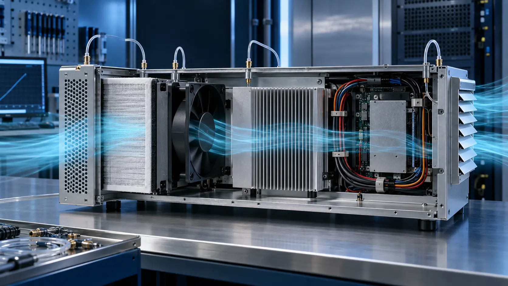
An enclosure pressure budget lists the losses in the order air sees them: intake opening, grille, filter, fan guard, ducts or turns, heat sink, cable blockage, outlet louvre and any leakage or bypass that changes the intended path. At a chosen airflow, the system loss is the sum of those component losses plus installation effects. That total belongs on the same axes as the fan P-Q curve.
ASHRAE describes system pressure loss as the sum of losses imposed by the air-distribution elements on both inlet and outlet sides of a fan, including resistance, leakage and system-effect factors. That principle applies directly to a compact electronics enclosure even though its individual pressures are much smaller than an HVAC system.
The budget is not a promise that every early estimate is exact. It is a design tool that exposes which unknown deserves measurement first. If the filter accounts for most of the expected loss, selecting a bigger fan before obtaining the filter curve is guesswork. If an undersized grille dominates, improving open area may reduce noise and power more effectively than raising RPM.
Make the First Budget at the Required Flow
Pressure loss has no meaning without an airflow and a measurement condition attached to it.
Start from the airflow required by the thermal calculation, not the fan's free-air CFM. At that target flow, collect supplier pressure-drop curves for filters and heat sinks where available, estimate grille and duct losses from geometry, and label every estimate with its source and uncertainty. A loss quoted at another airflow cannot simply be copied without checking the curve or its stated method.
For turbulent restrictions, pressure loss often rises approximately with the square of airflow. That makes small increases in demanded flow expensive: a tighter path can push the operating point left on the fan curve much faster than intuition suggests. Use the relationship as a first-pass model, then replace the largest uncertain terms with representative measurements.
Keep clean and service-state budgets separate. Filter loading, contamination and manufacturing variation change the system curve. A fan that meets the clean-condition target can miss the thermal requirement later even though RPM remains normal.
| Path element | Input to request or measure | What can change it |
|---|---|---|
| Intake grille / guard | Open area, geometry or measured ΔP | Panel thickness, nearby wall, fouling |
| Filter | ΔP curve at flow; clean and service state | Media, effective area, dust loading, bypass |
| Heat sink / channel | ΔP curve or representative test | Fin pitch, shroud sealing, flow distribution |
| Cables / brackets / turns | Geometry estimate, CFD or test | Assembly routing, bends, unplanned obstructions |
| Exhaust louvre | Open area and ΔP | Back pressure, screen, rain louvre, recirculation |
Interactive Model: Find the Biggest Restriction
Move the individual losses to see why the best correction is usually the largest avoidable term, not automatically a faster fan.
The sliders use relative pressure units so the model does not imply a catalogue rating. They show a budget at one fixed screening flow. Use the result to ask which component needs a measured curve, larger effective area, a straighter path or a different fan family.
A real budget must be revisited after a geometry change because changing one restriction can change flow distribution and the pressure drop of the others. The point is to make assumptions visible before the sample arrives, then replace them with evidence.
Fix Geometry Before Spending Fan Pressure
More static pressure can be necessary, but it should not compensate for an avoidable restriction or bypass path.
First check whether all intake air uses the intended filter area. A narrow opening, poor gasket or fan mounted directly against a filter can create a non-uniform loading pattern. More filter face area, a plenum, an improved seal or a less restrictive approved media can reduce loss without increasing fan speed.
Next check the high-loss internal elements. A heat sink only cools when air crosses its fins; a bypass gap can make enclosure airflow look healthy while the heat sink sees little flow. A shroud or baffle can improve useful flow, though it may add its own pressure loss. Validate the complete path rather than assuming any single change is beneficial.
Only after the restriction chain is credible should you move to a higher-pressure fan, a different blower type or a series arrangement. Higher speed changes pressure, power, noise and bearing stress together. The correct choice comes from the operating point and the full acceptance test, not max static pressure alone.
Validate the Budget in the Representative Enclosure
A pressure budget becomes engineering evidence when the largest terms are checked on a built assembly.
Install the intended cover, filter, grille, gasket, heat sink, cables and outlet hardware. Record voltage, PWM command, RPM, current, inlet temperature, hotspot temperature and pressure at defined planes. Keep the measurement locations fixed when comparing candidates or layout revisions.
Measure across the components that dominate the preliminary budget, particularly the filter and heat sink path. A differential-pressure result is most useful when both taps are on named planes and the fan command, flow condition and filter state are recorded with it. Do not compare a clean-filter pressure reading with a loaded-filter thermal test and call it a trend.
Repeat at the realistic degraded condition. For a filtered cabinet, agree a service-state pressure drop or representative loading condition. For an outdoor device, include the expected grille, screen and contamination condition. The acceptance decision should state both the normal and degraded operating point.
- Target airflow and thermal requirement defined before selection.
- Each loss tied to a curve, calculation, measurement or clearly labelled estimate.
- Largest uncertain terms measured on the representative assembly.
- Clean and degraded filter or path conditions tested separately.
- Voltage, RPM, pressure, temperature and power recorded together.
- Approved geometry preserved in the sample and production record.
Engineer FAQ: Enclosure Pressure-Drop Budgets
A budget is valuable only when the assumptions are visible and the final operating point is verified.
Q: Can I add the maximum pressure drops from every component? A: No. Add each component's pressure drop at the same target airflow and stated condition. A maximum or shut-off number from a different flow condition does not belong in the budget.
Q: Should I budget clean or dirty filter pressure drop? A: Both. Use clean data for the baseline and the agreed service-state or final condition for thermal margin. Do not assume one universal multiplier because media, dust and face velocity differ.
Q: Is the biggest pressure-drop component always the first thing to change? A: Usually investigate it first, but confirm whether it is necessary for safety, filtration or thermal uniformity. The best correction may be more effective area, a better transition, a different approved component or a fan with a more suitable curve.
Q: Does a higher-static-pressure fan solve every restrictive enclosure? A: No. It can recover an operating point, but it also changes noise, power and reliability. It cannot make bypassed air cool a heat sink or correct a misleading measurement plane.
Q: What can MEGA Tech review for a custom fan sample? A: Share the heat load, target flow or pressure, enclosure drawing, intake and exhaust details, filter and heat-sink data, available space, voltage, controls, noise limit and expected environment. We can use the restriction chain to define and validate a practical sample.