The Fan May Be Moving Air Around the Problem
A fan can report normal RPM, make a strong exhaust jet and still feed warmed air back to its own intake.
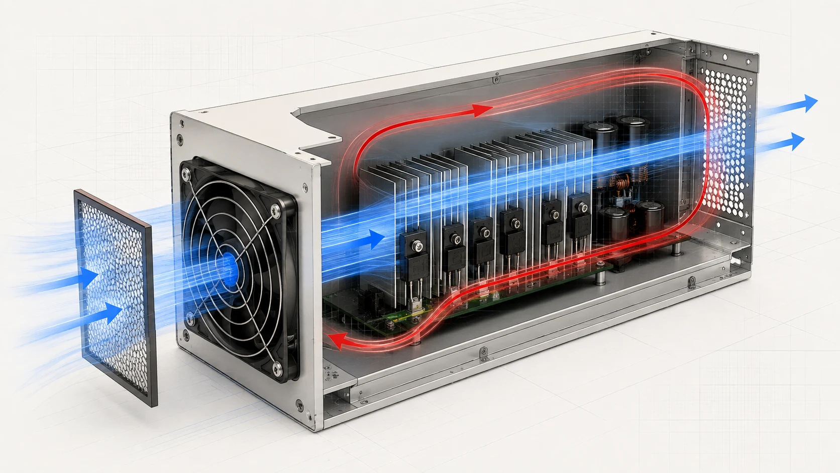
Recirculation occurs when discharged air returns to the intake region before it has mixed with cooler ambient air. Internal bypass is the related enclosure problem: air enters and exits through the shortest available route while the heat sink or hot component receives too little of it. Both can make free-air CFM and an apparently normal fan signal misleading.
The diagnostic clue is a temperature pattern, not one number. Compare ambient air, fan inlet air, exhaust air and the named hotspot under the same load. If the intake is materially warmer than ambient or the hotspot changes strongly when a temporary barrier is added, investigate the path before specifying a faster fan.
AMCA identifies obstructions, uneven inlet flow and adverse inlet or outlet arrangements as system effects that reduce installed fan performance. In compact electronics, the same principle appears as a nearby wall, louvre, cover, cable bundle, exhaust plume or gap that changes where air really travels.
Separate External Recirculation From Internal Bypass
The corrective action depends on which loop is stealing the useful temperature difference.
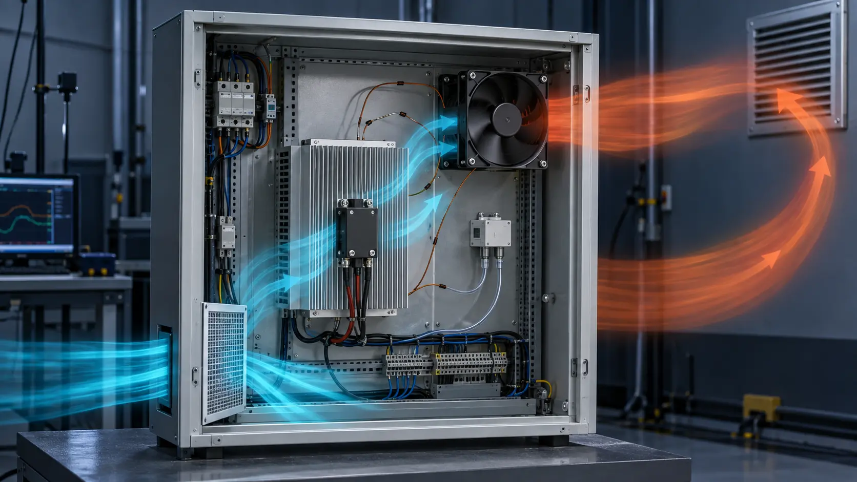
External recirculation happens outside the enclosure. The exhaust plume is drawn toward a nearby intake because openings are too close, a wall redirects the discharge, a weather hood traps the plume or multiple cabinets interact. The inlet temperature rises even when the internal path is reasonably sealed.
Internal bypass happens inside. A fan can draw from a nearby opening, gap or low-resistance void instead of across the heat sink. The enclosure may exchange air rapidly while the hot component sees weak local velocity. A simple temporary baffle or a smoke visualization test can reveal the route, but production decisions need repeatable temperature and pressure evidence.
Do not assume that intake fan versus exhaust fan is a universal answer. Dust, IP goals, filtration, natural buoyancy, component placement and service access all matter. The design goal is a defined path from the coolest practical intake through the heat source and to an exhaust that cannot easily return.
| Observation | Likely mechanism | First check |
|---|---|---|
| Fan inlet air warmer than room ambient | External exhaust recirculation | Opening spacing, nearby wall, louvre and plume direction |
| Hotspot remains high but exhaust is cool | Internal bypass or poor heat-sink flow | Gaps, shroud, fan-to-sink alignment and cable blockage |
| RPM rises with little hotspot improvement | System resistance or recirculation | Pressure path, intake temperature and operating point |
| Temperature changes after removing cover | Cover-induced short path or restriction | Repeat test with documented cover and seals |
Interactive Model: Trace the Air That Reaches the Hotspot
Switch between layouts to see why the fastest route is not always the useful route.
This is a qualitative path model. It does not predict temperature, fan CFM or pressure. Use it to decide what to inspect and where to place thermocouples, smoke, pressure taps or an air-temperature probe before a sample review.
A layout that removes the orange return loop may still need a pressure-budget check. A barrier that creates a longer path can improve heat-sink flow, but it can also add restriction. Verify the complete operating point after every geometry change.
Run a Four-Temperature Check Before Changing the Fan
A small, repeatable measurement plan usually reveals more than comparing nominal CFM values.
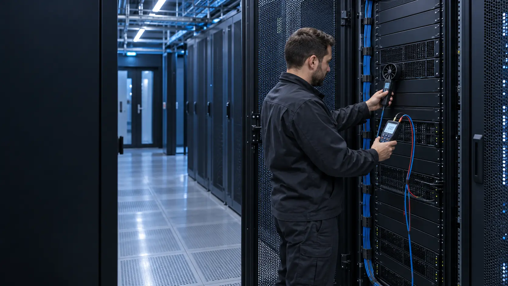
At a steady, documented load, record room ambient away from the exhaust plume, fan inlet temperature, exhaust temperature and the critical hotspot. Record fan command, voltage, RPM and the cover, filter and louvre configuration at the same time. Move the ambient probe carefully: it must not sit in the discharge jet or directly against a cold wall.
Repeat with one temporary diagnostic change, such as spacing the cabinet from a wall, extending the exhaust direction, blocking a known internal gap or moving the intake probe plane. A meaningful change in inlet or hotspot temperature points to the path that deserves engineering work. It does not by itself prove a final geometry or guarantee compliance.
Forum discussions around electrical cabinets repeatedly return to the same practical concern: an exhaust near the top can remove buoyant heat, but it only works well when the cabinet has a defined replacement-air path and the exhaust cannot be pulled straight back toward the intake. Treat the installation as part of the cooling system.
- Define the load and wait for the hotspot to stabilize.
- Measure ambient away from the cabinet discharge.
- Measure intake air near the fan or intake plane without blocking it.
- Measure exhaust air and the named hotspot at fixed locations.
- Record PWM, voltage, RPM, current and all path hardware.
- Change one path feature at a time and repeat the same dwell.
Fix the Path Before Paying for RPM
The most durable correction often gives the air a better route instead of demanding more speed from the fan.
For external recirculation, separate intake and exhaust openings, redirect the discharge, add a suitable hood or duct, and check the installation against the real surrounding wall and adjacent equipment. The aim is cooler inlet air, not merely a stronger-looking exhaust jet.
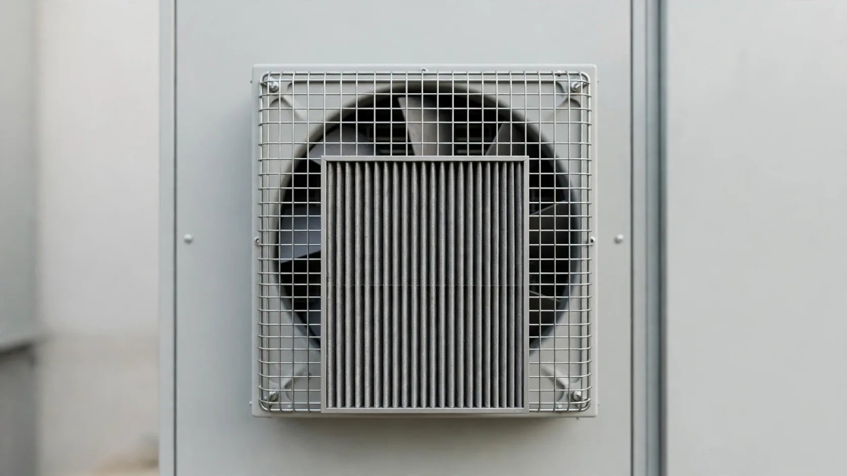
For internal bypass, seal unintentional gaps, use a plenum or shroud to guide flow across the heat sink, increase useful intake area and keep cable routing out of the high-velocity path. Check that filters, guards and rain louvres are included in the pressure budget, not added after fan selection.
Only then reconsider fan pressure or speed. AMCA notes that increasing speed to overcome system effects increases energy and mechanical stress. For a DC axial fan, higher speed can also raise acoustic output and move the control strategy away from its intended duty. Select from the installed operating point.
Engineer FAQ: Enclosure Recirculation
The useful result is evidence that the critical component receives cooler, purposeful airflow.
Q: Does a high exhaust temperature prove the enclosure is cooling well? A: No. It can indicate heat removal, but it does not show whether the hotspot is protected or whether the warmed discharge is returning to the intake. Measure the hotspot and inlet temperature too.
Q: How close can an intake and exhaust be? A: There is no universal electronics-enclosure distance. The risk depends on flow, opening geometry, nearby surfaces, wind, louvres and cabinet arrangement. Use a representative test or airflow study rather than copying a generic spacing number.
Q: Can a faster fan fix recirculation? A: Sometimes it changes the result, but it can strengthen the unwanted loop, add noise and power, or leave the bypass untouched. Diagnose the route first.
Q: Is smoke testing enough? A: Smoke can reveal a path qualitatively. Combine it with stable temperatures, control settings and, where useful, pressure measurements for a defensible validation result.
Q: What should I send MEGA Tech for a cooling-path review? A: Share the enclosure drawing, component heat loads, intake and exhaust details, nearby installation surfaces, filter and louvre data, voltage and control method, allowable temperatures, noise target and expected environment. We can help turn the path into a sample and validation plan.