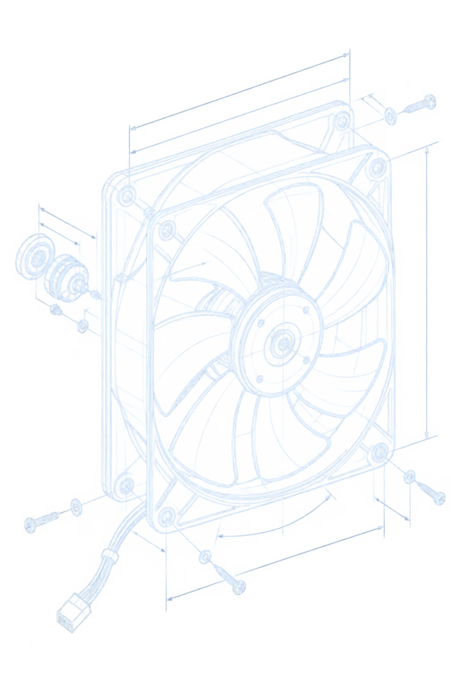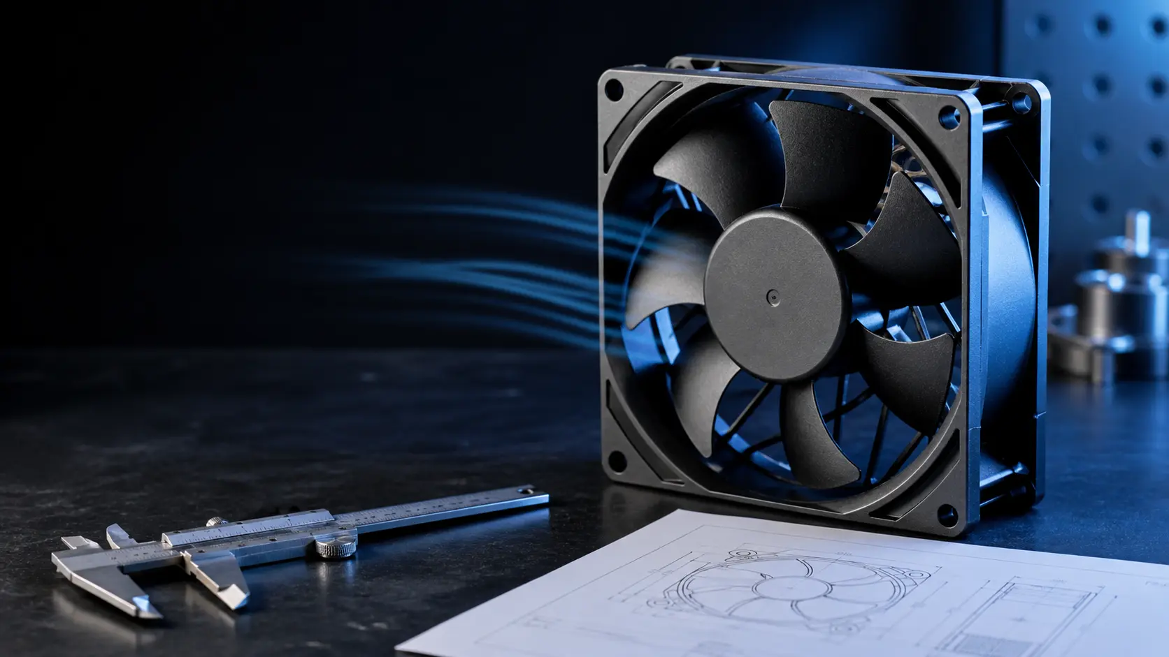
The same footprint is not the same fan
Two 80 x 80 x 25 mm fans with the same mounting holes can differ by 40 % in airflow at the pressure the cabinet actually imposes, by 8 dB(A) in sound power, and by a factor of five in bearing life. The footprint is the easiest thing to match and the least informative.
A replacement fan is usually requested because the original part is expensive, has a long lead time, or is being discontinued. The instinct is to search by size: same frame, same thickness, same hole pattern, same connector. That search answers one question — will it fit — and none of the questions that decide whether the machine cools. Fan curves, bearing systems, motor drives and acoustic behaviour are set independently of the housing, which is why two fans with identical envelopes are not interchangeable.
The failure mode this produces is quiet. The replacement spins, moves air, and passes a bench glance. Months later the same cabinet trips on temperature in a summer afternoon, or the operator notices a tone that the original never had, or the tach signal never appears and the controller logs a fault. None of these show up at the moment of the swap, and all of them trace back to a selection that compared dimensions instead of operating points.
The reverse is also true, and it is the opening this method relies on. A fan with a different frame size can be a valid replacement if the mounting can be adapted and the operating point, electrical interface and life class match or exceed the original. What has to be equivalent is the duty the fan performs, not the box it arrives in.
This guide defines the checkpoints a replacement must match, the arithmetic of the operating point, the electrical interface traps, and a five-step validation protocol that ends with the sample running in the real assembly. It is the method behind any credible replacement programme — and the reason a supplier should ask for the duty before offering a part number. Related reading: fan lifetime and bearings.
Read the duty before the catalogue
A replacement is defined by the duty the original fan performs in the machine, not by the original part number. Five measurements describe that duty, and every one of them is cheaper than a wrong sample.
Start from the machine, not the fan. What is the airflow path: where does air enter, what does it pass over, where does it exit? What is the temperature of the air at the fan inlet at worst case — not room ambient, but the preheated air inside the assembly after the electronics have been running? What resistance does the path impose — filters, grilles, heat sinks, cable bundles? These determine the operating point the replacement has to reach.
If the original fan is still available, its part number gives the reference curve. If it is not, the operating point can still be established from the machine: measure the temperature rise across the electronics at a known ambient, estimate the airflow from the original specification if one exists, or measure air speed at the vent with an anemometer and correct for outlet area. A differential pressure tap across the inlet filter adds the resistance figure that most projects never write down and always need.
Write the duty down as numbers before contacting any supplier: required airflow at the measured static pressure, maximum noise at the operator position, available supply voltage and its tolerance, the control interface actually wired (three-wire with tach, four-wire with PWM, or two-wire thermistor speed control), and the environment — ambient range, orientation, dust load, salt fog exposure. This list is the specification. A supplier who receives it can propose candidates; a supplier who receives only a part number will propose a footprint.
The custom cooling fan RFQ inputs guide covers this specification work in depth. The short version: every hour spent defining the duty saves a sample cycle later, because the candidates arrive pre-filtered against the real requirements instead of against the catalogue's most similar geometry.
| Item | What to record | Why it selects or rejects a candidate |
|---|---|---|
| Operating point | Required airflow at the static pressure the real path imposes | The candidate's curve must pass at or beyond this point with margin |
| Inlet air temperature | Worst-case air temperature at the fan inlet, not room ambient | Density and the fan's own temperature rating shift with it |
| Noise limit | Sound power or sound pressure at a stated distance and condition | A candidate 6 dB(A) louder changes the product, not just the fan |
| Electrical interface | Supply voltage window, current budget, PWM frequency range, tach output | Wrong interface logic logs faults even when cooling works |
| Environment | Ambient range, orientation, dust, salt fog, vibration, altitude | Bearing system, IP treatment and lubricant follow the environment |
The five checkpoints a replacement must pass
Fit is one check among six. Each checkpoint either matches, exceeds, or fails — and a candidate that fails any single one is not a replacement, whatever the rest of the datasheet says.
Checkpoint one is mechanical: frame dimensions, thickness, mounting hole pattern and position, inlet and outlet opening areas, and the vent geometry around it. A fan with smaller open area than the original loses flow no matter what its curve says, because the extra restriction sits in series with the system. Checkpoint two is electrical: voltage window including the ride-through the machine must survive, running and stall current against the drive budget, and connector pin-out.
Checkpoint three is the operating point, and it is the one this guide spends a section on: the candidate's certified curve must cross the system curve at an airflow equal to or better than the original's, with the filter loaded. Checkpoint four is acoustics: sound power level overall, plus the tonality — a candidate with a strong blade-passing tone at a different frequency can measure the same overall dB(A) and still sound noticeably worse to an operator.
Checkpoint five is life and environment: bearing type and L10 at the real winding temperature, IP treatment if the path demands it, lubricant class for the ambient, and any altitude derating the site requires. Each checkpoint has a pass rule. Equal is a pass. Exceeding is a pass. Slightly below on a checkpoint that the machine never exercises is a judgement call that belongs to the engineer who owns the thermal budget — not to the datasheet comparator.
| Checkpoint | Parameter | Source of truth |
|---|---|---|
| 1. Mechanical | Frame, thickness, hole pattern, inlet/outlet open area | Mechanical drawing, not the catalogue photo |
| 2. Electrical | Voltage window, running and stall current, connector and pin-out | Datasheet electrical table and the machine's wiring diagram |
| 3. Operating point | Certified P-Q curve crossing the measured system curve, filter loaded | ANSI/AMCA 210 style certified data at the real supply voltage |
| 4. Acoustics | Sound power at the operating point, tonality note | Datasheet acoustic data plus a like-for-like listening test |
| 5. Life and environment | Bearing type, L10 at real temperature, IP class, salt fog severity class | Datasheet life curve at real temperature, IEC 60068 series test reports |
Match the operating point, not the free-air rating
The free-air number on the catalogue cover is the one value a fan can never deliver in a real machine. A replacement is proved by where its curve crosses your system curve.
Every fan curve starts at a maximum: free airflow at zero pressure, shut-off pressure at zero flow. A real machine sits somewhere in between, at the point where the fan curve crosses the system resistance curve. Two fans with the same free-air rating can cross the same system curve at materially different airflows, because the curve shape — how steeply pressure falls with flow — decides who wins at mid-range.
The comparison that matters is therefore arithmetic on two curves. Take the original fan's curve and the candidate's curve, both at the real supply voltage. Take the system curve — measured, or estimated from the filter pressure drop and the vent velocities. Mark where each fan curve crosses the system curve. The candidate qualifies on airflow only if its crossing point is at or beyond the original's, at the worst-case conditions from section two: loaded filter, hot inlet air, minimum supply voltage.
Worked example. The system curve is P = 0.00382 Q² (Pa against m3/h), which puts the original fan's crossing at 120 m3/h against 55 Pa with a loaded filter, and the machine's thermal budget needs 110 m3/h at that state. Candidate A is a mid-pressure fan: 210 m3/h free air, 100 Pa shut-off. Its curve crosses the system curve at 128 m3/h — a 6.7 % margin, acceptable. Candidate B is a low-pressure type with a flashier free-air rating of 230 m3/h but only 52 Pa of shut-off pressure; against the same resistance its curve crosses at 104 m3/h — below the requirement at exactly the state that matters. Candidate B has the bigger number on the box and fails the duty; Candidate A has the smaller number and passes.
Margin discipline matters as much as the crossing point. A replacement selected with zero margin sits at the requirement on paper and below it in reality, because catalogue curves are nominal and production fans vary. Reputable manufacturers state aerodynamic tolerance in their datasheets; where it is not stated, treat anything under 10 % airflow margin at the worst-case point as unproven. Related reading: how to read a fan P-Q curve.

Electrical and control compatibility is a specification, not a pin count
The connector fitting is the smallest part of electrical compatibility. Speed control behaviour, tach output and fault signalling decide whether the machine runs or logs alarms.
Three-wire fans expose a tachometer output, four-wire fans take a PWM speed command, and the two families are not plug-compatible in behaviour even when the pins line up. Four-wire fans follow the Intel 4-wire PWM specification in the industry at large: nominal PWM frequency 25 kHz, with the duty cycle commanding speed and the tach output delivering two pulses per revolution. A controller designed for that interface expects a fan that follows it; a candidate whose PWM range or tach behaviour differs will cool correctly and still report faults.
Check the PWM duty-to-speed response, not just the pin-out. Some fans hold a minimum speed at low duty and cut off below it; others run to zero. Some emit a tach signal that stalls when the fan is commanded off, others keep pulsing. If the machine's firmware maps tach frequency to rpm and alarms on a stall, a replacement with a different low-duty behaviour can put a healthy cooling system into a fault state. The tach, RD and airflow fault validation guide walks the fault-path tests.
Stall and startup current deserve a line each. A candidate with a higher stall current can brown out a marginal supply during spin-up, which resets the controller and looks like an unrelated bug. Where the original fan had a soft-start or a controlled current ramp, the replacement must match it or the supply must be re-checked at minimum input voltage with maximum load.
Two-wire thermistor-controlled fans carry their own trap: the speed curve is a function of temperature built into the fan. A replacement with a different thermistor curve will run faster or slower than the original at the same temperature, changing both cooling and noise with no fault signal at all. If the machine used a two-wire speed-controlled fan, either match the speed-temperature curve explicitly or convert the interface to external PWM control as part of the replacement.
| Fan interface | What the controller expects | What a wrong replacement does |
|---|---|---|
| 3-wire + tach | 2 pulses per revolution, stable output at operating speed | Different pulse count makes firmware read 1.5x or 0.5x the true rpm |
| 4-wire PWM | 25 kHz nominal command, duty sets speed, tach feedback | Non-standard PWM range runs the fan at the wrong speed or alarms at low duty |
| 2-wire thermistor | Speed follows a temperature curve built into the fan | Different curve cools quietly wrong — no fault, just drift |
| Locked-rotor alarm (RD) | Alarm line releases when the rotor stalls | Missing RD on a replacement removes the only stall detection the machine has |
Life and environment equivalence: temperature, dust and salt
A replacement that moves the same air can still fail years earlier if its bearing system, lubricant or ingress treatment does not match the environment the original was chosen for.
Bearing life is quoted as L10 — the hours by which 10 % of a population may be expected to have failed — and it is quoted at a reference temperature. The rule of thumb that governs every comparison: L10 roughly halves for every 10 C rise in lubricant temperature. A replacement quoted at 50 000 hours at 40 C is not equivalent to an original quoted at 50 000 hours at 25 C; at the same real inlet temperature the second fan outlives the first by more than two to one. Convert both quotes to the machine's real inlet temperature before calling them equal. The bearing lifetime guide covers the conversion arithmetic.
Bearing type is a system choice, not a spec-sheet word. Sleeve bearings are quiet and inexpensive but sensitive to orientation and high ambient; ball bearings carry higher temperature and horizontal-shaft mounting with more noise; fluid dynamic bearings combine long life with low structure-borne noise. A like-for-like replacement keeps the bearing class unless the duty analysis shows the original was over- or under-specified — in which case say so explicitly and validate the change.
Environment checkpoints follow the same logic. Where the original fan had an IP rating for dust and splash, the replacement needs the same class verified by test, not claimed by analogy — IEC 60068-2-68 dust and IEC 60529 water ingress are testable facts. For coastal or chemically loaded sites, salt fog severity is ordered in IEC 60068-2-52, and the severity class the original survived is the class the replacement must demonstrate. Altitude adds a derating question: air density falls roughly 10 % per 1 000 m, and fans rated near their limit at sea level lose their margin at height.
What datasheets hide: tolerance, derating and tone
Three properties rarely appear on the comparison line and each has changed a replacement decision: aerodynamic tolerance, acoustic tonality, and the difference between a tested value and a typical one.
Aerodynamic tolerance is the first. Catalogue curves are nominal; production fans scatter around them. Established manufacturers state the tolerance — airflow at a given pressure, or the whole curve band — and a careful comparison uses the bottom of the band, because that is what the machine sees on a bad day. Where no tolerance is published, the honest comparison treats the curve as unverified until a sample is measured, which is one more reason the validation protocol in the next section is not optional.
Acoustic tonality is the second. Overall sound power can match while the character differs: a blade-passing tone at a frequency the housing resonates, or a motor whine the original did not have. Products with operator proximity — medical devices, lab instruments, office equipment — are judged by people, and people hear tones before they hear broadband level. A like-for-like listening comparison at the real operating speed, in the real housing, catches what the dB(A) line hides.
The third is the difference between typical and guaranteed. Some datasheets mark performance values as typical; some state minimum guaranteed values; a few state both. A replacement selected on typical values carries a hidden risk the original may not have had. Where the datasheet is silent, ask in writing — the answer itself is informative about how the candidate's production is controlled.
None of these three require new measurement capability. They require reading the datasheet the way an auditor would, and asking the supplier the questions the document avoids. Related reading: fan noise in the real enclosure.
The five-step sample validation protocol
Paper comparison ranks the candidates; only a sample in the real assembly proves the replacement. Five steps, each with a pass rule, and the sequence matters.
Step one, baseline the original. Before the original fan is removed, record the machine's thermal state at worst case: temperatures at fixed points across the electronics, noise at the operator position, current draw, tach rpm, and the filter condition. Without a baseline, the replacement's results have nothing to be compared against.
Step two, thermal comparison. Fit the replacement sample and repeat the identical measurement at the identical worst-case state — loaded filter, hot inlet, minimum supply voltage. Pass rule: no monitored point hotter than baseline by more than the measurement uncertainty, and every point still inside the component derating budget. One degree of drift at a single sensor is not noise; it is the signature of a slightly smaller operating point.
Step three, acoustic comparison. Same positions, same conditions, plus a listening check by someone who knows the product. Pass rule: overall level no higher, and no new tone an operator could name. Step four, electrical and control compatibility: spin-up current, PWM response across the full duty range, tach frequency against firmware expectation, and any RD or stall alarm behaviour. Pass rule: the controller logs no new faults across a full duty sweep.
Step five, endurance. Run the machine through a thermal cycle profile representative of the field — at minimum, a hot soak, a cold start, and repeated on-off cycling — with the filter loaded, and re-check step two's temperatures at the end. Bearings reveal themselves early when they are wrong; lubricant problems show as noise and current drift within the first hundreds of hours, not the first thousands. A replacement that passes all five steps in the delivered assembly is validated; one that passes only the bench has not been tested.
| Step | What is measured | Pass rule |
|---|---|---|
| 1. Baseline | Temperatures, noise, current, rpm on the original fan at worst case | Recorded and archived before removal |
| 2. Thermal | Same points with the replacement, filter loaded, hot inlet | No point hotter than baseline beyond uncertainty |
| 3. Acoustic | Same positions plus a listening check at real speed | No higher level, no new audible tone |
| 4. Electrical | Spin-up current, PWM sweep, tach and alarm behaviour | No new controller faults across full duty range |
| 5. Endurance | Thermal cycles and on-off cycling with filter loaded | Step 2 temperatures still hold at the end |
Engineer FAQ: cooling fan replacement
Short answers to the questions that arrive with a replacement request. Each one expands on a section above.
Q: Can I replace a fan with a different frame size? A: Yes, if the mounting can be adapted and all five checkpoints pass — the footprint is not the specification.
Q: The replacement has a higher free-air CFM. Is it better? A: Not necessarily. Only the crossing point with your system curve decides; a lower-pressure curve can deliver less air at the real resistance.
Q: Do I need PWM if the original had PWM? A: Yes, if the controller commands speed. Match the PWM frequency range and duty response, and verify tach behaviour across the full sweep.
Q: The catalogue life is longer than the original's. Is that enough? A: No. Convert both L10 values to the real inlet temperature; every 10 C rise roughly halves the life.
Q: Can I validate on a bench instead of the machine? A: No. Bench results miss the system curve, the acoustics of the housing and the controller's fault logic. Validate in the shipped assembly.
Q: What if no datasheet states a tolerance? A: Treat the curve as unverified, and let the sample measurement in step two set the real value before committing.
Questions for a design review
Take these to the review with the original fan's curve and the measured system resistance on the table.
A replacement programme is a small design review with a tight scope. These questions close the gaps that produce field surprises, and every one of them can be answered before samples are ordered.
- What airflow does the original deliver at the real system pressure with the filter loaded, and what is the thermal budget's minimum?
- What is the inlet air temperature at worst case, and have both L10 quotes been converted to that temperature?
- Has the candidate's curve been checked at minimum supply voltage, not just nominal?
- Does the candidate's PWM frequency range, duty response and tach behaviour match what the controller's firmware expects?
- Is the acoustic comparison done in the real housing, including a listening check for new tones?
- What aerodynamic tolerance does the candidate's manufacturer state, and was the comparison made at the bottom of the band?
- Which IP class and salt fog severity does the original carry, and what test report does the replacement offer for the same class?
- Does the validation plan cover all five steps in the assembly that ships, including the endurance re-check?