A Fan RFQ Is an Engineering Boundary, Not a Shopping List
A frame size and a maximum CFM figure are not enough to predict whether a sample will cool the real product.
The useful question for a custom cooling-fan request is: what must the completed air path prove in the product? AMCA selection guidance starts with application type, air density, required flow and pressure. For compact equipment, that same decision must also include the filter, grille, heat sink, cable routing, nearby walls and the fan's electrical interface.
A requirement that only says '92 mm, 24 V, high airflow' invites rework. It leaves the supplier to guess the system resistance, thermal target, installed geometry, signal behavior and environment. A better brief makes every assumption visible, then separates catalogue data, engineering estimates and measurements from the real enclosure.
The 12 Inputs That Make a Request Selectable
Group the request into thermal duty, air path, physical integration, electrical interface, environment and acceptance evidence.
Not every project begins with every number. A preliminary request can use a clearly labelled engineering estimate, such as a heat-balance airflow target. The important practice is to label it as an estimate and identify the measurement that will replace it before production approval.
For example, a 600 W heat-to-air load with a 12 K allowed air-temperature rise gives a first estimate of about 0.041 m3/s, or 87 CFM, using Q = P / (rho x cp x DeltaT) at 1.2 kg/m3 and 1,005 J/(kg K). That is not a fan selection. Filter loading, heat-sink resistance, leakage, altitude, inlet temperature and installation effects can move the final operating point materially.
| Group | Inputs to provide | Why it changes the sample |
|---|---|---|
| Thermal duty | Heat-to-air load, allowable temperature rise, inlet temperature and target hotspot | Sets the first airflow and temperature-validation target |
| Air path | Required flow or local velocity, pressure estimate, filter, grille, heat sink and duct restrictions | Defines the actual operating point instead of free-air CFM |
| Mechanical | Frame, thickness, mounting, inlet/outlet clearance, airflow direction and service access | Prevents an electrically correct fan from creating bypass, noise or installation interference |
| Electrical | Voltage range, operating and startup current, PWM or voltage control, FG/TACH, RD/alarm, connector and cable | Ensures the fan starts, reports and recovers correctly with the product controller |
| Environment | Temperature, humidity/condensation, dust, water, corrosion, orientation, vibration and duty cycle | Defines the bearing, sealing and qualification questions for the selected configuration |
| Acceptance | Test fixture, limits, measurement locations, sample quantity and change-control rule | Turns the sample into a repeatable release decision |
Interactive Model: Find the Missing Requirement Before the Sample
Click each group to see the minimum input and the validation question it unlocks.
This is a planning tool, not an automatic selector. A fan curve, system curve and representative test still decide whether a candidate meets the installed duty.
The Air Path Must Be Described as Installed
Pressure losses and system effects are usually where a seemingly suitable fan sample fails.
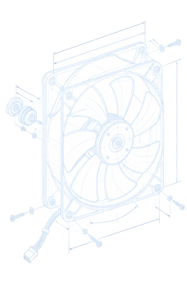
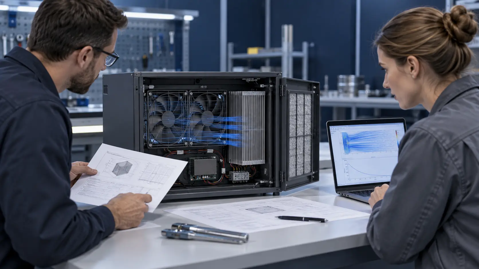
Give the supplier a drawing, photos or a representative mock-up whenever practical. Identify the intake and exhaust openings, nearby walls, grille open area, filter media, heat-sink fins, cable bundles, duct transitions and intentional or accidental bypass gaps. AMCA notes that disturbed inlet or discharge flow can reduce installed performance, increase noise and add vibration even when the fan itself meets its laboratory rating.
If pressure data are not yet available, do not invent a universal allowance. Start with component pressure-drop data, a simple test fixture or CFD where appropriate, then validate the completed path. The best supplier input is not a maximum static-pressure number; it is the required airflow at a stated pressure, voltage, temperature and installation condition.
Lock the Electrical and Environmental Details Early
A mechanically suitable replacement can still fail at power-on, under control loss or after environmental exposure.
State the voltage range at the fan connector, not only the nominal supply. Include startup current and duration, normal current at the intended operating point, PWM frequency and logic level where applicable, FG/TACH pulse definition, RD or alarm behavior, connector family, pinout, cable length and routing. A normal RPM signal proves rotation, not installed cooling, so fault behavior must be reviewed alongside pressure and temperature evidence.
Environmental requirements need the same discipline. Specify the actual inlet temperature range, humidity or condensation exposure, dust or water boundary, vibration direction, mounting orientation, expected daily duty and service interval. An enclosure IP requirement does not automatically become a fan IP rating, and a bearing-life figure is meaningful only with its stated temperature, speed, orientation and load assumptions.
Approve the Sample Against a Written Test Matrix
The sample is useful when it closes an engineering decision, not when it merely spins on an open bench.
Before the sample arrives, agree the states to test: nominal load, credible high ambient, the intended restrictive condition such as a filter or grille, startup at the low permitted connector voltage, control loss or restart where relevant, and the defined fault state. Record the test configuration and sensor locations with the result so that the next sample or production lot can be compared honestly.
At minimum, log fan-terminal voltage, command, RPM/FG, current, relevant pressure, inlet and exhaust temperatures, named hotspot temperature, noise where it matters and the result of the defined alarm or restart behavior. If an acceptance value is an estimate, record the plan and ownership for converting it into a measurement.
- Freeze the drawing, direction, connector, cable and control definition together with the selected fan.
- Test the installed resistance and mechanical boundary, not a clean fan alone.
- Separate thermal-duty validation from any system safety or compliance claim.
- Use the same matrix after a material fan, controller, filter or enclosure revision.
Engineer FAQ: Writing a Custom Cooling-Fan Request
These questions prevent a request for quotation from becoming a sequence of avoidable sample changes.
Q: Can we request a fan before the system pressure is known? A: Yes, if the request labels the pressure as unknown and provides the geometry, restrictions and thermal target. Treat the first candidate as an engineering screen, then measure or estimate the real resistance before approval.
Q: Is maximum CFM sufficient for a comparison? A: No. Compare airflow, pressure, voltage, speed and power at the same operating point and installation condition.
Q: What is the most useful file to attach? A: A dimensioned enclosure drawing or clear photos that show the complete intake-to-exhaust path, plus the electrical connector and target thermal measurements.
Q: Should we specify a bearing type first? A: Specify the temperature, speed, orientation, contamination, vibration and life objective first. The selected bearing construction must then be supported by model-specific evidence.
Q: What makes a sample production-ready? A: A written configuration and test record showing that the selected fan meets the agreed installed thermal, airflow/pressure, electrical, acoustic and fault-behavior conditions.