
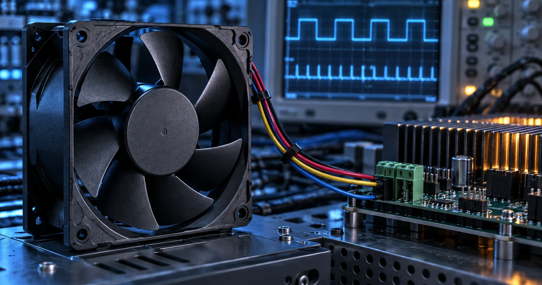
A fan that spins is not necessarily a fan that is controlled correctly
A DC fan interface carries four separate engineering questions at once: will it start at the lowest supply voltage, what does the control signal actually mean, how much current does the start take, and does the delivered airflow still meet the thermal need at the installed pressure.
The most common field failure is not a failed fan. It is a fan running at a speed nobody commanded, on a rail nobody checked, with a feedback signal that is being read as proof of cooling when it only proves rotation. A 4-wire fan's control input is not the same thing as switching its supply rail, and the two are routinely confused because both are described as PWM control.
The second failure is quieter. A controller that survives steady-state current can still collapse when several fans start together, because the start current is not the number printed on the label. Delta says so on its own approval sheets: the maximum value of the consuming current does not represent the peak value, and the peak has to be measured with an oscilloscope.
This article separates the interface into the four things that have to be specified and tested independently: the supply window, the control input, the start behaviour and the feedback signal. Each one has a number attached to it, and none of those numbers transfers from one fan model to another.
Three ways to change a fan speed, and only one of them is a control interface
A fan can be slowed by reducing its supply voltage, by switching its supply on and off, or by commanding a dedicated control input. Only the third one was designed to be commanded.
Reducing the supply voltage slows a two-wire or three-wire fan, and it works, but it moves the fan away from the point at which the vendor measured it. The start voltage is a separate figure from the operating range, and on a 12 V part it can sit at the bottom of that range. Torque falls as the voltage falls, so a fan that starts at its lowest voltage in free air may refuse to start against a loaded filter.
Switching the supply rail on and off at a few kilohertz also changes the average voltage, and it is the method that produces most of the complaints this article is about. The fan's own controller sits inside the loop being switched. Every off period removes its supply, and the gate drive, the soft-start ramp and the locked-rotor timer restart on the next on period. If the switching frequency is low enough to hear, the motor's own switching becomes audible, and the tachometer output describes a motor being restarted rather than a fan running at a speed.
A 4-wire fan separates the two functions. Pin 2 carries the rated voltage continuously and pin 4 carries a logic-level square wave that the fan's internal controller reads, so the fan's own output stage does the switching at a frequency it was designed for. The Intel specification is explicit that the trace from the controller to the fan header must carry no external pull-up or pull-down, because the pull-up resistor sits inside the fan hub.
That separation is what makes the interface worth having, and it is also what makes the pinout dangerous. Noctua warns in its PWM white paper that connecting a 12 V or 24 V supply to the control pin will damage the fan immediately. The control pin is a logic input and not a power input, and a mis-crimped harness is enough to reach it.

| Method | What changes | What the fan controller sees |
|---|---|---|
| Reduce the supply voltage | The average voltage at pin 2 falls | A supply approaching its start voltage, with torque falling as the voltage falls |
| Switch the supply rail | Pin 2 is chopped at the switching frequency | Its own supply removed and restored many times a second |
| Command the control input | Pin 4 duty cycle changes, pin 2 stays at the rated voltage | A logic-level command, with its supply undisturbed |
What the 4-wire PWM references actually specify
The Intel document is a reference for one interface family. Read what it fixes, and note what it leaves to the fan vendor.
The September 2005 revision of the Intel 4-Wire PWM Controlled Fans Specification sets the fan supply at 12 V plus or minus 5 percent, caps steady-state current at 1.5 A with 12.6 V applied in free air, and explicitly allows a start-up current spike above 1 A. It requires the fan vendor to state a minimum speed, caps that minimum at 30 percent of maximum, and requires the fan to start and run at it. It calls the speed response a continuous and monotonic function of the duty cycle, with the resulting speed within plus or minus 10 percent of the duty cycle that was asked for.
Two clauses in the same document change how a controller has to be designed. If no control signal is present at all, the fan is required to run at maximum speed, and the control input is pulled up inside the fan. An open control wire is therefore not an off switch; it is a command for full speed issued by a broken connector. The second clause is that below the stated minimum duty cycle the document defines three permitted behaviours rather than one, so the low end of the control range is a question for the fan vendor and not for the specification.
Outside that document nothing is universal. The frequency, the logic thresholds, the minimum duty cycle, the start condition and the feedback logic are properties of the individual fan. Noctua, which reproduces the Intel limits in its own white paper, gives a logic-low maximum of 0.8 V, an absolute maximum short-circuit current of 5 mA, an absolute maximum control voltage of 5.25 V, and an accepted frequency range from 21 to 28 kHz. Those are the numbers a controller has to be checked against, and they are not the same numbers for a 48 V fan.
Below the minimum duty cycle, the behaviour is not defined
A controller written on the assumption that zero percent means stopped will eventually meet a fan that disagrees.
Intel's document describes three permitted behaviours below the minimum duty cycle. A fan with the first behaviour holds minimum speed at every duty cycle below the minimum, including zero. A fan with the second also holds minimum speed for non-zero values but stops at zero. A fan with the third lets the speed fall until the current in the windings can no longer sustain commutation, and the minimum speed it publishes is also its minimum starting speed: it may continue to run below that speed, but it will not start there.
Real data sheets show all three. SANYO DENKI Technical Report No. 58 lists the 9CRH0612P6G001 with ratings at a 100 percent and a 20 percent duty cycle, gives 25 kHz as the control frequency, and then states that the speed is zero at a zero percent duty cycle for models that have no rating listed at zero, and that the speed with the control terminal left open equals the speed at a 100 percent duty cycle. The same construction appears in the manufacturer's splash-proof catalogue, where models that do list a rating at zero are singled out.
Two design consequences follow. A stop command has to be a decision the controller makes rather than an assumption about the fan: if the fan must stop for a thermal or acoustic reason, that has to be verified on the exact model. And a speed command at or below the minimum duty cycle has to be handled deliberately. If a control loop drives the duty cycle to zero to hold a temperature, it may be commanding minimum speed or no rotation, and those two have opposite thermal consequences.
The duty cycle to speed relation is not linear across its whole range either. Noctua publishes one of its own fans as the example: 2,000 RPM at a 100 percent duty cycle, about 1,100 RPM at 50 percent and 450 RPM at 20 percent. A controller that assumes a proportional relation will be wrong at both ends of the range even when the fan is behaving exactly as specified.
The operating voltage range belongs to the model number
Two fans with the same nominal voltage on the same rail can have operating ranges that do not overlap at the ends.
A 48 V fan is not a fan that needs exactly 48 V. Across the approval sheets surveyed for this article, the quoted operating range on a 48 V nominal part runs from 28.0 V to 56.0 V on one Delta model, from 36 V to 60 V on a SANYO DENKI counter-rotating model, and from 36 V to 72 V on a SANYO DENKI 172 mm model. On a 24 V nominal rail the range runs from 15 V to 30 V on one part and from 16 V to 30 V on another. A 12 V part can be quoted as 10.8 V to 13.2 V or as 5.0 V to 13.8 V.
Two numbers in that list decide whether a design works. The first is the bottom of the operating range, because a rail that dips below it during a load step may take the fan outside its published behaviour. The second is the start voltage, which is quoted separately and can sit exactly at the bottom of the range. On the Delta FFB0412VN-00 the operating range is 5.0 V to 13.8 VDC and the start voltage is 5.0 VDC, so the fan is at its starting limit precisely where the rail is at its worst.
The practical rule is to verify at the fan connector rather than at the power supply, and to do it at the extremes of the quoted range rather than at nominal. Harness drop, connector resistance and the impedance of a shared supply all sit between the converter and the fan, and in a multi-fan cabinet it is the sum of the start currents that the rail actually sees.
| Nominal voltage | Operating range from the data sheet | Example model |
|---|---|---|
| 12 V | 10.8 V to 13.2 V | SANYO DENKI 9CRH0612P6G001 |
| 12 V | 5.0 V to 13.8 VDC, start voltage 5.0 VDC | Delta FFB0412VN-00 |
| 24 V | 15 V to 30 V, and 16 V to 30 V | SANYO DENKI 9GP1224P1G001 and 9GP5724P5H001 |
| 48 V | 28.0 V to 56.0 VDC | Delta FFB1248SHE |
| 48 V | 36 V to 60 V | SANYO DENKI 9CRH0648P6G001 and 9GP1248P1G001 |
| 48 V | 36 V to 72 V | SANYO DENKI 9GP5748P5G001 |
Startup current is not the number printed on the label
A steady-state current allowance and a start-up current allowance are two different numbers, and only one of them is on the label.
Delta sets out the problem on its own approval sheet for the FFB0412VN-00, a 12 V fan. The average input current is 0.55 A with a maximum of 0.75 A and a safety current on the label of 0.83 A, and a note underneath states that the maximum value of the consuming current does not represent the peak value, and that the peak must be measured with an oscilloscope. The label is a thermal and safety allowance, not a start-up figure.
The Intel specification makes the same point from the other side. It caps steady-state current at 1.5 A with 12.6 V applied in free air and allows the start-up spike to exceed 1 A. Whatever the figure is for a given fan, the two numbers are different and both belong in the power budget. An illustrative case: a 24 V fan drawing 0.25 A in steady state but 0.60 A for 0.8 seconds takes 6 W in steady state and 14.4 W at start, so four fans starting together ask the rail for more than twice the steady-state current before any margin is added. Those values are an example and not a MEGA catalogue figure; substitute the measured curve for the fan in the design.
Start behaviour is also a design choice on the fan side. The Delta FFB1248SHE approval sheet describes a start protection sequence in which the fan starts at low speed and runs at full speed after 10 seconds, and its locked-rotor clause shuts the current down. The Delta THA1248BE instead limits the current to a fixed value while the rotor is locked. A controller written for one of those behaviours will misread the other if the design assumes a particular current profile at power-on.
Two practical measures follow. Sequence the start when the supply is limited, so the fans do not all ask for their spike in the same millisecond. And when several fans share one supply, follow the manufacturer's own decoupling advice: Delta's application notice for a small axial fan asks for a capacitor of 4.7 microfarads or greater connected externally when multiple fans are used in parallel, to avoid unstable power.
| Condition | What to measure | Pass criterion |
|---|---|---|
| Cold start | Connector voltage, peak current, time to the first feedback pulse | Starts within the defined time at the lowest supply |
| Low duty cycle | Control frequency, duty cycle, speed and current | Behaviour matches the fan data sheet |
| Loaded airflow | Flow, pressure, speed and component temperature | Meets the target at the installed resistance |
| Fault | Locked rotor, unplugged feedback wire, restart | The controller detects and recovers safely |
| Multiple fan start | Supply sag and stagger timing | No brown-out and no false alarm |
FG and RD signals: what a speed signal proves
A tachometer output proves that a signal is present. It does not prove that air is moving through the enclosure.
SANYO DENKI publishes the electrical shape of its fan sensors. A pulse sensor is an open-collector output giving two pulses per revolution, with a collector-emitter voltage ceiling of 30 V, or 60 V on a 48 V rated fan, a collector current limit of 5 mA and a saturation voltage of 0.6 V or less, and it needs an external pull-up resistor before it can be read at all. The pulse train occupies four equal quarters of one revolution, so the signal period is 60 divided by four times the fan speed.
Converting the signal into a speed is then arithmetic: the frequency in hertz multiplied by 60 and divided by two. A 100 Hz output is 3,000 RPM. The conversion is only as good as the assumption of two pulses per revolution, and that assumption belongs to the model number rather than to the interface, so it has to be confirmed on the exact fan.
The voltage ceiling is the trap that catches 48 V designs. The same open-collector stage that can be pulled up to 30 V on a 12 V fan can be pulled up to 60 V on a 48 V fan, which makes it tempting to pull the signal up to the 48 V rail and read it directly. The fan will tolerate that; a 3.3 V microcontroller will not. The pull-up resistor has to be sized against the input it feeds, and the 5 mA collector limit has to be respected at the same time.
The other signal to specify is the fault output. SANYO DENKI's locked-rotor sensor is also an open collector, with the same 30 V and 60 V ceilings and a 5 mA current limit, and the same page states a detail worth designing around: the output is fully low within 0.5 seconds of power-up. A controller that reads the fault line during that first half second and treats it as a lock condition will raise a false alarm on every start, so the start-up window has to be masked explicitly.
None of this says anything about airflow. A fan can hold its commanded speed while a loaded filter, a closed damper or a recirculating shortcut removes most of the cooling. The tachometer is a rotation check, and the thermal check needs a temperature or a pressure measurement somewhere that actually sees the air.
Locked rotor, auto-restart and the fault the controller has to survive
The only fault a fan is guaranteed to survive is the one the specification required it to survive.
The Intel specification makes polarity protection and rotor lock protection with auto-restart mandatory features, so a compliant 4-wire fan recovers on its own once the rotor is released. That is useful and it is also a hazard, because a fan that restarts by itself will clear its own alarm. A controller that latches its alarm on the fault line will report a failure that has already resolved, and an operator will then find a working fan.
What the fan does while the rotor is held varies by model. The Delta FFB0412VN-00 sheet states that the current shuts down when the rotor is locked and fixed, and that auto-restart follows within 10 seconds maximum. The Delta THA1248BE states that the current is limited to a fixed value while the rotor is locked, so the fan keeps drawing its limit instead of dropping to zero. A third Delta sheet for a small axial model states that the impedance of the motor winding protects the motor from fire for 96 hours of locked-rotor operation at the rated voltage. Three models, three different signatures on the same supply.
Two more requirements belong in the same clause of a specification. Polarity protection is required by the Intel document and stated by Delta on the same sheets, which matters because a reversed fan on a shared harness can pull the whole rail down. And for a supply shared with other loads, the transient the fan is expected to tolerate should be written down: the FFB0412VN-00 sheet gives an overvoltage test of 15 V for 200 milliseconds for power-supply applications.
The controller side of the same problem is the restart policy. Define how long the fan is allowed to be unavailable, how many restart attempts are permitted, what the alarm does in the meantime, and how the thermal response accounts for it. A fan that restarts after 10 seconds is not unavailable for 10 seconds only in the thermal calculation; it is 10 seconds without airflow at the point in the cabinet that was already the hottest.
Where the electrical noise comes from when the interface is used wrongly
The switching frequency is not only a fan setting. It decides whether the switching is audible and whether the supply stays stable.
The 25 kHz figure in the reference is not arbitrary. It sits above the range a person hears and below the range at which the cabling starts to behave like an antenna, which is why the accepted band is quoted as 21 to 28 kHz. A driver that switches the supply rail at a few kilohertz is doing the same electrical job in the middle of the audible band, and the motor windings are what reproduce it.
The second effect of switching the rail is on the supply itself. Every switching edge draws a current step through the same harness the rest of the cabinet shares, and the resulting voltage ripple appears at the fan connectors and at the sensor inputs that share the return. The Intel document's instruction to leave the control trace free of external pull-up and pull-down resistors addresses the same problem from the other end: the trace is a signal path and should not carry current it was not designed for.
The third effect is the one that is hardest to find later. When the rail is switched, the fan's internal controller is re-initialised on every cycle, so the start-up behaviour repeats continuously. Any measurement taken during that condition describes the drive rather than the fan. What reaches the thermal engineer is a fan whose speed does not follow the command and whose feedback cannot be trusted, which looks exactly like a fan fault.
Measure the supply at the fan connector
The interface is a system between the converter and the fan. Measure it where the fan is, at the conditions it will actually meet.
Record the supply at the fan connector and not at the power supply terminals, at the lowest voltage the rail is allowed to reach, after the cabinet has reached working temperature. A cold fan with cold grease starts more easily than a warm one, and a rail that is comfortable at idle is not the rail that has to start eight fans at once.
Record the control signal at the connector as well: the frequency, the high and the low levels, and the duty cycle that is actually delivered. Intel's own test method powers the fan to 13.2 V and measures the pull-up and the sourced current between pin 4 and pin 1, which is a reminder that the control input has a current path and is not a floating logic input.
Then record the three time-domain quantities that no data sheet carries: the peak current and its duration during the start, the time from power-on to a stable feedback signal, and the recovery time after the rotor is stopped and released. Those three numbers are what the thermal and power budgets need, and they are the ones that change when the fan model or the harness changes.
Finally, record the duty cycle at which the fan is expected to run for most of its life, and the duty cycle at which the acoustic or thermal limit is defined. If those two are not the same, the design is being accepted at a condition it will rarely see.
| What to write down | Why it matters | Minimum detail |
|---|---|---|
| Supply at the connector | Harness and connector drop are outside the data sheet | Voltage, load condition, cabinet temperature |
| Control signal | Frequency and levels decide whether the fan responds at all | Frequency, high and low levels, delivered duty cycle |
| Start current | The label value is not the peak value | Peak, duration, number of fans starting together |
| Feedback timing | The fault mask and the alarm logic depend on it | Time to the first stable pulse, sample rate |
| Restart after a lock | It defines the real thermal outage | Lock duration, restart delay, attempts, alarm state |
Minimum-speed validation is a thermal and control test
A controller can appear stable at full command and still fail at the lower speed used during normal operation. The minimum duty must be checked with the real pressure path, because a fan that turns in free air may not restart behind a filter or heatsink. Sweep the command downward and record startup, steady speed, current, feedback, airflow or pressure and the component temperature. Then interrupt power and repeat a cold start at the lowest approved supply voltage. Keep the result tied to the exact fan, connector, firmware and harness revision.
Voltage control needs the same discipline. A lower supply can alter motor commutation, startup margin, feedback shape and acoustic behaviour; a PWM command can be interpreted differently by different fan interfaces. Confirm the input convention from the technical record and measure the signal at the fan terminals. Add a control hysteresis or restart rule only after the measured thermal response is known. If the controller hunts, inspect sensor location, delay and system resistance before raising the minimum speed as a blanket fix. Use the fan troubleshooting guide to structure the fault record.
Engineer FAQ: PWM and DC fan control
Control behaviour has to be verified as part of the thermal system, not only on a wiring bench.
Q: Can I control the fan by switching its 24 V supply? A: Do not assume so. Many 4-wire designs expect the control signal on a dedicated pin, and switching the supply changes commutation, start-up, feedback and the electrical noise signature at the same time. Follow the exact data sheet.
Q: Does 25 kHz work for every fan? A: No. It is the nominal frequency in the Intel reference, with an accepted band from 21 to 28 kHz, and industrial models can specify another frequency and other logic levels.
Q: Is zero percent duty cycle always stopped? A: No. The three permitted behaviours in the Intel document include fans that hold minimum speed at zero, and SANYO DENKI data sheets state zero speed at zero for models without a rating listed at zero, which implies others differ. Verify it on the model.
Q: What happens if the control wire is left open? A: On the interface described by the Intel reference the fan runs at maximum speed, because the input is pulled up inside the fan. An open control wire is a full-speed command, not an off command.
Q: Does the feedback signal prove cooling airflow? A: It proves that a speed signal is present. Filter loading, a closed damper or a recirculating shortcut can remove most of the useful airflow while the speed stays where it was commanded.
Q: What is the most important start-up test? A: The lowest supply voltage at the connector, cold and hot, at the minimum command, measuring peak current, time to a stable feedback signal, the installed pressure and the restart behaviour after a lock.
Q: When does the fan need to be customized? A: When the standard fan misses the control voltage window, the start profile, the feedback logic, the pressure point, the noise limit or the life assumption. A production-representative sample should then prove the complete interface.
Q: Is the lowest running RPM a safe minimum command? A: Not automatically. Prove cold start, warm restart, airflow or pressure and hotspot temperature at the exact minimum command and supply tolerance.
Q: Can I replace PWM with voltage control to simplify the design? A: Only after checking the selected interface, startup, feedback and low-speed behaviour. Treat the change as a new qualification rather than an equivalent command.
Questions for a Design Review
Take these to the review that signs the interface off. Each one has an answer on a data sheet or on a measurement.
1. What is the lowest supply voltage the rail can reach at the fan connector, and at what temperature is that condition evaluated?
2. Which of the three low duty cycle behaviours applies to this model number, and what does the fan do at zero?
3. What is the start-up current peak, how long does it last, and how many fans start in the same millisecond?
4. What is the control frequency at the connector, and is it inside the 21 to 28 kHz band?
5. Where does the control input pull-up resistor sit, and is the trace free of an external pull-up or pull-down?
6. How many pulses per revolution does this model produce, and what is the fault mask window after power-on?
7. What does the fan do while the rotor is locked, and what does the supply signature look like?
8. At which duty cycle does the fan spend most of its life, and is the thermal or acoustic limit defined at that same point?
From a control requirement to a validated fan sample
The interface is the part of the fan that is easiest to get wrong and cheapest to prove before production.
MEGA Tech can develop a DC or EC fan around the frame, thickness, airflow, static pressure, speed, the control input and its frequency, the feedback logic, the connector and cable, the bearing system and the environmental requirements of your product. The selection is made from a stated operating point rather than from a part number, and the sample is validated in the customer's own assembly, so the start behaviour and the control response are measured on the harness that will ship.
For a control-limited design the useful first reply from us contains the supply window the fan can hold, the control frequency and logic levels it accepts, the minimum duty cycle and the start condition, the feedback format and its pull-up requirement, and the peak current the start will draw. That is what turns a connector pinout into a specification.
Three boundaries are worth stating plainly. We do not design the controller, the drive stage, the harness protection or the cabinet's safety design, although we will tell you what the fan side needs. We do not accept a replacement on the basis that two fans have the same outline dimensions or the same nominal voltage. And we cannot make a fan start reliably on a rail that is already outside its operating range at the connector. The comparison we can support is a measured one: same fixture, same supply extremes, same control command, same acceptance limits.
