
The Drive Rating Is Not the Cabinet Heat Load
A 22 kW motor drive does not automatically put 22 kW of heat into the control cabinet.
Industrial control cabinets often combine VFDs, servo amplifiers, PLCs, 24 V power supplies, contactors, braking components, transformers and communication equipment. Their losses change with motor current, switching frequency, speed, regeneration and machine cycle. A cabinet that is comfortable during a no-load test can run hot during acceleration, braking or a long production batch. The fan must remove the losses that enter the cabinet air path, not the motor output power printed on the drive nameplate.
The second common mistake is selecting a filter fan from free-air CFM. A door filter, outlet grille, heat-sink fins, cable bundles, wiring ducts and internal baffles create system resistance. As the filter loads with dust or oil mist, the pressure rises and the fan operating point moves. A fan can still rotate at normal RPM while useful airflow falls enough to increase the drive heat-sink temperature.
This guide gives a repeatable method: calculate the heat budget by operating state, estimate the airflow, draw the system pressure path, choose filtered pressurization or another cooling architecture, test clean and loaded filters, and validate fan control and alarm response. It also explains which MEGA Tech configurations are useful starting points: high-static-pressure axial fans for filtered cabinets, compact blowers for restrictive ducts, and custom PWM/FG/RD assemblies for monitored automation panels.
Build the Heat Budget from Drive Losses and the Machine Cycle
Use actual loss data where possible, then test the sequence that produces the highest repeatable cabinet temperature.
Start with the drive manufacturer’s heat-loss value at the actual current, carrier frequency and enclosure arrangement. Add servo amplifier losses, control power supply losses, transformer loss, braking resistor heat that is inside the cabinet, contactor and relay heat, and the motor heat that is intentionally transferred into the cabinet through a shared path. Do not count heat that is outside the cabinet boundary unless it reaches the cabinet by conduction or airflow.
Run the calculation for idle, normal production, maximum acceleration, repeated braking, high-speed continuous operation and restart after a warm soak. A short regenerative event may create a local hot spot even if the average heat is moderate. A long moderate load may create the highest overall cabinet temperature because the thermal mass has time to saturate. The limiting component may be the drive heat sink, electrolytic capacitor, PLC power supply or a cable termination rather than the cabinet air sensor.
As an engineering example, assume an industrial cabinet contains 650 W of total internal loss and the design target is a 12 K rise above the inlet air. Using rho = 1.1 kg/m³ at a warm cabinet inlet and cp = 1,000 J/(kg·K), the ideal airflow is approximately 177 m³/h. That is a screening value before filter pressure, altitude, recirculation and hot spots. If the filter and grille require 100 Pa at the design flow, a fan that only provides 177 m³/h at free air is not sufficient.
The calculation should be updated after the first thermal test. If the measured component temperature is too high while the average outlet air is acceptable, change the internal flow path or heat-sink interface rather than increasing total airflow blindly.
Animated Model: Filter Loading Moves the VFD Cabinet Duty
The same command can produce different useful airflow as the filter and internal path change.
In the clean state, filtered air enters low in the cabinet, crosses the VFD and power-supply heat sinks, and exits through a controlled upper grille. In the loaded state, the filter consumes more pressure. The fan may hold its command speed, but the delivered flow falls and the heat sink receives less cooling air. If the cabinet has an easy bypass around the filter or a short circuit from inlet to outlet, the electronics can remain contaminated while the exhaust measurement appears normal.
The animation is not a CFD result and does not provide a universal filter multiplier. Use it to define a validation record: fan voltage, command, RPM, current, filter differential pressure, airflow, drive heat-sink temperature, cabinet inlet and exhaust temperature, ambient and machine cycle. Test clean, partially loaded and service-limit conditions. The fan should be selected with enough pressure margin to remain useful at the agreed maintenance threshold.
A thermostat or PLC can reduce speed during cool seasons and increase it during a drive-heavy cycle. However, minimum speed must be stable, the fan must start at the minimum supply voltage and the alarm must distinguish fan failure from a blocked filter. A pressure switch, thermal sensor or airflow proxy may be needed in addition to FG/RD feedback.

Design the Cabinet Air Path Before Choosing the Fan
Fan position, outlet area and internal baffles can change the result more than a larger motor.
A common filtered-pressurization arrangement places intake filtration and the fan in the lower or lower-side panel, then provides a higher outlet on the opposite side. This can sweep air through the heat sources and reduce unfiltered ingress. The exact arrangement depends on the drive heat sink, cabinet orientation, door clearances, cable ducts and service access. The purpose is not to force air through every component equally; it is to deliver the required flow through the limiting components without bypass.
Keep the inlet and outlet free areas large enough to avoid unnecessary pressure. Avoid placing an exhaust grille directly beside the fan intake. Separate hot exhaust from the inlet, and use baffles when a cable channel or empty cavity allows air to short-circuit. Check door seals and cable glands: an exhaust-only arrangement can pull dusty shop air through every leakage path, while controlled positive pressure can reduce uncontrolled ingress when the enclosure boundary is designed for it.
Measure or estimate each pressure source: filter, louvre, grille, heat sink, baffle, duct, cable congestion and any acoustic mesh. The system curve should be built at the intended flow and then repeated at the filter service limit. A fan with higher free-air CFM but a weak pressure curve may underperform a smaller high-static-pressure fan at the installed point.
| Cabinet condition | Typical risk | Evidence to collect |
|---|---|---|
| Clean filter / idle | Fan is oversized or cycles audibly | Minimum stable speed, noise, startup and temperature |
| Production load / clean filter | Drive loss and heat-sink temperature rise | Power state, component temperature, airflow and pressure |
| Loaded filter / production load | Working point shifts left and flow falls | Filter pressure, delivered airflow, alarm timing and derating margin |
| High ambient or altitude | Lower air density reduces heat removal | Air-density basis, inlet temperature and drive derating |
| Poor internal layout | Short-circuit or stagnant zones create hot spots | Thermal map, smoke/flow visualization and outlet temperature distribution |
Choose Filtered Axial, Blower or Closed-Loop Cooling
The environment and pressure requirement determine whether an open fan path is appropriate.
A high-static-pressure axial fan with a replaceable filter is often a practical starting point for a general machine shop when the ambient air is acceptable and the cabinet can maintain the required ingress boundary. It offers simple service and direct heat rejection, but the filter life, oil mist, metal dust, humidity and fan failure path must be defined.
A compact blower is useful when the panel has a narrow duct, heat sink channel or high-resistance filter. It can maintain pressure in a restricted path, but the inlet and outlet must be sealed and its tonal behavior should be measured in the machine enclosure. For very dirty or corrosive environments, an air-to-air heat exchanger or air conditioner may be safer because the internal electronics air does not exchange directly with shop air.
A fan supplier should not choose the architecture from cabinet volume alone. The decision depends on heat loss, ambient, permissible internal temperature, contamination, maintenance access, required IP or NEMA boundary, noise, power and service strategy. MEGA Tech can compare axial and blower samples against the same pressure and airflow target, but the panel builder remains responsible for the completed enclosure protection and machine safety.
Altitude, Ambient and Drive Derating Must Be in the Same Test
A cabinet that passes at 20°C sea level can lose thermal margin at a hot high-altitude plant.
Air density falls with altitude, so a volumetric flow number does not remove the same heat mass at every site. The drive manufacturer may also apply temperature and altitude derating to output current or switching conditions. The cooling test should use the air-density basis and derating rule that the drive documentation requires, not a generic room-temperature assumption.
Define the worst combination that can occur: highest ambient, maximum machine duty, minimum fan voltage, loaded filter and the specified altitude. If these conditions are mutually exclusive, document why. Test the next-most-severe combination as well because field faults often arise from a condition that was never included in the original matrix.
A larger fan can recover some pressure or flow margin, but it cannot remove the need to respect the drive’s derating curve. If the permitted power must be reduced at high ambient, the control system should state the thermal reason and the fan response. A fan change does not automatically authorize a new drive current limit.
PWM, FG and RD Turn Maintenance into a Measurable State
The controller should know whether the fan is commanded, rotating and still delivering the required cooling response.
A 4-wire PWM fan can run at a lower speed when the cabinet is cool and increase airflow during a drive-heavy cycle. FG or tachometer feedback confirms rotor speed, while RD can indicate locked rotor or another defined fan fault. These signals are useful but not complete proof of airflow. A blocked filter, disconnected duct or bypass path can leave RPM normal while the drive heat sink overheats.
Add differential pressure across the filter or a validated thermal response if the application is critical. Test control wiring near motor leads, contactors and switching devices. Confirm PWM logic level, pulse count, pull-up, minimum duty, startup time, restart behavior and response after a brownout. A nuisance alarm can be as disruptive as a missed alarm, so the threshold and delay should be selected with the machine cycle.
For a custom cabinet fan, MEGA Tech can adjust PWM range, FG/RD behavior, connector, wire length, frame, mounting and voltage. We recommend testing the complete fan/filter/drive assembly rather than approving a signal from an isolated bench.
Filter Maintenance: Pressure Is Better Than a Calendar Guess
Dust conditions vary between factories, so a fixed replacement interval may not represent the actual airflow margin.
Paper fibre, cement dust, wood flour, metal particles and oil mist can load a filter at very different rates. The filter may look acceptable while its pressure drop has doubled. A service threshold based on differential pressure gives the maintenance team a measurable action. If pressure sensing is not practical, correlate a validated restriction with fan current, temperature response or an operating-hour interval for the known site.
The filter frame must seal. An unsealed element can allow contamination to bypass into the cabinet, while a restrictive frame can consume pressure margin. Check the gasket after repeated service, verify filter direction, and ensure the door can be closed without crushing or folding the media. The thermal validation should include the service-limit state and the response when the alarm is ignored.
A high-speed fan may recover some airflow but increase sound, power and bearing stress. A larger fan at moderate speed may have a better life and noise result if the panel opening permits it. The choice should be based on the loaded P-Q operating point and maintenance economics, not only the clean-filter measurement.
Commissioning Procedure for a Production Control Cabinet
Release the fan only after the populated cabinet passes the real machine cycle.
Freeze the cabinet layout, VFD parameters, servo settings, filter, grilles, cable paths, fan direction, sensors and control firmware. Measure the clean-filter operating point. Run the machine through idle, normal production, highest acceleration, repeated braking and warm-soak states. Record the limiting component temperature and the fan command and feedback at each state.
Repeat with the filter at the agreed service-limit pressure, at the highest ambient, and at minimum supply voltage. Test fan stop, FG loss, RD alarm, blocked filter, restart and recovery. If the cabinet is part of a safety-related machine function, the responsible machine-safety team must define how cooling failure affects operation and what safe response is required.
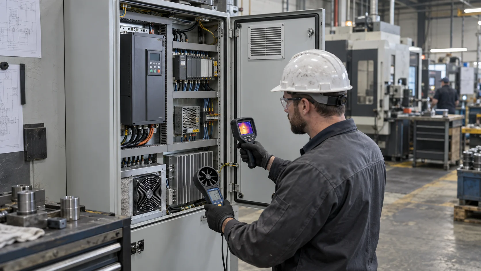
The release record should include heat-loss assumptions, air-density basis, airflow, pressure, fan voltage, PWM, RPM, current, filter condition, component temperature, acoustic observation, vibration, alarm delay and maintenance action. Capture a thermal image or temperature map of the populated cabinet so later wiring or drive changes can be compared against the same baseline.
How MEGA Tech Supports a Custom VFD-Cabinet Fan
We help panel builders and machine manufacturers turn drive losses and pressure data into a validated sample.
MEGA Tech develops custom DC axial fans, compact blowers and filtered fan assemblies for PLC cabinets, VFD panels, servo cabinets, machine tools, robotics cells and industrial power electronics. We review drive loss, cabinet temperature, filter and grille pressure, airflow direction, frame and cutout, voltage, PWM or analogue control, FG/RD feedback, noise, vibration, dust, humidity, altitude and service interval.
For a first review, send the drive model and loss data, machine duty cycle, ambient range, cabinet drawing or photographs, required airflow and pressure, filter data, available fan space, supply voltage, control and feedback, noise target and quantity. If you are replacing a Sanyo Denki, SUNON, Delta, NMB, ebm-papst or other established fan, include the part number and the measured installed condition. We can compare the performance envelope and provide samples for fit, pressure and thermal validation.
Our support includes parameter adjustment, P-Q testing, PWM/FG/RD customization, connector and wire changes, small-batch prototypes and production transition. We can help reduce the cost of an equivalent industrial cooling fan, but the replacement should be accepted only after the actual cabinet working point, reliability, environmental and alarm requirements are demonstrated.
Engineer FAQ: VFD and Control-Cabinet Cooling
Short answers for panel designers, machine builders and procurement teams.
Q: Can I size the fan from the VFD motor rating? A: No. Use the drive and cabinet losses that actually become heat inside the enclosure, then validate the installed pressure and temperature.
Q: Why does the fan run but the VFD still overheat? A: The filter may be loaded, the air may bypass the heat sink, the fan may be at the wrong working point, or a hot component may not receive the expected flow.
Q: Should the cabinet be pressurized? A: Filtered positive pressure can reduce uncontrolled dust ingress, but the fan, filter, outlets, seals and service procedure must be designed together.
Q: Is a high free-air CFM fan automatically better? A: No. Compare airflow at the installed pressure. A high-static-pressure fan or blower may deliver more useful flow through the final filter and duct.
Q: What fan does MEGA Tech recommend? A: For open filtered cabinets, start with a high-static-pressure axial fan; for restrictive ducts, evaluate a compact blower; for monitored panels, use PWM with FG/RD when the controller supports it. The final model requires heat, pressure, voltage and envelope data.
Q: Can you supply a small batch for a machine prototype? A: Yes. We can adjust the fan and sample quantity for prototype testing before production release.
Control-Cabinet Fan Design-Review Checklist
Use these questions before releasing a VFD or servo cabinet fan.
- Are drive, servo, power-supply and braking losses separated from motor output power?
- Which component defines the limiting temperature and derating threshold?
- Has the airflow path been mapped from filter to outlet, including cables and baffles?
- What are clean and service-limit filter pressures at the required airflow?
- Does the fan maintain the working point at high ambient, altitude and minimum voltage?
- Are PWM, FG/RD, startup, brownout and alarm recovery tested near switching equipment?
- What happens if the fan stops, the tach signal is lost or the filter alarm is ignored?
- Can the fan and filter be serviced without disturbing wiring, seals or machine safety?
- Has the populated cabinet passed the real acceleration, braking and warm-soak sequence?
- Has the replacement fan been judged by installed performance rather than frame size and free-air CFM?
