The converter that nobody hears until it stops
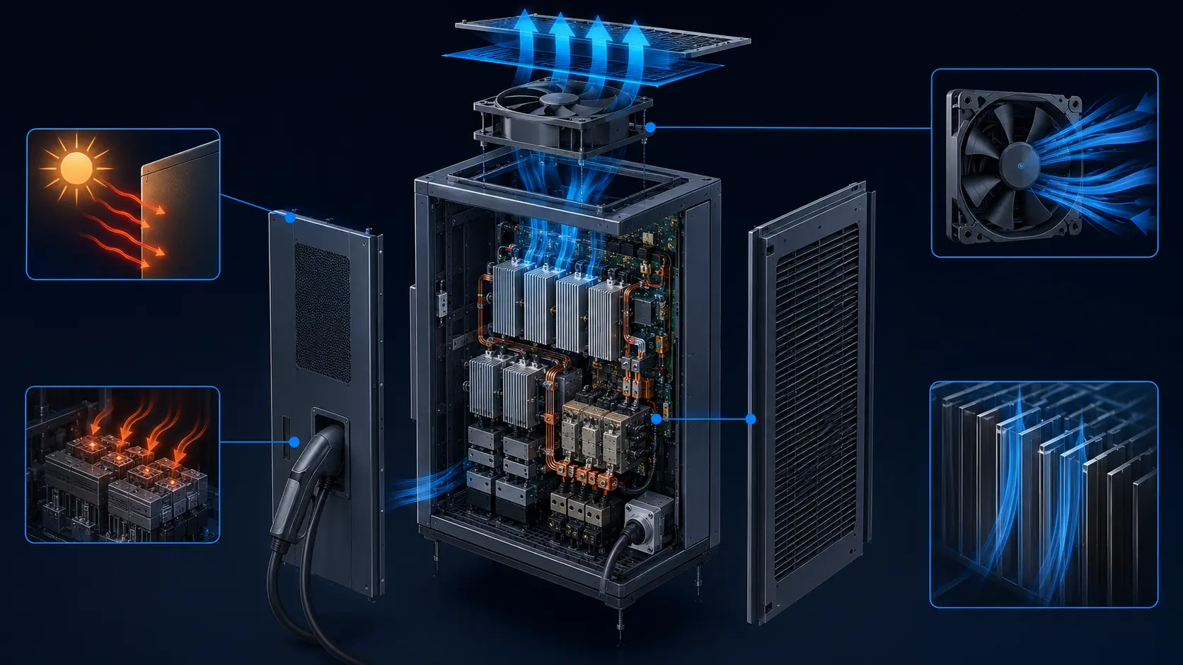
An 11 kW on-board charger and a 3 kW DC-DC converter share one enclosure, one heatsink and usually one fan. Their heat is not the hard part; everything else in a road vehicle is.
Charge infrastructure gets the attention because it is big and loud. The converters inside the vehicle are quieter, smaller and harder to cool: they sit next to a traction inverter, above a road surface radiating heat, and they run for hours in a garaged hot-soak condition after the vehicle has stopped. When they fail, the symptom is mundane - charging stops, derates, or refuses to start at a hot roadside charger - and nobody connects it to a fan.
Three conditions separate this duty from a cabinet fan. The inlet air is already hot, so the temperature rise available is small and the air itself is less dense. The enclosure is bolted to something that shakes for thousands of hours, which makes mechanical fatigue at least as important as thermal margin. And the surrounding angles include high-pressure wash-down and winter road salt, which decide whether a vent can exist at all.
This article works through the duty in that order: the loss budget, the temperature classification, the density argument that catches most designs out, the conduction path, the air path in a moving vehicle, vibration, sealing, cold and condensation, electrical control, noise, and finally the evidence a fan supplier should be asked for.
What makes the heat
Before arguing about airflow, count the watts. On this duty the number is smaller than engineers expect, and that is exactly why air cooling can work - if everything else cooperates.
A modern 11 kW on-board charger runs around 94-96 percent efficient, which puts its continuous loss near 440-660 W; take roughly 480 W at a typical operating point. A 3 kW high-voltage-to-low-voltage DC-DC converter at 95-97 percent adds roughly 90-150 W. Together that is about 600 W of continuous heat spread across a power stage, magnetics and a DC-link capacitor set, inside an enclosure of a few litres.
The peak is not the interesting part. What matters is duration: a domestic charge session is several hours, a fleet depot session may be longer, and both can start with the vehicle already heat-soaked from driving. The cooling system therefore has to hold its temperature limits through a long, flat plateau rather than through a short spike, which makes steady-state conduction and flow more important than transient capacity.
That is also why the enclosure usually has air cooling rather than a liquid branch from the battery loop. Six hundred watts is genuinely borderline: it is within reach of forced air at low-to-moderate ambient, and it becomes unreachable when inlet air, hold-down space and vibration together take away the margin. Knowing which side of that line a design is on starts with the classification of the air itself.
| Source | Rating | Efficiency | Continuous loss |
|---|---|---|---|
| On-board charger (AC to HV battery) | 11 kW | 94-96 % | About 440-660 W, commonly ~480 W |
| DC-DC converter (HV to 12 V / 48 V) | 3 kW | 95-97 % | About 90-150 W, commonly ~120 W |
| Combined into one cooling path | - | - | About 600 W sustained for hours |
Under-bonnet temperature is a classification, not a guess
Vehicle programmes do not negotiate ambient temperature verbally. They cite an ISO 16750-4 code, and that code decides every downstream number.
ISO 16750-4 defines operating temperature ranges by letter code, and the relevant part of the table for power electronics reads: F is -40 to 80 C, G is -40 to 85 C, H is -40 to 90 C, I is -40 to 95 C, J is -40 to 100 C and K is -40 to 105 C. Which code applies is set by mounting location and by the vehicle manufacturer's own requirement; under-bonnet and powertrain-mounted electronics commonly land in G to K.
The second clause is the one that bites. Where hot-soak applies, the standard adds 15 K to the maximum operating temperature. A unit rated code G sees 85 C in service and is expected to survive 100 C after shutdown with no airflow through the enclosure and no heat being generated to keep air moving. Any fan selected against the no-hot-soak number will look adequate on paper and wrong in the field.
Ask one question in every early review: which code is specified, and is hot-soak included? The answer determines inlet density, allowable rise, bearing temperature and therefore fan life - and it is far cheaper to fix at specification stage than after the enclosure is tooled.
| Code | Minimum operating temperature | Maximum operating temperature | Typical use |
|---|---|---|---|
| F | -40 C | 80 C | Warm locations away from the powertrain |
| G | -40 C | 85 C | Power-electronics enclosures - a common baseline |
| H | -40 C | 90 C | Hotter under-bonnet positions |
| I | -40 C | 95 C | Near exhaust or tightly packed bays |
| J | -40 C | 100 C | Severe locations, often with a hot-soak clause |
| K | -40 C | 105 C | Severe powertrain-mounted equipment |
Density: why 85 C air is a different fan duty
A fan moves volume. Heat removal depends on mass. At 85 C those two numbers diverge by more than twenty percent.
The required air mass flow is fixed by the duty, not by the fan: m = P / (cp x dT). For 600 W with cp about 1005 J/(kg x K) and an allowed rise of 15 K, the requirement is about 0.04 kg/s, or roughly 143 kg/h. That line is flat everywhere - it does not care what temperature the inlet air is.
What a given fan delivers does care. Take one fan moving a delivered 150 m3/h in the installed system. Mass flow is volume times density, and density falls with temperature: about 181 kg/h at 20 C inlet, 166 at 45 C, 157 at 65 C, 147 at 85 C and 139 at 105 C. Plot both numbers and they cross near 92 C: above that inlet temperature this fan can no longer hold a 15 K rise on 600 W at any speed that keeps the same delivered volume.
The practical consequence is that specifying flow in cubic metres per hour without stating the reference density is meaningless for this duty. State required mass flow, or state volume flow together with the inlet density it was calculated at, and check the design at hot-soak rather than at the nominal classification. If the fan cannot be made to fit, the honest alternatives are a larger flow or a smaller allowed rise - which usually means the heatsink needs more area, not a faster motor.

Where the fan cannot help
Six hundred watts crosses several resistances on its way out. Only two of them are the fan's responsibility, and knowing which is which saves most of the budget.
A representative ladder for this duty at 85 C inlet reads: semiconductor junction about 150 C, module base plate near 125 C, heatsink fins near 105 C, exhaust air about 100 C, inlet air at the grille 85 C. Each step is a thermal resistance in series, and the junction lands wherever the sum puts it.
The fan touches only the last one or two - fin-to-air convection and the enclosure's ability to bring fresh air to those fins. Interface material, mounting pressure and fin geometry belong to the module's mechanical design, and a faster fan on top of a poor interface buys noise rather than margin. Fix the interface, then buy airflow.
Orientation matters more here than in a fixed installation. The same enclosure sits at different angles in different vehicles, may see a hot surface radiating upward into it, and cannot assume a clean vertical chimney. Natural convection contribution is therefore unreliable and should be treated as zero for any safety-critical limit.

The air path in a vehicle that does not stand still
Vehicle installation removes the things a cabinet designer takes for granted: a fixed orientation, a clean plenum, and a predictable relationship between inlet and outlet.
Short-circuiting is the first failure. Exhaust air leaving the enclosure at 100 C is immediately available to the intake in a packed bay; unless there is a defined intake path and physical separation, part of the flow simply recirculates and the effective inlet temperature rises above the specified 85 C. Bay-scale CFD done early is cheaper than adding flow later, and the intake position should be chosen against the measured worst case, not against what looks tidy.
Second, the vehicle is moving. At speed there is ram air and an under-bonnet pressure field that can either help the fan or fight it; parked in a hot-soak condition, there is no forced flow at all and buoyancy may oppose the intended direction. Fan duty therefore has to hold at zero-vehicle-speed conditions, which are usually the charging conditions that matter most.
Third, everything nearby is a source: a radiator fan, a compressor, a neighbouring inverter. Shared intake spaces mean competing pressure sources, and a fan operating near stall on someone else's pressure field will deliver neither its curve nor its life. Physical separation, ducting to a defined source, and a check at worst-case adjacent operation belong in the design review.
Vibration: the failure mode nobody models
On mounted power electronics, fans fail from accumulated mechanical load at least as often as they fail from heat. Both act on the same bearing.
ISO 16750-3 defines the mechanical loads by mounting location, and the severity is not gentle: for commercial-vehicle cab-mounted equipment the random vibration test is run in accordance with IEC 60068-2-64 for 32 h per plane, with specified root-mean-square acceleration values of 21.3 m/s2 vertically, 11.8 m/s2 longitudinally and 13.1 m/s2 laterally. Vibration is broadband, so anything with a mechanical resonance inside that band is a fatigue problem rather than a strength problem.
A fan is a rotating assembly with its own resonances and a bearing whose load scales with the square of speed. Combine that with a bracket that has a mode near a strong content frequency and the bearing sees several times its design load for hundreds of hours. The usual sequence is not immediate failure: it is grease migration, rising noise, current drift, then seizure - which in a converter means derating or a charging stop, often attributed to 'the electronics'.
Four mitigations cover most of it. Select a bearing and lubrication for the temperature and vibration together, not for temperature alone. Keep the fan's own resonances and the bracket's first mode away from strong content in the input spectrum, and stiffen the mount rather than adding mass. Route the harness with strain relief so cable whip does not load the connector. And specify the fan's vibration qualification evidence explicitly, including the axis, duration and functional-status class it was tested to.
Water, salt and wash-down: choosing what gets to enter
Automotive sealing has its own code, and its own alphabet. Getting it wrong is either a flooded converter or an uncoolable converter.
Road vehicles use ISO 20653 rather than the generic IEC 60529 code, because vehicle equipment also has to survive high-pressure and high-temperature cleaning. The K suffix marks that difference: IP6K9K describes dust-tight equipment that also withstands close-range high-pressure hot-water jets, which is what a commercial vehicle wash or a winter road-cleaning jet actually delivers. A standard IP67 rating for immersion is not the same test and not automatically adequate for a wash-bay application.
Every opening has to be engineered against that requirement. Filtered intakes need a drain path and a media that does not hold water; louvers need geometry that throws water off before it reaches the fan; and any mesh fine enough for insects or grit adds pressure drop that has to be counted in the dirty condition. The hostile chemistry is not only water - winter road salt is conductive and corrosive, and it reaches places rain does not.
This is where the trade becomes explicit: better sealing means less free airflow, and sometimes the honest answer is a sealed enclosure with an internal circulation fan and conduction to the casing. That only works if casing area and external airflow are sufficient, which returns the problem to the loss budget and the interface resistances rather than to the fan.
Winter: cold start, condensation and the other extreme
The same converter that bakes in July starts at -40 C in February, and the condensation formed in between is what corrodes it.
Low-temperature behaviour is a mechanical and lubrication question before it is a thermal one. At -40 C, grease viscosity rises, start-up torque rises with it, and a fan that starts reliably at room temperature can stall at its lowest specified speed. Any control strategy that commands low speed must be validated at cold start, with rotation detection that reports zero when the rotor is not turning, rather than relying on a commanded value.
Condensation is the quieter hazard. An enclosure that has been warm and humid cools after shutdown, drawing in moisture-laden air; the coldest metal - usually the fin stack or the connector body - crosses the dew point first. Over a winter this produces corrosion and surface tracking rather than immediate failure, and it is the same physics that any sealed outdoor enclosure fights, only with a faster cycle count.
The countermeasure set is familiar: intermixing at low speed to keep cold surfaces slightly warmer than still air would, keeping the fan off during the highest-humidity window where that is better, ensuring there is a drain path and no trap, and verifying surface and insulation choices against cyclic damp-heat rather than against steady-state humidity alone.
Electrical reality: what the vehicle actually supplies
Desktop supply rails and vehicle rails have almost nothing in common. The fan has to survive the second one.
Vehicle electrical environments include cranking dips, load dump, jump-start conditions and reverse-polarity events, on either 12 V, 24 V or increasingly 48 V boards. A fan not rated for the whole range will either sit still when it is needed or be damaged by an event it never sees on a bench. Wide input range, reverse-polarity protection, soft start and behaviour during under-voltage all have to be specified, not assumed from the nominal supply.
Control method matters too. Voltage-based speed control is simple but loses authority at low supply voltage; PWM control holds command resolution across the range but injects switching content that interacts with onboard EMC and, in some designs, with the vehicle's own measurements. Speed feedback and rotation detection should be treated as diagnostic outputs to the vehicle controller, not optional extras, because they are the difference between a converter that derates gracefully and one that silently loses a fan.
Noise: the nearest neighbour hears the fan first
A home charger runs overnight. Whoever sleeps beside the garage becomes part of the acoustic requirement, whether or not it is written down.
Fan noise rises steeply with speed - it is the reason 'just increase the RPM' is never free. For a domestic charger the constraining case is normally quiet residential hours, which intersect exactly with the primary charging window. The engineering consequence is to buy noise margin through the heat path instead: more fin area, better interface, cleaner inlet and outlet geometry, and a control curve that reaches high speed rarely and briefly.
Tonal content matters as much as level. A blade-pass frequency that coincides with a bracket resonance produces a whine that is far more objectionable than broadband hiss at the same sound pressure. Because the enclosure is mounted to a structure that also carries road and tyre noise, the mount is part of the acoustic path, and isolators have to be chosen against the vibration loads they will see rather than against a noise target alone.
Life against a vehicle mission profile
Vehicles are judged over ten years and hundreds of thousands of kilometres. A fan datasheet quoted at 40 C does not describe that.
Bearing life falls steeply with temperature, and these two converters sit in the hottest enclosures in the vehicle. Combining that with broadband vibration means the honest life estimate has to come from testing to the actual duty - temperature, speed profile, and vibration input together - rather than from extrapolating a benign bench curve. Sequential testing (temperature then vibration) tends to understate the damage of combined exposure; combined exposure testing is slower and more expensive, and usually worth it for a part that is hard to reach in service.
Packaging decides whether the fan is serviceable at all. If the enclosure cannot be opened without de-energising the whole unit and draining anything, then a mid-life fan replacement becomes a workshop operation, and the life target has to be set accordingly. Where the fan is not realistically serviceable, design the life target to the vehicle rather than to the warranty period.
What can be asked for is cheap: measurement of the installed operating point, evidence of random-vibration qualification to the specified test method and duration, low-temperature start verification at the commanded minimum speed, and a documented failure mode for loss of rotation. Those four items turn a promising candidate into a specified part.
| Question | What to ask for | Why it matters |
|---|---|---|
| What does the installed operating point measure? | Airflow and pressure at the real inlet geometry and density | Volume output alone says nothing about the delivered air |
| How was vibration qualification done? | Test method, axis, duration, rms level, functional status | Combined heat and vibration is what the bearing actually sees |
| Does it start at -40 C at minimum command? | Cold-start test with rotation detection reported | A stalled rotor with a healthy-looking command is a silent failure |
| What does loss of rotation look like to the controller? | Feedback output behaviour and diagnostic flag | Turns a hidden failure into a managed derate |
What MEGA Tech can do here - and what we need from you
We build cooling fans for exactly this duty: specified around the vehicle environment, and validated on the customer's own enclosure before the BOM is frozen.
What we do is selection and customization around a real duty cycle. Frame size, thickness, voltage and operating range, speed curve, PWM control, FG/RD feedback, connector and cable length, bearing and lubrication selection, and protection against reverse polarity and startup conditions are all adjustable. Where an existing unit is being replaced - including machines built by Sanyo Denki (SAN ACE), SUNON, Delta, NMB or ebm-papst - we work from the measured installed duty rather than from the frame size alone, because equal outlines do not guarantee equal delivery on a given system curve.
What we need from you is the vehicle environment, not just a part number: converter ratings and efficiency or loss figures, the ISO 16750-4 temperature code and whether hot-soak applies, the ISO 16750-3 mechanical load class, the ISO 20653 sealing requirement, intake and exhaust geometry including filter and mesh, the electrical environment and control interface, the acoustic limit and its measurement condition, the target life and whether the unit is serviceable, and any measured system curve or thermal data from the existing build.
Where we stop is also part of the answer. We do not supply the converter power stage, the enclosure, the vehicle controller or the vehicle-level safety design: insulation coordination, creepage, functional safety and the vehicle qualification plan belong to the equipment manufacturer and its customer. Our scope is the air side of the thermal path and the evidence that it survives the duty.
- Fan selection against the installed system curve at worst-case inlet density and hot-soak temperature.
- Customization: frame, thickness, voltage range, speed curve, PWM, FG/RD, connector, cable, bearing and lubrication, reverse-polarity and soft-start behaviour.
- Vibration, temperature and combined-exposure qualification support against the specified ISO 16750-3 profile.
- Sample build, instrumented test on the real enclosure, and a documented operating point before production release.
Engineer FAQ: On-Board Charger and DC-DC Fan Selection
Short answers to the questions that come up once the enclosure is tooled and nobody wants to change it.
Q: Is a higher-RPM fan the fix for an enclosure that derates in summer? A: Only if the path can use the extra flow. At 85 C inlet the limiting factor is often delivered mass flow, and above the crossover a faster fan mostly buys noise and a worse operating point.
Q: Do we specify airflow in m3/h or kg/s? A: State mass flow, or state volume flow together with the density it was calculated at. Required mass flow is set by the watts and the allowed rise; delivered mass flow falls as inlet air gets hotter.
Q: How much does the 15 K hot-soak addition really change? A: It moves the design point by roughly one ISO 16750-4 code, into the region where a marginal fan can no longer hold the same rise - check the hot corner explicitly rather than the nominal one.
Q: Our fans pass thermal testing but fail in field returns. Why? A: Usually accumulated vibration. Look at the bracket's first mode, the bearing's temperature rating together with its vibration load, harness strain relief, and whether the fan's qualification covers 32 h per axis of broadband random input.
Q: Is IP67 enough for a vehicle installation? A: Not automatically. Vehicle equipment is rated under ISO 20653, and the K suffixed ratings cover high-pressure hot-water cleaning that an immersion rating does not test.
Q: Can we run the fan at low speed to avoid noise at night? A: Yes, but validate it: cold start at -40 C and rotation detection at minimum command are exactly where low-speed strategies fail quietly.
Q: What can MEGA Tech customize for this duty? A: Frame, thickness, voltage range, speed curve, PWM, FG/RD, connector, cable, bearing and lubrication, reverse-polarity protection and startup behaviour - selected against your measured duty and validated on your enclosure.
Questions for the On-Board Cooling Design Review
A short checklist that keeps a summer derate from turning into an endless fan swap.
- Which ISO 16750-4 temperature code applies, and is the hot-soak addition included?
- What is the combined loss in watts, and is it stated for continuous operation rather than peak?
- Is the airflow requirement stated as mass flow, or as volume flow with its reference density?
- Where is the crossover between required and delivered mass flow, and how much margin sits below it?
- Which threshold limits life first - power stage junction, capacitor, magnetics or the fan bearing?
- Which ISO 16750-3 mechanical load class applies, and which bracket and fan resonances sit inside that band?
- Which ISO 20653 rating is required, and does the inlet design drain and exclude water under wash-down?
- What does the fan do at -40 C start, at minimum commanded speed, and what does the controller see if it does not rotate?
- What is the acoustic limit and at what measurement condition - including residential overnight charging?
- Has the candidate fan been measured on the actual enclosure and qualified to the actual vibration profile, or only on a bench?