
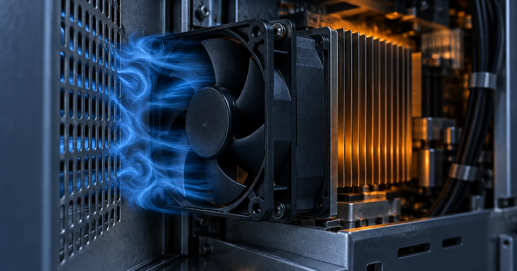
An installed fan is not the fan that was measured
A published noise figure describes one fan, at one speed, at one distance, in one room. The product you are shipping is none of those four things at the same time.
Start with the range that a single model number covers. The SANYO DENKI 9CRH0612P6G001 is a 60 mm counter-rotating fan. Its own specification table quotes 26,100 RPM and 78 dB(A) at a PWM duty cycle of 100 percent, and 3,900 RPM and 34 dB(A) at a duty cycle of 20 percent. That is a 44 dB spread on one part number. A specification written as 'fan noise 78 dB(A)' and a specification written as 'fan noise 34 dB(A)' can both be true of the same fan, and neither of them is a property of the installation.
The installed value then moves again for three reasons the data sheet does not model. The fan works against the impedance of the real chassis, so its operating point moves along the P-Q curve and its noise moves with it. The air approaching the inlet has to come around whatever structure sits in front of it, and a close, sharp obstruction changes both the broadband level and the tonal content. And the vibration the fan produces has a path into the panels and brackets it is fixed to, which can radiate more sound than the fan itself.
The practical consequence is that 'this fan is too loud' is not yet a diagnosis. The useful question is which of the three mechanisms is responsible, and that question is settled by a measurement rather than by reading another data sheet. This article sets out the four things worth recording: the operating point, the clearance in front of the inlet, the mounting condition, and the band spectrum.
What the published dBA figure actually is
A number without its measurement method is not yet a specification. Read the method before you read the value.
SANYO DENKI publishes fan noise as an average value measured 1 m from the air intake side of the fan, with the fan suspended on a special frame inside an anechoic chamber, in accordance with JIS B 8346. That one sentence fixes three things a reader would otherwise have to guess: the distance, which side of the fan, and what the fan was attached to while it was measured.
For air-moving equipment in general the usual route is different. ANSI/AMCA 300 is the reverberant room method for sound testing of fans. The fan runs in a qualified room and its sound pressure is compared band by band against a calibrated reference sound source, so the room's own acoustic signature can be subtracted. What that comparison produces is a sound power level, which is a property of the fan rather than of the room. ANSI/AMCA 301 then defines how a manufacturer may calculate ratings at other sizes and speeds from that laboratory data, so that ratings from different suppliers are generated the same way.
Two details in that scheme matter to anyone reading a rating. The certified quantity is the sound power level, and the certification tolerance is plus 6 dB in the first octave band and plus 3 dB in bands 2 to 8. Sound pressure levels are not certified at all. A rating is therefore a bounded statement about a fan in a laboratory configuration, not a prediction for your enclosure.
Sound power level and sound pressure level are not interchangeable, and the difference explains most arguments about fan noise. Sound power level says how much acoustic energy the fan radiates, and it does not change with distance or with the room. Sound pressure level is what a microphone at a point reads, and in a free field it falls by about 6 dB each time the distance doubles. Converting one into the other requires the distance, the directivity and an assumption about the room. A supplier quoting sound power and a customer measuring sound pressure are both correct and will not agree.
| Quantity | What it describes | What it does not tell you |
|---|---|---|
| Sound power level | The acoustic energy the fan radiates, in dB referenced to 1 pW | The level at any particular listener position |
| Sound pressure level | What a microphone at a stated point and distance reads | The total output of the fan, independent of the room |
| A-weighted level | The spectrum compressed into one number using the A-weighting curve | Whether a narrow tone is present |
| Octave or one-third-octave band level | Level per band from 63 Hz to 8 kHz | Whether a band contains a line or only broadband noise |
| Prominence ratio and tone-to-noise ratio | How far a discrete tone stands above the noise around it | The level of the rest of the spectrum |
One part number can span a wide noise range
Before comparing two fans, fix the operating point. Most of the apparent difference between candidates disappears once both are asked for the same airflow.
The counter-rotating fan pair is not an oddity of one product. The same manufacturer's 60 by 60 by 76 mm 9CRLB0612P0G001 is rated at 19,700 RPM and 75 dB(A) at full duty and at 5,300 RPM and 43 dB(A) at a duty cycle of 20 percent, a 32 dB spread on the same model number and the same data sheet.
The reason is the fan law set out in the next section. Sound power is roughly proportional to the fifth power of speed, so the acoustic level falls far faster than the airflow. Taking a fan from a 100 percent duty cycle to a 20 percent duty cycle removes about 80 percent of the speed, about 80 percent of the airflow and about 97 percent of the acoustic power.
This changes how an acoustic requirement has to be written. 'No more than 40 dB(A)' is not a requirement until the airflow, the static pressure and the control state at which it must be met are named. Once they are, two things become possible: the fan can be selected against the point it will really run at, and the control curve becomes part of the acoustic design instead of an implementation detail.
It also changes the answer to the usual question. If the fan only has to reach full rating on the hottest day of the year, or only during a fast charge, then the level the user hears for the rest of the time is the level at the normal duty point, which can be 30 dB lower. Recording the duty cycle profile next to the acoustic limit is often worth more than buying a quieter fan.
What a speed change does to the noise
The published fan laws give a usable first estimate for a speed change, and a useful warning about how much to trust it.
For a given fan at constant air density, the fan laws relate the three performance quantities to speed: volume flow varies with speed, static pressure with the square of speed, and shaft power with the cube. The acoustic version of the same set of laws is a 50 log10 relationship, so the change in sound level is about 50 times the logarithm of the speed ratio. Halving the speed gives roughly minus 15 dB; taking 20 percent off the speed gives roughly minus 5 dB. A fan of a different but geometrically similar size adds a further term, about 70 times the logarithm of the diameter ratio, which is the arithmetic behind the standard advice to move the same air with a larger fan at a lower speed.
Air density enters the acoustic law through its own 20 log10 term, and this is why altitude and hot air have to be treated separately. A fan in thinner air produces less static pressure and less acoustic power, but it also moves less mass flow, so the cooling task does not become easier just because the level falls.
Treat the logarithm as a screening tool, not as an acceptance criterion. The two examples from the previous section move from a 100 percent duty cycle to a 20 percent duty cycle, a speed ratio near 0.15. The 50 log10 rule predicts a 41 dB reduction for the counter-rotating fan, and the specification table shows 44 dB; it predicts 29 dB for the 9CRLB, and the table shows 32 dB. The estimate is close enough to choose between two control strategies and not close enough to sign off a limit against. Write the acceptance value against the measured ladder on the data sheet, or against your own measurement.
| Change applied | Predicted sound level change | Effect on airflow and static pressure |
|---|---|---|
| Speed reduced 20 percent | About minus 5 dB | Flow minus 20 percent, static pressure minus 36 percent |
| Speed reduced 50 percent | About minus 15 dB | Flow minus 50 percent, static pressure minus 75 percent |
| Speed increased 20 percent | About plus 4 dB | Flow plus 20 percent, static pressure plus 44 percent |
| Air density halved by altitude | About minus 6 dB | Same volume flow, about half the mass flow |
| Frame diameter doubled at the same speed | About plus 21 dB | Flow up by about eight times at the same speed |
Blade pass frequency: the tone a single number hides
A fan produces broadband noise and tonal noise at the same time. The tonal part is predictable, and it is the part a single dB figure cannot show.
Broadband noise comes from turbulence: vortex shedding at the blade trailing edges and tips, and the general mixing of the discharge jet. Tonal noise comes from the periodic repetition of the same geometry past the same point. For a fan with Z blades turning at N revolutions per minute, the blade pass frequency is Z times N divided by 60. ANSI/AMCA 301 gives the same expression inside its sound rating method, which is a useful signal that the tone is treated as a design quantity rather than as an artefact.
Two examples show why the frequency matters as much as the level. A seven-blade fan at 3,000 RPM gives seven times 50, or 350 Hz. A five-blade fan at 12,000 RPM gives five times 200, or 1,000 Hz. The first sits where the ear is relatively insensitive and where A-weighting removes a large part of the level; the second sits at 1 kHz, where the ear is most sensitive and where A-weighting adds nothing. Two fans with the same dBA figure can therefore sound completely different, and the one with the higher overall figure can be the more acceptable product.
This is why the standards do not rely on the overall level. ECMA-74, which is the industry noise test code for information technology and telecommunications equipment and is published as ISO 7779, specifies a method for deciding whether the noise emission contains a prominent discrete tone. The tone-to-noise ratio compares the energy of the peak against the noise energy in the critical band centred on it, and a tone counts as prominent when that ratio exceeds 8 dB at 1,000 Hz and above, or a larger margin at lower frequencies. The prominence ratio takes a different route and calls a tone prominent when the critical band around it sits 9 dB or more above the average of its neighbouring bands. The successor document, ECMA-418-1, carries the current criteria and the critical band expressions.
The engineering consequence is a two-part acceptance criterion. The broadband limit controls general annoyance and the exposure question. The tone criterion controls the whistle, the hum and the complaint that arrives after the product has shipped. A product can pass with a comfortable margin on the overall figure and still fail on one line, which is why a limit written only in dBA does not protect the design.
The blade pass frequency is not the only line in the spectrum. Its harmonics appear at integer multiples, and modulation from an uneven inflow or from a second fan running at a slightly different speed produces sidebands around it, spaced at the difference frequency. Two nominally identical fans at slightly different speeds produce a slow beating tone that can be more objectionable than either fan measured alone.
Where the installed noise comes from
Four mechanisms account for most of the gap between the catalogue figure and what the user hears. Only one of them is about the fan.
The approach flow is the first mechanism. A fan needs a clear and reasonably uniform inflow. When the inlet sits close to a wall, a printed circuit board, a cable bundle or a filter frame, the air has to turn sharply to enter, and the velocity profile across the inlet stops being uniform. The result is unsteady blade loading, which shows up as both a higher broadband level and a stronger tone at the blade pass frequency.
SANYO DENKI gives a simple rule for the axial clearance in front of the fan: the distance should exceed the difference between the blade outer diameter and the motor boss diameter. For a 60 mm square fan that is 58 mm minus 23 mm, or 35 mm, and the company recommends about 40 mm or more in practice.
Sharp edges are the second mechanism. A square-edged aperture, a punched grille or a card guide placed close to the inlet face sheds vortices straight into the impeller. The classic observation from fan manufacturers is that the same obstruction costs much more on the inlet side than on the discharge side, because the inlet flow is still accelerating and is therefore far less tolerant of disturbance, while the discharge flow has already been energised. That asymmetry is why a design that behaves with the obstacle downstream can develop a loud tone when the same obstacle is moved upstream during a mechanical revision.
The structure is the third mechanism. The fan applies a force at the shaft rotational frequency, at the blade pass frequency and at their harmonics, and it transmits that force into whatever it is bolted to. A flat panel has its own natural frequencies, and when one of them sits close to an excitation frequency the panel radiates far more sound than the fan does. Thin enclosure skins, large unsupported covers and long cable trays are the usual offenders.
Recirculation is the fourth mechanism, and it is usually the consequence of the other three. Air that leaves the fan and returns immediately to the inlet carries heat back with it, raises the inlet temperature and adds its own noise. In service this appears as an inlet air temperature higher than the ambient the design was written against, together with a noise level that does not fall as much as the fan law predicts when the speed is reduced.

When a panel or a bracket answers the fan
Structural resonance is not a special case. It is the normal behaviour of any thin panel with a fan bolted to it.
The design question is whether any panel, bracket or cover has a natural frequency close to the shaft frequency, the blade pass frequency or one of their harmonics. If it does, the panel becomes a second radiator, and the acoustic result can be dominated by a surface that was never intended to make sound.
A resonance can be moved in two directions. Adding stiffness raises the natural frequency; adding mass lowers it. The direction that helps depends on whether the excitation is above or below the resonance. What matters more is the separation: an isolator only works when its own natural frequency is well below the frequency it is being asked to reject, and the conventional design target is a factor of two to three, not ten percent.
A published study of a cooling module in a vehicle shows the practical size of the effect. After the dynamic stiffness of the isolation pads was reduced so that the module's natural frequency moved from about 40 Hz to about 32.5 Hz, the noise peak at the original frequency fell by about 19 dB, and the total sound pressure level fell by about 3.3 dB. The ratio between the excitation frequency and the isolator natural frequency is the transferable lesson, not the specific frequency.
The same principle explains why a compliant mount can do nothing useful. Metal-to-metal contact through a screw, a cable gland or a rigid bracket short-circuits the isolator completely. That is why the mounting detail, not the mounting material, is usually the deciding factor in a production build.
Above a certain frequency a panel starts to radiate airborne sound more efficiently, and damping treatments become more useful than stiffening. In a compact product the practical sequence is to stiffen or damp the panel, then break the transmission path, then isolate the fan, and only then consider changing the fan itself.
PWM and the motor drive: electrical noise you can hear
The switching frequency is normally chosen to be inaudible. Everything around it is not automatically safe.
Four-wire fans take a constant supply voltage and a separate PWM input, and the fan's own driver converts the duty cycle into a speed command. The switching frequency of that drive is normally specified well above the audible band: SANYO DENKI quotes a PWM input frequency of 25 kHz in the notes to its specification tables, which is above the upper limit of human hearing and is the reason the carrier itself is not audible.
The carrier is not the risk. The risk is what sits around it. If the drive frequency drifts into the audible range, or if the motor's mechanical or magnetic response produces a component at the switching frequency or at one of its sidebands, the result is a high-pitched whine that changes with duty cycle. Supply ripple can do the same. The published operating precaution is explicit: use a supply with ripple below 5 percent, with low line noise and low surge, because the fan contains an electronic circuit.
There is a second and more common effect. Most fans are not intended to run at very low duty cycles. SANYO DENKI notes that below about 20 percent duty, on the models illustrated in its technical material, the speed is unstable. An unstable speed produces a wandering tone and an airflow that is hard to validate. If the acoustic requirement has to hold at stand-by conditions, confirm the minimum stable duty and set the control curve above it rather than assuming the fan will be quiet simply because the command is low.
Bearing noise is the other source worth separating from the drive. It is mechanical, it grows with speed, and it is the reason a fan's noise figure rises over life as the grease in the bearing is depleted. The published life definition for these fans is the point at which speed has fallen to 70 percent of its initial value, quoted at L10, which is a reminder that the acoustic specification and the life specification both describe the same bearing.
One consequence for validation: ask for the fan to be characterised with the control interface and the supply that will actually be used. A fan measured at 100 percent duty on a laboratory supply is not characterised for a 30 percent duty signal from a controller with different rise times and a different pull-up.
Measure at the operator position, at the real operating point
A noise result is only comparable when the distance, the position, the operating point and the room are all stated.
ECMA-74 and ISO 7779 define where to measure. Where the equipment has an operator position, the measurement for tone prominence is made there. Where it does not, it is made at the bystander position with the highest A-weighted level, and at every other position within 0.5 dB of it. The reason to keep that structure is simple: the tone the customer complains about is measured where the customer sits, and that is rarely one metre from the intake.
The operating point has to be the worst case, and the worst case is not always full speed. A fan at full speed in a cool room is mostly broadband. A fan at 40 percent duty in a warm room may be working against a higher system resistance and sitting on a panel resonance, and that is the condition that generates the complaint. Record the level at every control state the product will actually use, including the start of a heat-up transient.
Background noise has to be separated from the fan. In a free field, halving the distance adds about 6 dB, so a measurement taken at 30 cm cannot be compared with a catalogue figure taken at a metre. Where the measured level sits within a few dB of the background, correct it or abandon it rather than reporting a number that is mostly the room.
Then record the spectrum. A one-third-octave spectrum with the blade pass frequency marked on it turns an argument into a finding: it shows whether the level comes from broadband turbulence or from a single line, and it shows whether that line moves with speed. A line that moves with speed is aerodynamic; a line that does not is structure or electronics.
| What to record | Why it matters | Minimum detail |
|---|---|---|
| Operating point | Sound moves with airflow and pressure | Airflow, static pressure and RPM together |
| Control state | The worst case is not always full speed | PWM duty cycle or voltage, and the control curve |
| Measurement position | Distance and side change the number | Distance, height, side of the fan, room type |
| Level type | Sound power and sound pressure are different quantities | Which quantity, and the weighting applied |
| Spectrum | A single line disappears inside one number | One-third-octave bands with the blade pass frequency marked |
| Mounting condition | Panels and brackets carry vibration | The bracket, gasket or grommet that will ship |
| Background | A room can set the reading | Background level at the same position |
Engineer FAQ: fan noise in real equipment
The acoustic target has to be written alongside the thermal and electrical operating conditions, not after them.
Q: Why is my installed fan louder than its datasheet figure? A: The device can have a different pressure point, inlet distortion, a guard or a card guide in front of the inlet, a different mounting path, a panel resonance or simply a different measurement method and distance from the catalogue test.
Q: Is the fan with the lower dBA always the better choice? A: No. Confirm that it still meets the required airflow and static pressure at the real operating point, and compare its band spectrum rather than its single figure. A quiet fan that under-cools the product is not a successful selection.
Q: When do I need a spectrum instead of an overall level? A: Whenever people report a whistle, a hum or a tone, and whenever the product has a strict acoustic limit. A one-third-octave spectrum reveals a blade pass tone or a structural resonance that the overall figure hides.
Q: Can PWM make a fan quieter? A: It can remove a large part of the noise by removing unnecessary speed, and the fan law says the saving is steep. But the switching frequency, the supply ripple, the minimum stable duty and the blade pass tone all have to be checked in the complete product.
Q: How far should the obstruction in front of the inlet be? A: The rule quoted by SANYO DENKI is a clearance greater than the blade outer diameter minus the motor boss diameter, which for a 60 mm fan means about 40 mm. Measure the installed noise if that clearance is not available, because a close, sharp edge adds a tone rather than only a few decibels.
Q: What should a custom sample prove? A: Airflow, static pressure, temperature rise, current, RPM, PWM response, the one-third-octave sound spectrum at the mounting that will ship, and the vibration measured on the panel the fan is fixed to, all at the worst-case thermal load.
Questions for a Design Review
Take these seven questions to the review that approves the acoustic requirement, not to the review that approves the drawing.
- At which airflow, static pressure and control state must the acoustic limit be met, and is that condition recorded in the specification?
- What is the clearance in front of each fan inlet and each outlet, and is any printed circuit board, cable bundle, grille or filter frame inside it?
- What is the blade count and the full duty speed, and which frequency does the blade pass tone land on? Is any panel, bracket or cover natural frequency within 20 percent of it or of a harmonic?
- Which surface radiates the noise the user hears, and has the transmission path been checked for metal-to-metal contact that bypasses the isolator?
- Where will the level be measured, at which distance and on which side, and what acceptance method decides that a tone is prominent?
- What is the minimum stable PWM duty cycle for the selected fan, and does the control curve stay above it in every operating mode including stand-by?
- Has the level been measured with the supply and the controller that will ship, at the worst-case thermal load, and has the background been recorded at the same position?
From an acoustic target to a validated fan sample
MEGA Tech can develop a DC or EC fan around the frame, thickness, airflow, static pressure, speed, PWM command and FG or RD output, connector, cable, bearing and environmental requirements of your product. The selection is made from a stated duty point rather than from a part number, and the sample is validated in the customer's own assembly so that the acoustic result is measured where it will actually be heard.
For a noise-limited design the useful first reply from us contains the fan-side operating point the design implies, the blade pass frequency of the candidate, the PWM duty cycle range we can hold stable, and the measurements still missing before an acoustic limit can be signed off. That is what turns a noise complaint into a specification.
Three boundaries are worth stating plainly. We do not supply the enclosure, the panel stiffening, the acoustic lining or the vibration isolation hardware, although we will tell you what the fan side needs. We do not accept a replacement on the basis that two fans have the same outline dimensions or the same dBA figure. And we cannot make a fan quiet enough to compensate for an inlet that has been blocked by a card guide or a cable loom placed in front of it. The comparison we can support is a measured one: same fixture, same operating point, same control command, same acceptance limits.
- Custom DC and EC fans in axial and centrifugal formats
- Selection from the installed duty point rather than from a catalogue figure
- One-third-octave spectrum and vibration measured on a production-representative sample
- Sample validation in the customer's own assembly and fixture
