
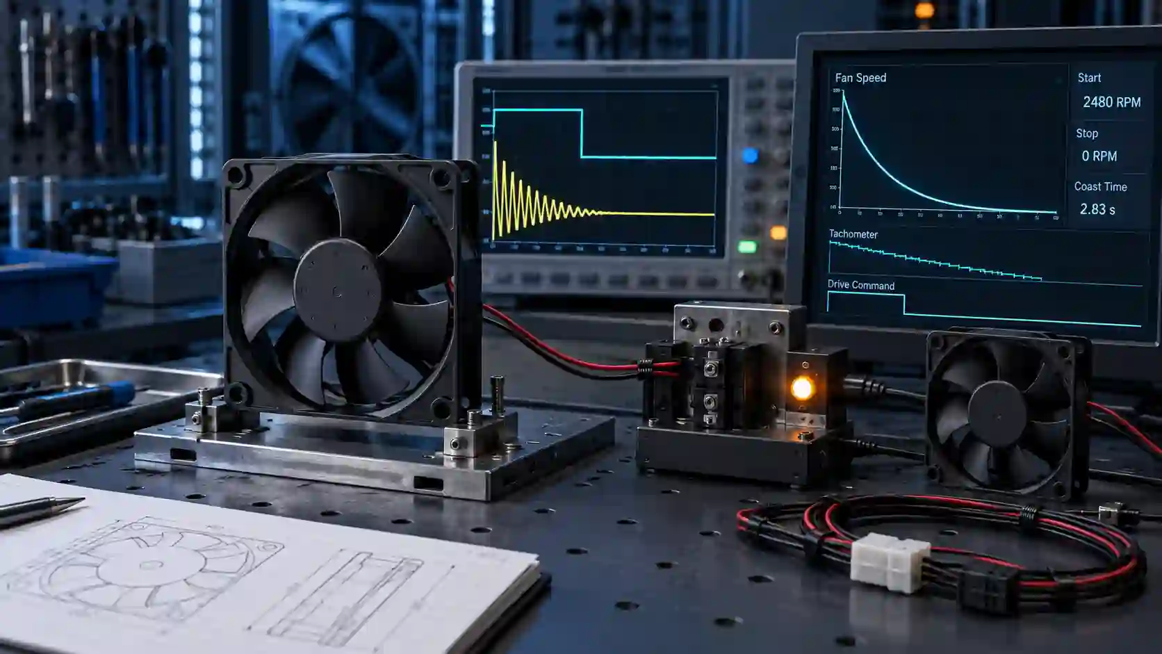
A fan can meet the airflow target and still fail the control requirement
Cooling-fan integration is not only about how much air moves while the product is running. The controller also has to know how to start, regulate, detect and stop the fan.
A two-wire fan looks simple: apply power and it runs; remove power and it stops. In a real product, the rotor has inertia, the BLDC electronics have their own behavior, and the product may have a timing requirement after power-off. A fan can therefore pass its normal airflow test and still be unsuitable for a service door, moving mechanism, optical path or safety-related sequence.
The same integration issue appears when a premium fan is replaced. A candidate may match the frame, voltage and free-air airflow while using a different startup threshold, tachometer behavior, PWM response, restart delay or coast-down time. Those are not secondary details when the product controller depends on them.
This article explains the control questions to define before selecting a fan, then uses an anonymised MEGA Tech project in which a two-wire fan's reported coast-down time was reduced from approximately 15–18 seconds to approximately 7 seconds without adding a signal wire. The result is project-specific, but the validation method is broadly useful.
First define what stop means
A statement such as ‘the fan must stop quickly’ is not yet an engineering acceptance criterion.
There are at least three different requirements hiding behind a fast-stop request. The product may need the rotor below a residual RPM threshold, it may need airflow to fall below a process limit, or it may need a complete mechanical stop before an operator can access a nearby part. Those are different measurements and may require different fan or system solutions.
Write the requirement as a timed sequence: starting voltage and stabilized speed, power-off trigger, measurement point, residual-speed or airflow threshold, maximum allowed time, repeat count and ambient condition. If the fan is near a moving assembly, also define the guard, interlock and isolation requirements separately. A fan brake can support a machine safety design, but it is not a replacement for risk assessment, guarding or energy isolation.
The same discipline applies to startup. Define the maximum allowed startup time, the lowest supply voltage, the coldest ambient condition and whether the controller expects a tachometer pulse before enabling the next stage. A candidate that stops faster but fails to start reliably is not a successful replacement.
| Question | Example definition | Why it matters |
|---|---|---|
| Starting state | Rated voltage, stabilized speed, ambient and mounting | Coast-down time depends on the initial mechanical and electrical state |
| Stop threshold | Below a defined RPM, airflow or full-stop condition | A residual-speed target is not the same as a complete stop |
| Timing trigger | Supply removal at a defined controller or relay event | Contact bounce and delayed measurement can change the result |
| Restart | Restart after stop at low and rated voltage | Braking energy and control changes must not damage startup behavior |
| Safety boundary | Guard, interlock and isolation remain system functions | Fan braking is not a machine emergency-stop substitute |
Two-wire, three-wire and four-wire fans do not offer the same control surface
A two-wire fan carries supply and return. The product can switch power or vary the supply, but it does not automatically have a dedicated command or feedback line. That makes the fan simple to wire, but it also makes speed control, fault detection and controlled stopping more dependent on the fan's internal electronics and the host power stage.
A three-wire fan commonly adds a rotation or tachometer output. The controller can observe speed, but the control command may still be through supply voltage or another system-side method. A four-wire PWM fan separates the fan supply from the logic command and usually provides a tachometer output, but the exact PWM frequency, polarity, logic levels, pulse-per-revolution value, minimum duty and startup behavior still belong to the selected fan specification.
Intel's 4-wire reference requirements use a nominal 25 kHz PWM signal, specify a tachometer output and define startup current and fan-supply limits for that reference interface. Those numbers are useful when designing against that interface; they are not permission to assume every industrial fan implements the same response. Confirm the exact fan and controller together.
For a replacement review, add the control interface to the same checklist as frame size and P-Q curve. A fan that cannot report the expected signal, or that interprets 0% duty differently, can create a thermal or diagnostic failure even if the air performance is acceptable.
- Two-wire: power interface only; startup, stopping and speed behavior depend heavily on the internal driver and supply stage.
- Three-wire: adds speed or rotation feedback, but the command method must still be defined.
- Four-wire: separate supply and PWM command plus commonly available tachometer feedback.
- Verify logic levels, PWM frequency, polarity, pulse count, minimum duty and restart behavior from the exact fan specification.
- Do not treat a matching connector as proof of signal compatibility.
What happens inside a BLDC fan after power is removed
Removing the supply does not make a spinning rotor mechanically disappear. The rotor continues because of inertia. Depending on the motor and driver topology, the spinning motor can also generate back-EMF while it decelerates. The fan's internal circuit, mechanical friction, air load and any braking path determine how quickly the speed falls.
A controlled brake must manage the energy and voltage created during deceleration. The correct implementation depends on the motor winding, driver, supply, protection parts, allowable temperature rise and the customer's power input. A circuit copied from another motor is not a universal fan solution.
That is why a custom braking request should be treated as a fan-platform change with normal operation, low-voltage behavior, restart, repeated cycles, noise, vibration, electrical transients and thermal loading in the acceptance plan. The design goal is not merely a shorter time on a stopwatch; it is a shorter, repeatable stop without damaging the fan or disturbing the product power system.
An anonymised MEGA Tech case: 15–18 seconds down to approximately 7
The customer had a fixed wiring constraint, so the solution had to work inside the two-wire fan rather than adding a control lead.
An anonymised customer needed the fan to stop more quickly after power-off. The existing two-wire fan continued to coast for approximately 15–18 seconds, which did not fit the product's service and moving-equipment sequence. The fan footprint also had to remain unchanged.
MEGA Tech reviewed the power-off behavior and developed a braking approach within the fan electronics. No additional PWM, tachometer or brake wire was added. The sample was checked not only for coast-down time, but also for normal run performance, startup, restart and electrical compatibility with the customer's supply interface.
The reported result was approximately 7 seconds to the defined stopping condition. That is a reduction of roughly 8–11 seconds, or about 44–61% compared with the original reported range. This percentage is a calculation from the project's reported values, not a universal product claim; a new fan and application require their own acceptance threshold and repeat test.
- Interface: two-wire supply retained.
- Mechanical constraint: fan footprint retained.
- Design response: braking behavior developed inside the fan electronics.
- Validation: normal run, startup, restart, power-off and electrical compatibility checked together.
- Result boundary: project-specific and tied to the defined stopping condition.
The validation plan: measure the whole sequence, not one stopwatch number
Start with the fan at a defined stabilized speed and record the voltage at the fan connector. Remove power using the same relay, MOSFET or controller event used by the product. Capture the supply waveform, any back-feed or transient, tachometer or optical speed signal, current and the time to the agreed threshold.
Repeat the test at rated voltage, operating-voltage limits and representative temperatures. Include cold start, repeated stop-start cycles and restart after an interrupted stop. If the fan sits near a grille, duct or moving assembly, keep the product mounting and air path in the fixture; aerodynamic load changes the deceleration behavior.
Finally, check what the product sees: controller fault flags, sensor plausibility, acoustic impulse, vibration, nearby electronics and temperature of the fan driver. A fast stop that creates a voltage transient or causes a controller reset is not a finished solution.
| Test block | Record | Acceptance question |
|---|---|---|
| Run state | Voltage at fan, RPM, current, temperature and mounting | Was the starting condition repeatable? |
| Power removal | Trigger waveform, supply fall time and fan-side voltage | Did the product remove power in the intended way? |
| Stopping | RPM or optical trace, time to defined threshold, noise and vibration | Does the fan meet the time requirement without a new failure mode? |
| Electrical effect | Back-feed, transient, current and driver temperature | Does braking remain inside fan and system electrical limits? |
| Restart / cycling | Cold start, low voltage and repeated stop-start cycles | Does the fan restart reliably after the custom stop behavior? |
- Define the threshold: residual RPM, airflow limit or complete stop.
- Use the same starting speed and power-off trigger for reference and sample.
- Test rated voltage, voltage limits and representative temperatures.
- Check back-feed, transients, noise, vibration and electronics temperature.
- Repeat enough cycles to expose intermittent restart or control faults.
When custom control behavior is worth specifying
Customization is justified when the product constraint is real, repeatable and difficult to solve with a standard fan.
A standard fan may be sufficient when the product only needs continuous airflow and has a tolerant power interface. A custom configuration becomes valuable when the product has an existing two-wire harness, strict power-off timing, limited controller I/O, a special restart sequence, a required FG/RD behavior or a replacement target with a different control response.
MEGA Tech can review the air requirement and the control requirement together: frame and thickness, voltage range, P-Q curve, PWM response, FG/RD output, connector, cable, startup, coast-down, bearing, environmental protection and mounting. The sample should then be validated in the representative enclosure or fixture before the configuration is frozen for production.
This approach protects both sides of the design. The customer does not need to redesign its harness just to obtain the required behavior, and the fan supplier does not have to describe an unverified electrical behavior as a universal specification.
- Keep the current footprint and wiring when the product cannot change.
- Define what the controller must command and what it must observe.
- Customize the fan electronics only with the complete voltage and load conditions known.
- Validate airflow, pressure, startup, stopping, restart and fault response together.
- Freeze the control behavior and acceptance method for repeatable production.
Engineer FAQ: Two-Wire Fan Braking and Power-Off Control
Use these questions to separate a fan's stop behavior from the product's safety and control responsibilities.
Q: Does removing power guarantee an immediate stop? A: No. The rotor can continue to coast because of inertia, air load and internal driver behavior. Define the stopping threshold and measure the time from a repeatable starting condition.
Q: Can an external power switch add braking to any two-wire fan? A: No. Braking depends on the fan motor, internal electronics, switching stage, energy path and voltage limits. A circuit suitable for one fan platform may damage another or create a supply transient.
Q: Is a faster stop a machine safety function? A: Not by itself. Guards, interlocks, emergency-stop logic and energy isolation remain system-level responsibilities. Fan braking should be validated as one part of the complete risk-controlled design.
Q: What should be tested after changing the stop behavior? A: Test normal airflow, startup at voltage limits, restart, repeated stop-start cycles, power transients, driver temperature, noise, vibration and the defined residual-RPM or airflow threshold.
Q: When is a custom two-wire sample useful? A: When the product must retain its existing harness and footprint but needs a different coast-down, restart or fault response. The sample should be tested with the customer's supply and mechanical load before production approval.
- Measure from a defined stabilized speed to a defined stopping threshold.
- Do not infer braking compatibility from voltage or connector compatibility.
- Keep fan behavior separate from machine safety functions.
- Validate startup, restart, transients and repeated cycles after the change.
Power-off fan control checklist
Before approving a fan with custom control or braking behavior, confirm the following:
- Is the starting RPM, voltage, temperature and mounting condition defined?
- Is the stop threshold clear: residual RPM, airflow or complete mechanical stop?
- Does the fan remain compatible with the original two-wire, three-wire or four-wire interface?
- Have startup current, low-voltage startup and restart after power-off been tested?
- Have back-feed, voltage transients, driver temperature, noise and vibration been measured?
- Has the test been repeated at representative temperatures and across multiple stop-start cycles?
- Are guard, interlock and energy-isolation functions still handled by the complete machine?
- Is the approved fan behavior documented for pilot and volume production?
Need a fan that responds the way your product needs?
Share the current fan model, wiring, rated voltage, normal operating point, startup and power-off sequence, stopping threshold, mounting sketch and sample quantity. MEGA Tech can review the thermal and control requirements together, develop a compatible sample and validate the behavior before moving the approved configuration into production.
