Why average exhaust temperature can hide a charger hotspot
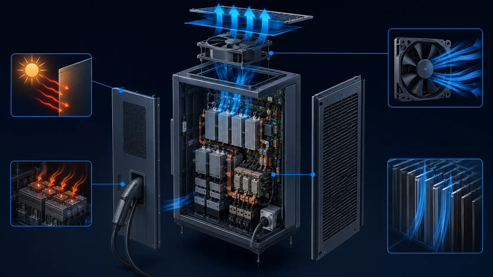
An EV fast-charger cabinet can show an acceptable average exhaust temperature while one MOSFET bank, rectifier bridge or magnetic component is running far hotter than the rest. The reason is usually not a missing fan rating. It is uneven air distribution, bypass or recirculation inside the installed enclosure.
A fan moves air through the path that offers the least resistance. If one heat sink receives a short, open route while another is behind a dense fin pack, a cable bundle or a sharp turn, the total cabinet flow can look healthy while the restricted component remains hot. An exhaust thermocouple then reports a blended result: cool air from the easy path dilutes the warm air from the critical path.
Thermal engineers should therefore separate three questions. How much heat is generated? How much air crosses the cabinet? Which devices actually receive that air at the operating point? The third question is the one that prevents a local hotspot from becoming a charging-power derating event.
Start with a heat map, not a fan count
The first design input is a map of where the cabinet converts electrical loss into heat. Name the component, estimate its loss at the worst operating point and mark the air path that is supposed to remove it.
For a simplified air-side estimate, use Q = m-dot times cp times delta-T. If a charger cabinet must reject 4.0 kW with a 15 K average air rise, air density near 1.2 kg/m3 and cp near 1.005 kJ/(kg K) imply about 0.265 kg/s, or approximately 795 m3/h. That value is the average mass-flow requirement before leakage, altitude, filter loading and non-uniform distribution are considered.
Now split the heat. Suppose 2.0 kW is in the main switching heat sink, 1.1 kW in a rectifier assembly, 0.6 kW in magnetics and 0.3 kW in control and auxiliary parts. If the switching heat sink receives only 35% of the useful flow because of a bypass path, its local temperature rise can exceed the cabinet average even though the total fan flow appears close to target.
This is why the air path should be reviewed together with the electrical loss map. A single large fan can produce a good total number and still fail a small, high-loss heat sink. Conversely, multiple smaller branches can work if each branch is balanced and the pressure drop is known. The selection decision belongs to the installed geometry, not to fan quantity alone.
| Item | Question | Useful evidence |
|---|---|---|
| Power device | Where is the highest loss at the rated duty? | Loss estimate, sensor location and heat-sink drawing |
| Magnetics | Can warm air from the transformer reach a sensitive device? | Component temperature and upstream/downstream position |
| Air branch | Does each critical heat sink receive a defined path? | Baffle layout, pressure taps or CFD |
| Outlet | Can hot air return to the inlet or a neighboring branch? | Clearance, exhaust temperature and site layout |
| Fault state | Which heat sink loses flow first? | Fan-off and filter-loaded tests |
Three airflow states that create the same-looking alarm
The animated schematic compares balanced flow, a bypass-driven hotspot and a corrected flow path. Blue particles show intended air movement; red particles show warmer or diverted air. It is a qualitative model, not a CFD result.
In the balanced state, the flow resistance of each branch is close enough that the critical heat sinks receive comparable air. In the bypass state, a low-resistance gap pulls air around the fin stack. The fan can still reach its commanded speed, and the average exhaust sensor can still look reasonable, but the local red hotspot grows at the restricted device.
The corrected state does not necessarily require a larger fan. A baffle, seal, diffuser, branch-area change or heat-sink orientation can make the existing pressure available where it matters. If the correction adds too much pressure drop, the fan must be re-evaluated at the new operating point. Geometry and fan selection must be changed together.

Why a low-resistance bypass can make a fan look healthy
The fan curve describes pressure and flow at the fan. It does not guarantee that the flow crosses the intended fin surface. A gap beside the heat sink can reduce the system resistance seen by the fan while reducing useful heat transfer.
This is a counter-intuitive failure mode. The fan may draw less current, maintain a plausible RPM and produce a comfortable exhaust temperature because the air is moving easily. The power device can still run hot because the easy air path is not the thermal path. A commissioning team that checks only RPM and total exhaust can incorrectly conclude that the fan has enough capacity.
Use smoke visualization only as a qualitative aid and keep it away from energized high-voltage hardware. For quantitative work, combine local temperature measurements with branch pressure or flow evidence. A pressure tap across the heat-sink path can show that a suspected bypass has changed the installed resistance, but it should be interpreted with the tap locations and cabinet panels documented.
The same issue appears after service. A missing foam seal, a re-routed cable, a replacement panel or a filter frame installed with a gap can change the branch resistance without changing the fan part number. Photograph the validated build state and treat the physical assembly as part of the cooling specification.
Worked example: 795 m3/h total flow but one hot device
The following numbers are an illustrative engineering example, not MEGA Tech test data. They show why total airflow and local airflow must be separated.
Assume the cabinet needs about 795 m3/h for a 4.0 kW load and a 15 K average air rise. Four fan branches provide a measured total of 780 m3/h, apparently close to the target. Branch measurements show that 45% of the flow crosses the main switching heat sink, 35% crosses the rectifier, and 20% bypasses the dense fin region through a gap near the cable entry.
The average number is only 2% below the estimated target, but the useful heat-sink flow is 624 m3/h rather than 780 m3/h. If the bypass is sealed and the flow is rebalanced so that 90% crosses the two critical heat sinks, the same total fan capacity can deliver about 702 m3/h through the thermal path. The improvement came from distribution, not a headline CFM increase.
A second check is the local temperature rise. If the main heat sink dissipates 2.0 kW and receives an illustrative 350 m3/h before correction, its local air rise is materially higher than the rectifier branch. After the branch is balanced, compare base temperature, outlet temperature and semiconductor telemetry at the same load and ambient. Do not claim a percentage improvement until the sensor locations, load duration and filter state are identical.
| State | Measured total | Critical-path share | Useful critical flow | Lesson |
|---|---|---|---|---|
| Before correction | 780 m3/h | 80% | 624 m3/h | Total flow looks close, but bypass consumes capacity |
| After seal and baffle | 780 m3/h | 90% | 702 m3/h | Geometry recovers useful flow |
| Larger fan only | 900 m3/h | 80% | 720 m3/h | More fan does not remove the bypass mechanism |
How to validate a hotspot without pretending CFD is a measurement
CFD is valuable for seeing likely flow paths and comparing geometry. It becomes trustworthy only when the boundary conditions, fan curve, material properties and validation measurements are named.
For an early design, use CFD to compare a baseline cabinet with baffle, seal, diffuser and fan-location changes. Keep the fan represented by a measured pressure-flow curve or a defensible model rather than a free-air point. If the model assumes a uniform outlet pressure, verify that the real installation has the same downstream clearance.
For a prototype, place thermocouples or RTDs at the heat-sink base, device-side hotspot, inlet air and exhaust air. If available, add pressure taps before and after the filter, across the critical heat sink and at the outlet. Log PWM, FG, current, voltage and load power on the same clock. A thermal image can help locate a hotspot, but emissivity, reflections and viewing angle must be controlled before comparing absolute values.
The purpose of validation is not to make CFD and measurement identical at every pixel. It is to confirm the direction and magnitude of the design decision: did the proposed baffle reduce bypass, did the critical branch receive more air, and did the device temperature remain within margin at the required duty?
| Stage | Good question | Do not overclaim |
|---|---|---|
| Concept | Does the proposed layout create a defined branch? | A sketch is not a validated flow result |
| CFD | Does the change reduce bypass and local recirculation? | CFD is not a substitute for the real fan curve |
| Prototype | Does the critical heat sink receive the expected flow? | One sensor cannot represent every device |
| Production | Does the assembled cabinet pass the duty and fault tests? | A fan part number does not define the enclosure result |
Choose the fan around the corrected working point
Once the geometry is corrected, re-select or confirm the fan at the new system curve. A seal or baffle can improve distribution but also raise pressure drop; a larger fan can add capacity but may increase noise, power and bearing duty.
Compare candidate fans at the pressure and flow required by the final cabinet. For each candidate, record the normal point, the loaded-filter point and the reduced-fan or service point. If the product uses PWM, verify the command range, startup behavior, FG definition and any rotor-lock alarm. If the charger is installed outdoors, add dust, moisture, salt, ambient temperature and service interval to the selection record.
Avoid selecting a fan simply because it has a larger maximum CFM. A fan with a suitable static-pressure curve can deliver more useful flow through a dense heat sink than a larger free-air-rated part that loses its margin in the cabinet. The correct comparison is the complete operating-point and hotspot result.
The relevant fan may be axial, blower or part of a hybrid liquid-air architecture. MEGA Tech's current article scope is custom DC axial cooling-fan sampling. Where the customer needs a specific high-static-pressure axial variant, voltage, connector, PWM/FG/RD behavior or a small prototype batch, those inputs can be reviewed and then validated in the customer's actual cabinet.
Turn the hotspot result into a measurable requirement before requesting quotations. For example, specify the charger load, inlet-air range, filter state, maximum heat-sink-base temperature, maximum device-to-device spread, permitted fan duty, acoustic condition and test duration. “Improve cooling” is not an acceptance criterion; a named sensor point and repeatable operating state are.
If the supplier proposes a different frame size or blade design, compare the complete assembly: mounting, seal, connector, cable route, guard, pressure curve and service access. A fan that wins on a bench but forces a new gap around the heat sink may lose in the cabinet. The quotation should therefore identify what is unchanged and what must be revalidated.
Noise and reliability follow the flow path
The same bypass that hides a hotspot can create unexpected acoustic tones, uneven dust loading and a different bearing duty. Treat the air distribution correction as a reliability change, not only a thermal change.
A narrow jet through a gap can generate a strong local noise component even when overall sound pressure is acceptable. A baffle can reduce the jet but create a new separated flow or pressure loss. Measure the installed acoustic result at the agreed working point and include the service state if the charger can remain active while a filter is dirty.
Dust loading is also uneven when branches are unbalanced. The low-resistance path may collect more contamination, while the restricted heat sink receives less air and its temperature margin falls faster. Track pressure rise over the maintenance interval and define the alarm or service action before the cabinet starts thermal throttling.
A production review should distinguish a temporary prototype fix from a durable design. Foam, adhesive seals and printed baffles need a temperature, vibration and environmental review. If the geometry is part of the airflow solution, its material, tolerance and assembly instruction belong in the production documentation.
Where MEGA Tech fits in a charger airflow review
MEGA Tech helps customers evaluate custom DC axial fan samples against the real enclosure requirement, rather than selecting from a free-air number alone.
Send the cabinet envelope, heat map, target flow, pressure estimate, fan position, filter and louver details, voltage, PWM/FG/RD requirements, noise limit, ambient range and acceptance temperatures. Photos of the assembled air path are useful because a small service gap or cable route can change the result. If a branded fan is being replaced, include its part number and the actual operating evidence instead of only its catalogue maximum.
We can help define a sample for fit, control-signal and installed thermal evaluation, including small first builds for development programs. The customer should still validate the final sample in the assembled charger because no supplier can infer every branch resistance from a fan label.
For purchasing, ask for the fan curve, test condition, current and voltage limits, connector pinout, feedback behavior, environmental range and the agreed acceptance test. This makes a lower-cost replacement a controlled engineering comparison rather than a dimension-only substitution.
A practical design review should also record the boundary of the recommendation. Custom DC axial fans can address many cabinet and power-electronics air paths, while a liquid-cooling CDU, a centrifugal blower or facility-side cooling loop may require a different system architecture. Clear scope makes the engineering discussion more credible.
Engineer FAQ: EV charger airflow distribution
These questions help separate a cabinet-average result from evidence about the critical thermal branch.
Q: Can a normal exhaust temperature prove that the power modules are cool? A: No. It can be diluted by bypass air. Measure the critical heat-sink base or device-side temperature and identify the air path that crosses it.
Q: Is total airflow more important than branch airflow? A: Total airflow sets the broad heat balance, but branch airflow decides whether a specific high-loss device receives enough cooling. Both must be checked.
Q: Should I fit a larger fan first? A: First identify bypass and restriction. A larger fan may increase useful flow, but it can also increase noise and power while leaving the low-resistance gap unchanged.
Q: What should a CFD result include? A: State the fan curve, cabinet boundary conditions, heat loads, material assumptions, filter condition and validation points. A colorful flow plot without those inputs is not an acceptance result.
Q: What does a fan supplier need to review a hotspot problem? A: Provide the heat map, cabinet layout, fan envelope, voltage, target pressure and flow, filter/louver condition, control signals, ambient range and the temperature locations that define pass or fail.
Questions for a design review
Use these questions before freezing the charger enclosure or approving a fan change.
1. Which electrical device has the highest loss at the required duty? 2. Does the measured total flow cross the critical heat sink or bypass it? 3. Are the inlet, heat-sink and exhaust temperatures logged together? 4. What pressure taps distinguish a filter restriction from a bypass path? 5. Does the final service-panel and cable layout match the validated prototype? 6. What happens after filter loading or a neighboring charger warms the inlet air? 7. Is the proposed fan compared at the actual system curve? 8. Are noise, power, bearing life and maintenance interval checked after the geometry change?
A strong review ends with a repeatable acceptance test: fixed load, fixed ambient condition, final filter and panel state, defined sensor locations, a stabilization period and a record of fan command, feedback, pressure and temperatures. That record is more valuable than a single maximum CFM number.
Validate the critical branch, not only the average
An EV charger cooling system is ready when the critical power devices remain within margin at the real installed working point, after the expected filter, service and ambient conditions are applied.
If you are reviewing a charger cabinet with a local hotspot, share the heat load, enclosure photos, air path, fan part number, pressure target, voltage, control signals and acceptance temperatures. MEGA Tech can help structure a custom DC axial-fan sample and a measurement plan around the actual branch that needs cooling.
Continue with the EV and automotive cooling applications or read the EV charger fan redundancy and reverse-flow guide.