The Charger Can Be Thermally Safe at Noon and Fail at Dawn
Outdoor EV chargers see a different fan problem during a cold, humid restart than during a dry hot-day power test.
A high-power EV charger may pass a summer thermal test and still develop a field problem after a cold night. The cabinet is de-energized or held at standby, the metal enclosure follows outdoor temperature, humidity rises, and a first charge session starts while the fan, filter and power modules are still cold. When the cabinet warms, condensation risk changes again. The fan must start reliably, move air through its real filter and grille, and avoid turning a moisture problem into a false alarm.
IEC 61851-1 covers operating conditions and safety requirements for EV supply equipment. ABB's Terra 360 documentation illustrates why environmental details matter: outdoor operation can include a wide temperature range, humidity, condensation and ice conditions, with a heater recommended in harsh low-temperature conditions. These are charger-system requirements, not a universal fan rating, but they define the environment that the fan sample must survive.
This article focuses on air-cooled and hybrid EVSE cabinets. It connects low-temperature start, moisture, salt or dust, power-stage heat, filter pressure, PWM control, FG/RD feedback and service evidence. The examples are engineering estimates for design discussion, not a customer result or a guaranteed MEGA product rating.
Separate Temperature, Humidity and Charging Power States
The thermal test matrix should connect environmental history to the first charging event, not only record steady-state cabinet temperature.
Define at least cold soak, cold standby, first charge, continuous rated charge, reduced-power charge and hot restart. Record cabinet metal temperature, air temperature, relative humidity or dew-point estimate, power-stage temperature, fan command, fan feedback and filter pressure. If a heater or anti-condensation strategy exists, record its state and the time from energization to fan start.
As an illustrative estimate, consider a charger with 42 kW DC output and 96% conversion efficiency. The conversion loss is approximately 42 x (1/0.96 - 1) = 1.75 kW. Add 180 W from control, cable, display and auxiliary electronics and the cabinet heat load is about 1.93 kW at rated output. With an allowed 15 K air rise, air density 1.15 kg/m3 and cp 1005 J/(kg K), the starting airflow is approximately 1.93 kW/(1.15 x 1005 x 15) = 0.111 m3/s, or about 400 m3/h before pressure loss and margin.
Do not use that number for cold-start control. The required fan airflow and the required fan starting behavior are separate questions. A fan can deliver the required warm-state operating point but need a higher startup command or a different bearing and control strategy at low temperature.
Also state the air-density basis for the calculation. Cold air is denser, but the enclosure heat balance, fan curve and pressure measurement may be reported under different conditions. Keep the mass-flow and volume-flow assumptions visible in the test report, and do not compare two fan curves without checking temperature, altitude, pressure reference and measurement method.
| State | Record | Question |
|---|---|---|
| Cold soak | cabinet temperature, dew point and fan supply voltage | What is the starting condition? |
| First charge | startup time, fan current, FG/RD and local temperature | Does the fan start before the power stage heats? |
| Rated charge | power loss, airflow, filter pressure and heat sink | What is the steady working point? |
| Wet-to-warm transition | humidity, condensation observation and heater state | Does warm-up create moisture risk? |
| Loaded path | filter pressure, fan duty and power derating | What is the service-limit margin? |
Calculate Airflow, Then Test the Filtered Cabinet Curve
Heat balance gives the starting airflow; the fan P-Q curve decides whether that flow exists through the real EVSE cabinet.
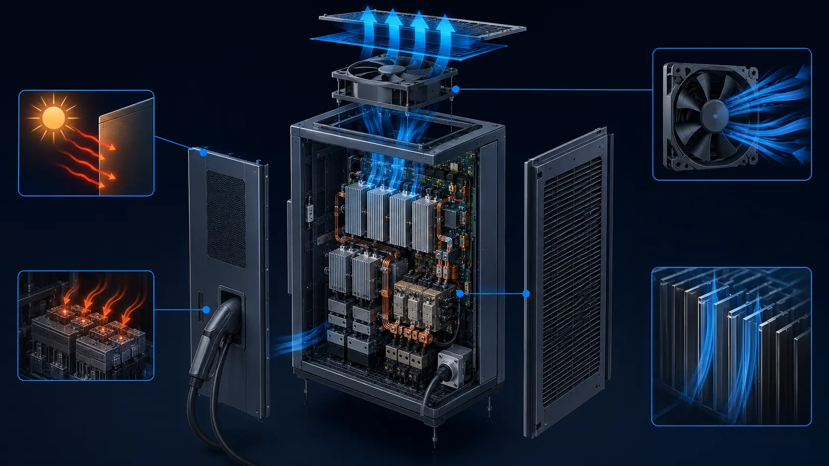
Map the air path from the outdoor grille through the filter, power module heat sinks, busbar clearance, cable routes and exhaust. An illustrative clean path may contain 38 Pa at the inlet grille, 45 Pa at the filter, 72 Pa across the power-stage heat sinks, 32 Pa at the guard and 28 Pa at the exhaust transition: about 215 Pa total. If salt or dust loading adds 55 Pa, the service state becomes approximately 270 Pa.
The fan must be checked at the required airflow at both pressure values. A free-air 400 m3/h value does not prove that the cabinet receives 400 m3/h at 215 or 270 Pa. If a fan is selected close to the pressure knee, a small change in filter loading can create a large airflow change. A larger axial fan at moderate speed may improve acoustic and bearing margin, while a compact blower may fit a tight high-pressure duct.
Measure useful airflow where it crosses the power module. Exhaust temperature alone can be misleading if the filter frame leaks or a cable opening bypasses the heat sink. Use smoke or tufts during commissioning and repeat with the service panel, gasket, grille and adjacent charger cabinets installed.
Animated Model: Cold Start, Dew Point and Heat-Up
The schematic shows why a fan command, a moisture state and a power-stage temperature must be tested together.
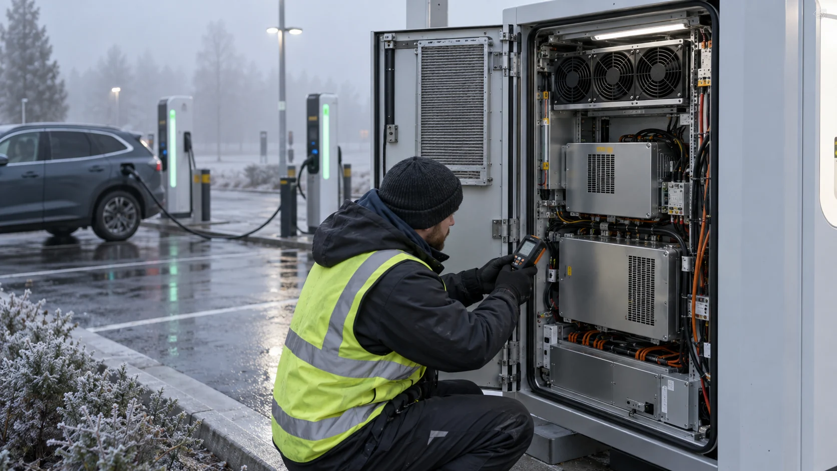
Use three physical tests: cold start after overnight soak, humid warm-up with the cabinet initially de-energized, and rated charging after the enclosure reaches its operating temperature. Measure the fan start time, voltage, current, FG/RD, local dew point and the temperature of the power-stage heat sink. If a heater is used, record when it enables and whether the fan is allowed to run before moisture conditions are controlled.
The animation is not a condensation calculation or a universal control sequence. It is a reminder that moving cold humid air through a colder cabinet can have a different result from moving warm dry air. The equipment manufacturer must define the moisture protection, insulation, heater and safe charging behavior.

Low-Temperature Fan Start Is an Interface Problem
A fan sample must start at the actual voltage, temperature, control duty and mechanical orientation that the charger provides.
Check minimum supply voltage at the fan connector during contactor closure and power-stage startup. Cable length, fuse resistance and a shared DC bus can create a short voltage dip. Record locked-rotor current, startup time, minimum starting voltage and the time until FG becomes valid. Repeat at the lowest ambient temperature and after the fan has been idle long enough for the bearing and frame to reach the cabinet temperature.
PWM control needs the same attention. Test startup boost, minimum stable duty, control frequency, ramp rate and recovery after a brownout. A low command can be quiet but below the fan's stable region. A full-speed command can create a current transient or a pressure shock in a damp filter. If the charger controller uses a temperature curve, add hysteresis and a minimum run time so the fan does not hunt around a threshold. Check the control signal with the fan mounted in the final orientation; wiring length, pull-up behavior and grounding can change the interface seen by the motor controller.
Do not treat FG as proof of cooling. It confirms a rotational signal, not airflow through the filter or heat sink. Pair it with pressure, temperature and useful airflow evidence.
A useful startup record has a one-second or faster time base around contactor closure. Capture supply voltage at the fan, current, PWM command, FG pulse arrival, heater status and the first temperature rise of the power module. Compare a cold-soaked start with a warm restart. If the controller waits for a temperature alarm before enabling the fan, the test may be measuring a control delay rather than a fan capability. Define the order explicitly: moisture protection, fan startup, feedback confirmation, power enable and charge-current ramp.
Condensation, Salt Fog and Filter Maintenance
Outdoor protection starts with the enclosure boundary and service method, not with an IP label on the fan alone.
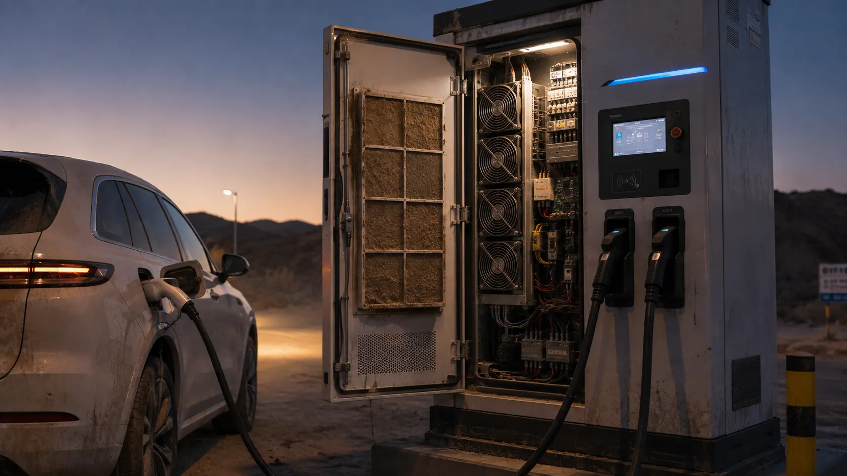
Inspect the inlet, exhaust, door gasket, cable gland, drain, pressure equalization path and heater placement. A protected fan cannot compensate for a cabinet seam that draws humid air directly onto a cold power module. Salt fog and road dust can also change filter pressure and degrade connectors or bearings over time. Define whether the fan is inside a protected compartment or exposed to the outside air path.
Use differential pressure across the filter and record the service-limit value. A fan can keep its commanded RPM while useful airflow collapses. A temperature alarm may arrive too late if the power stage has a short thermal time constant. Combine filter pressure, fan current, FG/RD, inlet temperature and power-module temperature in the maintenance record.
Repeat the pressure and thermal measurements after the cabinet has experienced the intended salt, dust and rain exposure. Do not assume that a dry laboratory restriction represents a wet or salt-loaded filter: water film, corrosion products and trapped debris can change both pressure and airflow direction. Inspect the fan frame, connector, guard and drain path after the exposure, then run a startup and feedback check before returning the charger to service.
ABB's Terra 360 environmental guidance warns that outdoor EVSE may encounter condensation and ice and recommends a heater in harsh low-temperature, high-humidity conditions. That is a charger-system example, not a universal fan requirement. The transferable engineering point is to validate the fan, heater, filter and enclosure as one environmental system.
Power Derating and Thermal Feedback
A charger should reduce current deliberately when the air-side working point or environmental condition removes thermal margin.
CharIN's MCS recommendations separate vehicle thermal responsibility from EVSE thermal responsibility and state that the EVSE must meet its own temperature limits. The same principle applies to a DC fast charger: connector, power module, cable, cabinet and fan controls need defined limits. If the fan or filter cannot maintain the air-side target, the charger should derate or enter a controlled state rather than silently continuing at full power.
Use temperature and pressure as feedback, not only output power. A 150 kW charger may be thermally comfortable at 20°C and need current reduction at 40°C, but a blocked filter can create the same local heat rise at a lower ambient. Log fan duty, FG/RD, filter pressure, inlet temperature, power output and heat-sink temperature with the derating decision.
A practical control sequence is to increase fan duty before the heat sink reaches its warning limit, apply hysteresis to prevent oscillation, and use a separate hard protection threshold. Validate recovery when the ambient falls or the filter is replaced. Record whether the charger returns to full current automatically or requires a service acknowledgement; the thermal controller, charger firmware and site operator should have the same expectation.
An Anonymous Customer Scenario: Cold Morning Derating at a Highway Site
A European charging-network integrator found that its cabinet passed a warm-day load test but delayed the first morning session after a humid cold night.
The charger used filtered intake air and two compact axial fans. During a warm laboratory test, the fans reached the commanded speed and the power modules remained within their target. At the outdoor site, the cabinet was cold and damp after overnight standby. The first fan started slowly, FG feedback arrived late, and the controller reduced charging power. The filter also had higher pressure after several weeks of road dust and salt exposure.
MEGA Tech reviewed the minimum fan voltage, startup profile, filter pressure, heater timing, enclosure drain and local temperature sensors. A pressure-matched fan sample was tested with the final filter and grille. The control sequence was changed to verify fan startup before enabling the highest power stage, while the service procedure added a differential-pressure check.
The customer repeated cold soak, humid warm-up, first charge, rated charge and blocked-filter tests. The release record connected fan current, FG/RD, dew point, power derating and local heat-sink temperature. The improvement was not claimed as a universal cold-weather performance number; it was a documented operating sequence for the customer's cabinet.
The team also compared the cabinet with the service filter fitted, the filter removed for inspection and the door opened only for diagnosis. The open-door result was useful for locating the hotspot but was excluded from the release decision. The production acceptance point used the final gasket, grille, cable routing and drain arrangement. This distinction prevented a visually impressive but non-repeatable laboratory result from becoming the field specification.
This is an anonymized engineering scenario, not a public customer result. The transferable lesson is to test the first charge after environmental soak, not only the steady-state charger after the cabinet is already warm.
| Test | Measurements | Decision |
|---|---|---|
| Cold soak | cabinet temperature, voltage, fan current and start time | confirm startup margin |
| Humid warm-up | dew point, heater state, condensation observation and fan duty | confirm moisture strategy |
| Rated charge | power loss, pressure, airflow and heat-sink temperature | confirm steady working point |
| Loaded filter | differential pressure, FG/RD and derating response | define service limit |
| Fault injection | fan stop, feedback loss and controlled power reduction | confirm protective behavior |
How MEGA Tech Supports Outdoor EV-Charger Fan Projects
We help EVSE teams match a fan to the real air path, environmental cycle and production interface.
MEGA Tech develops custom DC axial fans and compact centrifugal blowers for EV fast chargers, power modules, charging cabinets and auxiliary thermal systems. We review the installed P-Q point, clean and loaded filter pressure, startup at low voltage and temperature, PWM or voltage control, FG/RD feedback, connector, fan direction, bearing choice, vibration, salt or dust exposure, acoustic target and quantity.
For a first review, provide heat loss by charging state, required airflow and static pressure at that airflow, minimum and maximum ambient, humidity or dew-point conditions, filter data, heater strategy, voltage tolerance, control interface, feedback requirement, fan envelope, noise target, service interval and quantity. A short outdoor thermal log is more useful than maximum CFM alone.
We can also evaluate cost-competitive replacements for Sanyo Denki, SUNON, Delta, NMB and ebm-papst when the replacement is verified at the same installed pressure, voltage, mounting, feedback and environmental condition. We do not supply the EVSE power module, charging protocol, heater, moisture protection system or safety approval. We support the fan and supplied air path from sample to production validation.
Engineer FAQ: EV Fast-Charger Fan Selection in Cold Weather
Short answers for an outdoor EVSE thermal review.
Q: Can a fan be selected from charger kW alone? A: No. Convert efficiency loss into the air-side heat boundary and check the installed pressure, ambient temperature and service-state filter condition.
Q: Does IP rating guarantee cold-weather fan startup? A: No. Test minimum voltage, temperature, control duty, bearing behavior and FG timing at cold soak, then repeat after humidity, salt or dust exposure.
Q: Can fan RPM prove the filter is healthy? A: No. Measure filter differential pressure, useful airflow and local power-module temperature at the service limit.
Q: Does a heater remove the need for fan validation? A: No. Heater timing, airflow, condensation and charging enable logic must be tested together, including the transition from heater-only standby to active charging airflow.
Q: What should we send for a custom sample? A: Provide heat loss, airflow and static pressure at that airflow, voltage, startup condition, filter pressure, control, feedback, environment, noise target and quantity. Include cold-soak duration, heater timing, service filter condition and the exact power-enable sequence so the sample is tested against the real charger behavior during commissioning and release review.
Questions for the Design Review
Use this checklist before releasing an outdoor EV charger fan or replacement.
- What is the coldest and most humid fan-start condition after overnight standby?
- Does the fan start at the actual connector voltage and reach valid FG before high power is enabled?
- What are the clean and service-limit filter pressure drops at the required airflow?
- Have dew point, heater state, drain path and cabinet warm-up been tested together?
- Does the fan meet the working point at the highest ambient and lowest permitted voltage?
- What happens when the fan stops, FG is lost or the filter pressure exceeds the limit?
- Is the derating decision tied to local heat-sink temperature and air-side evidence?
- What exact P-Q, filter, startup and environmental information will be sent for the sample?