Outdoor EV Chargers Fail at the Air Path Before the Datasheet
A fast charger can meet its power target in a clean lab and still derate in a dusty, coastal or industrial installation.
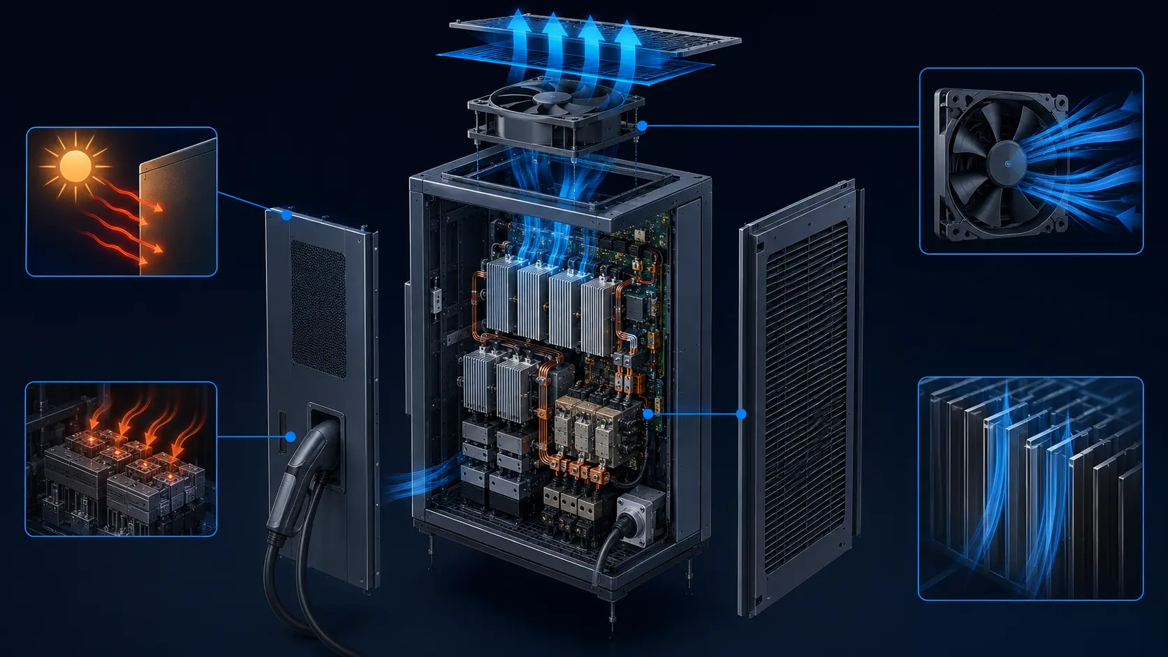
High-power DC fast chargers convert substantial electrical energy inside a compact outdoor enclosure. Rectifiers, PFC stages, DC-DC modules, capacitors, busbars and control electronics reject heat, while the charger must remain serviceable in dust, rain, salt-laden air and changing ambient temperatures. The cooling fan is therefore not an isolated part; it is one element in an air path that includes the filter, grille, heat exchanger, power modules and exhaust opening.
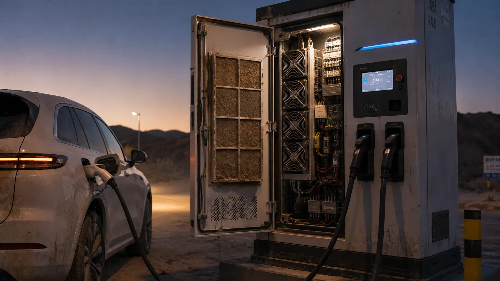
When dust loads the intake filter, the pressure drop rises and the fan operating point moves to lower useful airflow. When salt mist or chemical particles reach the enclosure, corrosion and conductive contamination can damage the fan, heat exchanger, connectors or power electronics. If the control system responds only to fan RPM, it may report normal rotation while the charger has already lost thermal margin.
This guide gives a practical validation method for outdoor EV charger fan selection. It covers pressure, filter loading, salt-fog exposure, IP boundaries, PWM or EC control, power derating and maintenance. Product safety, electrical isolation and the applicable EVSE standards remain the responsibility of the charger OEM and qualified service team.
Start With the Charger Heat and Airflow Boundary
Before selecting a fan, identify which power modules are cooled by air and what temperature or power limit triggers derating.
Map the rectifier, PFC, DC-DC, capacitor, control and cable compartments. Record their loss at standby, normal charging and the maximum continuous operating state. A charger may have multiple air zones or a liquid-cooled cable while the cabinet electronics remain air cooled. Do not calculate fan flow from the charger output power alone; the conversion loss and the actual air-side heat path determine the requirement.
For an illustrative estimate, if a 180 kW charger has 96% conversion efficiency, the total loss is about 7.2 kW. If 5.4 kW of that loss enters the air path and the design accepts a 12°C air rise, the estimated mass flow is 5,400/(1,005 × 12) = 0.45 kg/s. Convert to volumetric flow using the actual air density, then add the installed pressure and control margin. The example is a method, not a universal charger specification.
Identify the component that reaches its limit first. If a power module derates at a lower temperature than the rest of the cabinet, the sensor and control response must protect that module. A room or exhaust sensor can be useful for system control, but it cannot replace a local measurement where the thermal limit actually occurs.
| Input | Example evidence | Why it matters |
|---|---|---|
| Air-side loss | module loss map at charging states | sets the thermal airflow requirement |
| Limiting component | temperature threshold and derating curve | sets sensor location and control priority |
| Air path | filter, heat exchanger, grille and exhaust | sets the system pressure curve |
| Environment | ambient, RH, dust, salt and water exposure | sets fan construction and maintenance |
| Control interface | PWM, voltage, FG/RD and alarm behavior | sets the usable operating range |
Filter Pressure Is a Charger Performance Variable
A filter is not only a protection part; its pressure drop changes the airflow that reaches the power modules.
Measure the filter pressure in the installed frame, with the intended gasket and bypass seals. Record the clean pressure, the maintenance threshold and the representative loaded pressure. A filter that looks acceptable by visual inspection may have a pressure drop that consumes the fan's control headroom, while a filter with a low pressure drop may allow corrosive or conductive particles to reach the electronics if its efficiency and sealing are unsuitable.
For a worked estimate, suppose a clean filter contributes 38 Pa, the heat exchanger 72 Pa, the inlet grille 24 Pa, internal module passages 44 Pa and the exhaust louvre 28 Pa. The clean installed pressure is about 206 Pa. If filter loading adds 42 Pa, the service-state pressure becomes approximately 248 Pa. The candidate fan must be checked at both points, and the charger controller should know when the service state is no longer thermally acceptable.
Do not use an RPM alarm alone. Add differential pressure, airflow estimation or a thermal-spread check. If the fan remains at the commanded speed but the power-module inlet temperature rises, the system needs a maintenance or derating response. The exact threshold should be validated on the final charger, not copied from a generic filter catalogue.
Interactive: Watch Dust Loading Steal the Operating Point
The schematic shows the fan curve moving to a lower-flow point as the filter restriction rises, even while the fan continues to rotate.
Use the animation to define three test states: clean filter, loaded filter and restricted or bypassed filter. At each state record fan command, current, FG/RD feedback, differential pressure, power-module temperature, exhaust temperature and charger output. If the charger derates, record the exact trigger and recovery behavior rather than reporting only that the fan was running.
The same method applies when the filter is replaced by a finned heat exchanger or a liquid-to-air coil. The air-side resistance and fouling condition still affect the fan operating point. A high-pressure fan may preserve airflow, but it may also increase noise and input power; compare the full operating envelope instead of choosing the largest motor.
This is a qualitative engineering model, not a measured charger curve. The purpose is to make the maintenance and selection question visible before a site experiences repeated power derating.

Salt Fog Changes Reliability Without Immediately Changing RPM
Corrosion, deposits and moisture can reduce fan life or create electrical risk before a controller detects an airflow fault.
Coastal and de-icing-salt environments expose the charger to chloride-bearing moisture. Industrial sites can add chemical vapors, conductive dust or cleaning aerosols. The fan frame, guard, impeller, motor electronics, bearings, connector and cable exit may need different protection strategies. An enclosure IP rating does not automatically certify every internal fan or connector, and a coated frame does not guarantee that the PCB, bearing or fasteners have the required resistance.
Define whether the fan sees filtered dry air, humid air, direct spray, condensation, salt mist or periodic washdown. Check material compatibility, coating, fastener choice, connector sealing, drainage and the position of the fan relative to the intake. Avoid a layout that makes the fan a collection point for water or salt residue.
Use a representative environmental test plan and inspect after exposure: startup, current, speed, alarm, vibration, noise, insulation or electrical leakage as appropriate, and installed airflow. The exposure method and acceptance criteria should be agreed with the charger OEM and applicable qualification process; do not treat a short salt-fog screen as a lifetime guarantee.
Control Fan Speed With Charger Power and Temperature Together
A power-aware control loop can reduce energy at partial load, but temperature and airflow feedback still protect the limiting module.
During low-power charging, a fixed maximum fan command wastes energy and increases noise. During high-power charging, a slow or poorly placed sensor can delay the response. Use charger power as a feed-forward signal and component temperature, differential pressure or airflow as feedback. Validate minimum stable PWM or EC duty, startup, tachometer feedback, rotor-lock alarm, restart and transition between charging states.
For an illustrative energy comparison, four 24 V fans drawing 0.30 A each use 28.8 W at full command. If the controller uses 0.16 A for 70% of a 12-hour operating window and 0.30 A for 30%, the average fan input is about 19.2 W, or 230 Wh over that window. This is a fan-input estimate only; the impact on charger efficiency, power derating and site HVAC must be measured separately.
Do not let a software control loop hide a blocked filter. If the fan reaches its maximum command and the power module remains hot, create a clear service or output-derating action. The alarm should communicate whether the cause is high ambient, filter pressure, fan feedback, sensor failure or a power-module thermal limit.
Validate Normal Charging, Derating and Maintenance States
The charger should be tested at the conditions that service teams and drivers will actually encounter.
Run the charger at standby, partial power and maximum continuous power. Repeat with a clean filter and the defined service-state restriction. Include a hot ambient, high humidity or coastal condition where relevant. Record time to stable temperature, fan command, current, pressure, component temperature, output power and recovery after the load is reduced.
Test the fan fault and sensor fault separately. A stopped fan may require controlled power reduction, while a failed pressure sensor may require a safe fallback command. Confirm the charger does not continue to advertise full output when its cooling evidence is invalid. The precise behavior belongs to the charger safety and control design, but the fan supplier should provide the feedback and operating data needed by that design.
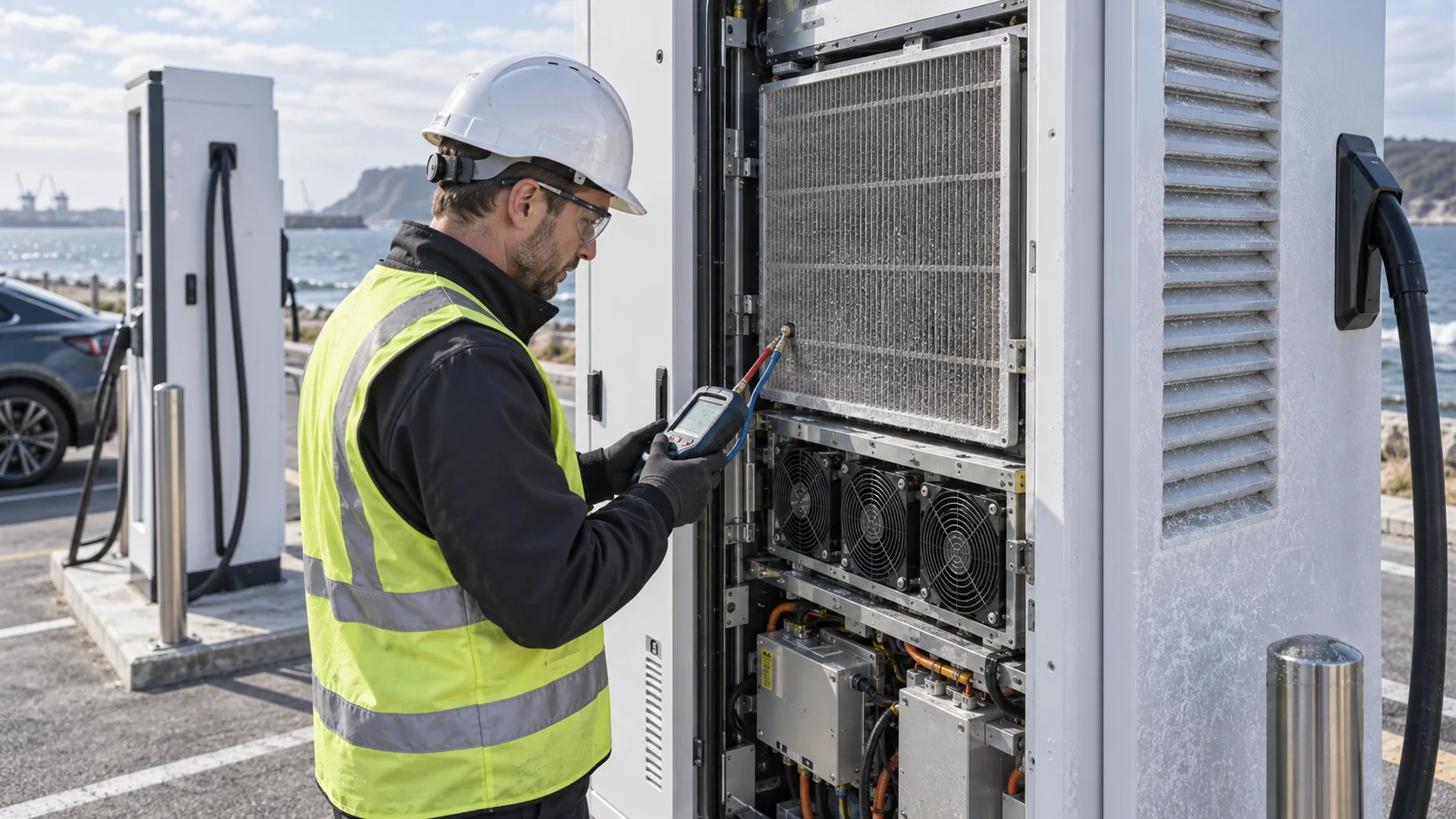
For maintenance, verify filter removal, gasket replacement, connector access, fan replacement, torque, cleaning method and post-service functional test. Manuals for commercial DC chargers commonly call for periodic filter inspection or cleaning; the interval should be adapted to site dust, charge cycles and corrosion exposure rather than copied blindly.
| State | Measurements | Release question |
|---|---|---|
| Standby / low power | fan duty, noise and stable start | does the fan avoid unnecessary maximum speed? |
| Normal fast charge | pressure, flow, module temperatures | does the air path meet the installed duty? |
| High ambient | intake temperature and derating response | is thermal margin based on real inlet air? |
| Loaded filter | filter DP, fan current and output power | does maintenance happen before derating? |
| Fan or sensor fault | alarm, fallback and controlled output | does the charger fail safely and clearly? |
An Anonymous Customer Example: Coastal Charger Derating After Filter Loading
A European charging-network integrator saw repeated output reduction at a coastal fleet site even though the fans reported normal RPM.
The chargers passed a clean-cabinet thermal test and operated normally after installation. Several months later, the site reported that output power reduced during hot afternoon charging sessions. The fan feedback remained present, but the power-module temperature rose faster than expected. Inspection found a combination of fine dust and salt residue on the intake filtration and heat-exchanger surface.
MEGA Tech reviewed the fan envelope, installed pressure, filter frame, voltage and PWM interface, connector exposure, corrosion requirements and service access. The team compared the existing fan with a higher-pressure custom sample at clean and loaded restrictions, then measured the module inlet temperature and output power at the same charging profile.
The sample preserved more useful airflow at the defined loaded pressure, but the larger improvement came from the maintenance threshold and filter sealing. The customer added a differential-pressure check, revised the cleaning interval for the coastal site and kept a temperature-based output limit as a protective fallback. The fan specification was updated to include the environmental and service state instead of only the clean-state CFM.
This is an anonymized engineering scenario, not a published customer performance claim. The transferable lesson is that fan replacement, filter design, sealing and maintenance must be qualified as one thermal system.
Where MEGA Tech Fits In
We help EV charger teams develop a fan sample around the real pressure, environment, control interface and derating requirement.
MEGA Tech can review custom axial fans, compact blowers and fan modules for DC fast-charger cabinets, rectifier compartments, heat exchangers, liquid-cooling CDU air sides and control enclosures. The review can include P-Q behavior, filter loading, PWM or voltage control, FG/RD feedback, IP and corrosion exposure, salt-fog requirements, noise, vibration, bearing life, connector and cable exit and small-batch sampling.
For a first review, provide charger power and loss data, module temperature limits, cabinet drawing, filter and heat-exchanger pressure data, outdoor temperature and RH range, dust or salt exposure, voltage, control signal, feedback requirement, noise limit, maintenance interval and expected quantity. A service photo showing the loaded filter or corroded grille is valuable because it identifies the actual failure mechanism.
We also support cost-competitive replacements for Sanyo Denki, SUNON, Delta, NMB or ebm-papst fans when the replacement is verified at the same installed pressure, environmental condition, electrical interface and charging state. A replacement should be demonstrated by measured cooling and derating behavior, not by a similar frame size alone.
Engineer FAQ: Outdoor EV Charger Cooling Fans
These questions connect outdoor reliability to the installed fan and filter duty.
Q: Can an IP-rated charger ignore the intake filter? A: No. IP protection, filtration, pressure drop and maintenance are separate parts of the air-path design.
Q: Does normal RPM prove that the charger has enough airflow? A: No. A loaded filter or blocked heat exchanger can reduce useful airflow while the fan continues to rotate at the commanded speed.
Q: What matters more in a coastal site, IP rating or corrosion testing? A: Both address different risks. Review the full enclosure, fan, connector, fastener, filter and drainage arrangement under the actual exposure.
Q: Should the fan run at full speed during every charging session? A: Not necessarily. Use a validated PWM or EC curve tied to charger power and limiting component temperature, with a clear high-temperature fallback.
Q: How often should an EV charger filter be cleaned? A: There is no universal interval. Use site dust, salt, charge cycles, filter pressure and thermal data to set the service plan.
Q: Can MEGA Tech replace a premium charger fan? A: Yes, when the replacement is matched and tested at the same pressure, control, environment, acoustic condition and derating state.
Q: Can you support a small pilot build? A: Yes. We can adjust fan parameters and interfaces, build samples and support thermal, pressure, noise and environmental validation before production.
EV Fast-Charger Fan Review Checklist
Use this list before freezing a fan, filter, control curve or maintenance interval.
- Is the air-side heat load separated from charger output power?
- Is the limiting power-module temperature and derating curve known?
- Were grille, filter, heat exchanger, internal path and exhaust losses included?
- Was the fan compared at clean and service-state pressure?
- Were dust, salt mist, condensation, cleaning spray and drainage considered?
- Were PWM/EC minimum duty, FG/RD feedback, startup and restart checked?
- Was a hot-ambient and loaded-filter charging test completed?
- Were fan, pressure-sensor and temperature-sensor faults tested separately?
- Were noise, vibration, bearing life, connector and maintenance access checked?
- Are measured values, estimates, OEM limits and standards clearly separated?