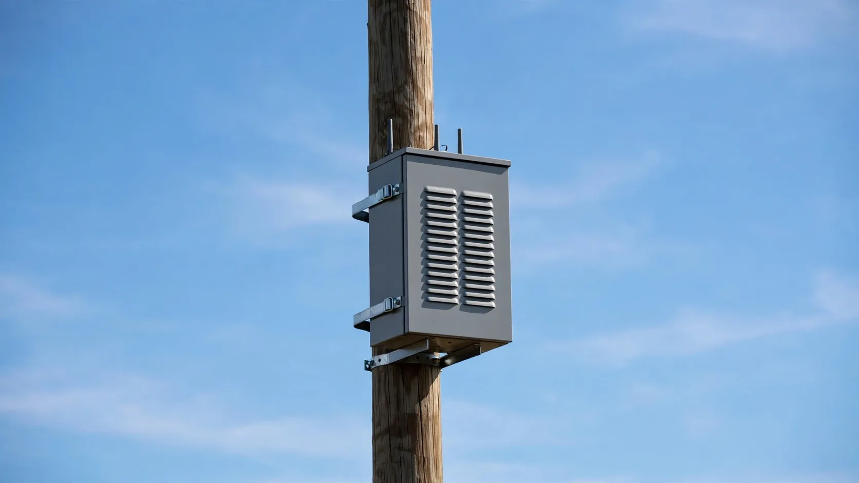
A 24 litre cabinet on a pole is not a small 5G cabinet
Pole-mount micro cabinets carry 30 to 150 W of electronics, hang a metre from a bedroom window, and are serviced by a van that costs more per visit than the fan inside them. Those three facts decide the fan - not the heat load.
Outdoor 5G cabinet practice does not scale down. A standard street cabinet gives you 600 litres, a door large enough for an 80 mm fan tray or a heat exchanger, and a maintenance contract that visits anyway. A pole-mount micro cabinet gives you 15 to 40 litres, a door that fits one small frame at most, and a site count in the thousands where every unplanned visit is the dominant cost of ownership.
Three consequences follow. The heat load is small enough that airflow is rarely the problem, but the enclosure is sealed to IP55, so every gramme of air is pushed through a screen, a louver and a filter. The site is dense and unattended, so fan life is measured against a decade of continuous duty, not a five-year service interval. And the cabinet hangs at eye level in a residential street, which makes surface finish and noise part of the thermal design.
Every number below is worked from a single reference cabinet so the arithmetic can be checked: 400 mm high, 300 mm wide, 200 mm deep, 24 litres, 0.52 m2 of external surface, 0.20 m2 of that sunlit at midday, 120 W of internal dissipation, 40 C ambient, 65 C maximum internal air.
Fix the climate class before you open a fan datasheet
The fan is the last decision in this duty. The first is which environmental class the site is specified to, because it sets the ambient, the solar load, the altitude and the cold-start corner in one document.
ETSI EN 300 019-1-4 classifies stationary use at non-weatherprotected locations: class 4.1 covers the temperate case, class 4.1E extends it to colder and wetter sites. Both carry numeric limits that map directly onto fan selection, so the class should appear on the thermal specification before any airflow is calculated.
Two rows in that table catch designs out. The high air temperature of +40 C or +45 C is the ambient your fan and its bearing live at continuously, which is above the 40 C condition most catalogue L10 figures are quoted at. And the low air pressure of 70 kPa - the standard notes it corresponds to about 3000 m - removes roughly 30 per cent of air density, which has to be paid back in volume flow.
The solar radiation row is 1120 W/m2 in both classes. It is the same figure used by IEC 60068-2-5 Test Sa, and on a 24 litre cabinet it is the largest single term in the heat budget.
| Parameter | Class 4.1 | Class 4.1E | What it drives |
|---|---|---|---|
| Low air temperature | -33 C | -45 C | Bearing grease, cold-start torque, condensation |
| High air temperature | +40 C | +45 C | Available temperature rise, fan ambient rating |
| Solar radiation | 1120 W/m2 | 1120 W/m2 | Surface absorptivity, shade, wall heat gain |
| Relative humidity | 15 to 100 % | 8 to 100 % | Condensation, drain path, corrosion class |
| Rain intensity | 6 mm/min | 15 mm/min | Louver geometry and IP rating of the inlet |
| Air pressure | 70 to 106 kPa | 70 to 106 kPa | Air density and volume-flow margin (70 kPa is about 3000 m) |
| Movement of surrounding air | 50 m/s | 50 m/s | External film coefficient, wind-driven infiltration |
Solar load, not equipment loss, sets the baseline
On a cabinet this small the sun delivers more heat than the electronics do. Paint colour and a shade are thermal components with a watt rating, and they should be selected before the fan.
The standard way to carry solar load into a thermal calculation is the sol-air temperature: the absorbed radiation converted into an equivalent rise of the effective ambient seen by the surface. For a sunlit face the rise is absorptivity times irradiance divided by the external film coefficient, so with 1120 W/m2 incident and a film coefficient of about 15 W/m2K in a light breeze, a dark grey face at 0.8 absorptivity gains close to 60 K of sol-air rise.
Only part of the cabinet is sunlit at any moment, so the rise has to be weighted by area. At midday the top face and one side are exposed: 0.20 m2 of the 0.52 m2 total, a ratio of 0.385. Applied to the sol-air figure, that gives an effective ambient rise of about 23 K for dark grey, 14 K for mid grey and 9 K for white - before any shade is fitted.
The absorbed power is worth stating on the drawing as well, because it is the number that makes the argument. Absorbed solar power is absorptivity times irradiance times sunlit area: 179 W for dark grey against 67 W for white on the same cabinet. If the electronics dissipate 120 W, the finish is worth more than a whole second fan.
A shade changes the area term rather than the absorptivity: halving the sunlit area halves the absorbed power, and a white cabinet with a shade sits at about 34 W absorbed and 4 K of effective rise - close enough to a shaded indoor enclosure that the rest of the design becomes conventional.
| Surface finish | Absorptivity | Absorbed power | Effective ambient rise | Effective ambient at 40 C |
|---|---|---|---|---|
| Dark grey paint | 0.8 | 179 W | 23 K | 63 C |
| Mid grey paint | 0.5 | 112 W | 14 K | 54 C |
| White or light grey | 0.3 | 67 W | 9 K | 49 C |
| White with a shade halving sunlit area | 0.3 | 34 W | 4 K | 44 C |
What the walls carry without a fan
Before sizing any airflow, work out how much of the load the enclosure surface rejects on its own. On a small cabinet in full sun the answer is close to nothing, which is the whole point of the section.
Heat leaving through the walls is the product of an overall coefficient, the surface area and the temperature difference available. For a single-wall plastic or steel cabinet with natural convection inside and out, an overall coefficient around 6 W/m2K is a reasonable planning figure; a double wall with 25 mm of insulation drops it towards 1.5 W/m2K, which helps against solar gain and hurts against internal loss at the same time.
The available temperature difference is where solar load does its damage. It is not the internal air temperature minus the ambient - it is the internal air temperature minus the effective ambient, which the previous section raised by 23 K in the dark grey case. With a 65 C internal limit and a 40 C day, a dark grey cabinet has 2 K left to work with, so 0.52 m2 at 6 W/m2K rejects about 6 W. The same cabinet in white has 16 K available and rejects about 51 W.
That is the result worth carrying into the rest of the design: on the dark cabinet the walls are effectively out of the game, and every watt the electronics make has to leave with the air. On the white cabinet the walls remove roughly 40 per cent of the internal load before a single fan is switched on.

The heat budget, computed for both finishes
Putting the last three sections together gives one table that can be checked by hand and pasted into a specification.
The two cases below differ only in surface absorptivity. Everything else - the cabinet, the 120 W of electronics, the 65 C internal limit, the 40 C ambient - is identical, and the difference in required airflow is a factor of about 1.7.
| Item | Dark grey, absorptivity 0.8 | White, absorptivity 0.3 |
|---|---|---|
| Internal dissipation | 120 W | 120 W |
| Solar absorbed on sunlit faces | 179 W | 67 W |
| Effective ambient | 63 C | 49 C |
| Wall rejection at 65 C internal | 6 W | 51 W |
| Heat the fan must remove | 114 W | 69 W |
| Air mass flow at a 15 K air rise | 27 kg/h | 16 kg/h |
| Volume flow at 40 C and sea level | 24 m3/h (14 CFM) | 15 m3/h (8.6 CFM) |
| Volume flow corrected to 70 kPa | 35 m3/h (21 CFM) | 21 m3/h (13 CFM) |
Size the airflow by mass flow, then correct for altitude
Required air mass flow depends only on watts and the allowed temperature rise. Delivered mass flow depends on density. Both should be on the drawing, because the second one changes with altitude and season.
Required mass flow is the heat to remove divided by the specific heat of air and the allowed rise between inlet and exhaust: 114 W over 1005 J/kgK and 15 K gives about 27 kg/h. That number is fixed by the hardware and the temperature limit, and nothing about the fan can change it.
Delivered mass flow is what the fan actually moves, and it falls with density. A fan rated at 24 m3/h moves 27 kg/h at sea level and 40 C, but only about 19 kg/h at 70 kPa and the same temperature - a shortfall of roughly 30 per cent. The correction is the density ratio: a cabinet qualified at sea level can fail its own specification at 3000 m with the same fan.
This is why the volume flow requirement should always be quoted with its pressure and temperature. A bare '20 CFM' on a drawing is not a requirement; '20 CFM at 40 C and 70 kPa, equivalent to 27 kg/h' is.
| Site | Air pressure | Density at 40 C | Volume flow multiplier | Volume flow for 114 W at 15 K rise |
|---|---|---|---|---|
| Sea level | 101.3 kPa | 1.127 kg/m3 | 1.00 | 24 m3/h |
| 1000 m | 90 kPa | 1.001 kg/m3 | 1.13 | 27 m3/h |
| 2000 m | 79.5 kPa | 0.885 kg/m3 | 1.27 | 31 m3/h |
| 3000 m (ETSI lower limit) | 70 kPa | 0.779 kg/m3 | 1.45 | 35 m3/h |
The binding constraint is static pressure, not airflow
Every airflow number above is modest - a 24 litre cabinet needs 15 to 35 m3/h, which almost any small fan claims to deliver. What those fans cannot deliver is that flow through a sealed, filtered, insect-screened inlet.
Air does not enter a pole cabinet through a hole: it enters through an insect screen, a louver or labyrinth that keeps driving rain out, a filter that keeps dust off the electronics, then past internal brackets, cable bundles and the boards themselves. Each element takes pressure, and the fan has to supply all of it at the required flow.
The pressure budget below is a planning estimate for the reference cabinet at 24 m3/h: the clean column is day one, the fouled column is after a season of dust. Filter end-of-life is usually specified at twice the clean drop, and a design that only works on the clean number has no service interval at all.
Set that against a fan curve. A 40 x 40 x 10 mm frame in the catalogues reviewed for this article reaches roughly 45 to 60 Pa of maximum static pressure at zero flow, with 14 to 17 m3/h of free delivery. Read against the impedance curves, that frame settles near 14 m3/h on the clean path - about 60 per cent of what the duty needs - and near 11 m3/h once the filter has loaded, under half. A 60 x 60 x 15 mm frame rated at 60 to 90 Pa holds about 22 m3/h on the clean path and still moves roughly 16 m3/h with the filter at twice its clean drop.

| Path element | Clean | Fouled or worst case |
|---|---|---|
| Insect screen on the inlet | 6 Pa | 15 Pa |
| Inlet louver or labyrinth | 12 Pa | 20 Pa |
| G4 filter panel | 25 Pa | 60 Pa |
| Internal brackets, cables and board blockage | 15 Pa | 30 Pa |
| Total the fan must supply | 58 Pa | 125 Pa |
Choosing between 40 mm, 60 mm and 80 mm frames
On a 24 litre cabinet the frame size is a compromise between the door area available, the pressure margin needed and the noise the street will tolerate. In most cases it resolves to 60 mm.
The table below gives catalogue ranges for the three frames that realistically fit this enclosure, taken from published supplier data for comparable models. They are ranges, not a specification: the working point has to be read off the curve of the exact model against the measured impedance of the exact cabinet.
The pattern that matters is that pressure capability grows much faster with frame size than free delivery does. Going from 40 mm to 60 mm roughly doubles the pressure ceiling while adding about a third to the noise, and because the 60 mm part can run slower for the same duty, it usually ends up quieter and longer lived in service than the 40 mm part it replaces.
An 80 mm frame is rarely the right answer: it dominates one face of a small cabinet, forces the inlet and exhaust close enough to encourage short-circuit flow, and buys its pressure margin with a fan larger than the electronics it cools.
| Frame | Free delivery | Maximum static pressure | Noise at 1 m | Typical L10 at 40 C | Comment for a 24 litre cabinet |
|---|---|---|---|---|---|
| 40 x 40 x 10 mm | 14 to 17 m3/h (8 to 10 CFM) | 45 to 60 Pa | 30 to 33 dB(A) | 50,000 to 60,000 h | About 60 per cent of the required flow on the clean path; no margin once the filter loads |
| 60 x 60 x 15 mm | 30 to 42 m3/h (18 to 25 CFM) | 60 to 90 Pa | 26 to 31 dB(A) | 60,000 to 70,000 h | Usual choice; meets the clean and fouled paths at reduced speed |
| 60 x 60 x 25 mm | 40 to 55 m3/h (24 to 32 CFM) | 90 to 130 Pa | 28 to 34 dB(A) | 60,000 to 70,000 h | Use when depth allows and the filter is fine grade |
| 80 x 80 x 25 mm | 70 to 90 m3/h (41 to 53 CFM) | 100 to 150 Pa | 30 to 38 dB(A) | 60,000 to 70,000 h | Rarely justified; risks short-circuit flow in a shallow box |
Ten years of unattended operation: life, alarms and duty
A pole site is expected to run for a decade between planned visits. That is 87,600 hours, which is longer than the L10 figure on most small fan datasheets - and L10 does not mean what procurement often assumes it means.
L10 is the hour at which 10 per cent of a population is expected to have failed - a statistical point on a distribution, not a guaranteed service life. A fleet of ten thousand pole cabinets specified to an L10 of 60,000 hours will produce a substantial failure tail well before ten years. Specifying to 87,600 hours of L10, or accepting planned replacement with a quick-change mount, is the honest way to write the requirement.
Grease life roughly halves for every 10 K rise in bearing temperature, and on this duty the fan draws air at 40 to 63 C effective ambient - well above the 40 C catalogue condition the L10 figure was quoted at. A frame that meets the duty at reduced speed is therefore a life decision as much as a noise one.
Because failures are inevitable at fleet scale, the fan has to report itself. A tachometer or frequency-generator output costs almost nothing and turns a silent failure into a logged alarm; locked-rotor protection and automatic restart keep a stalled fan from cooking its winding. On a sealed cabinet a stopped fan is only visible as a thermal alarm hours later, by which time the electronics have been at their limit.
The cold corner: starting at -33 C and -45 C
The hot corner gets the calculations and the cold corner gets the failures. Class 4.1 asks a fan to start at -33 C and class 4.1E at -45 C, while the small DC axial fans used in this duty are commonly rated from -10 C.
This gap is not a formality. Below the rated minimum, bearing grease stiffens and starting torque rises; a fan that spins up happily at room temperature can fail to start at all, or start so slowly that its control loop never sees a valid tachometer signal and reports a fault - electrically healthy, mechanically stalled, and exactly the failure a remote site cannot see.
There are three ways to close the gap, and they are usually combined. The first is a wide-temperature fan variant with a low-temperature grease and a rated minimum at or below the site class. The second is an enclosure heater - many pole cabinets already carry a battery heater, and extending its thermostat to the fan bay is cheaper than a special fan. The third is to accept that the fan does not need to run when the cabinet is cold, and to start it only above a setpoint, which removes the cold-start event at the cost of needing the heater to be proven first.
Whichever is chosen, the requirement has to be tested: a cold soak of several hours at the class minimum, then a start attempt at minimum supply voltage, is a one-day test that removes an entire failure mode from the field.
Noise at the nearest bedroom window
Pole sites are installed in streets. The thermal duty is small and the fan is small, so the noise question is not usually about level - it is about tone, and about what happens when a screen or a grill is placed in front of the fan.
For context, the WHO Night Noise Guidelines for Europe give an annual average Lnight,outside of 40 dB as the guideline value and 55 dB as an interim target, and the 2018 Environmental Noise Guidelines for the European Region recommend keeping night-time road traffic noise below 45 dB Lnight. A fan at 31 dB(A) measured at 1 m falls to roughly 17 dB(A) at 5 m by spherical spreading alone, so broadband level is rarely the problem at a residential facade.
Tone is. Blade passing frequency is speed divided by 60 times the blade count: a 40 mm fan with seven blades at 8500 rpm produces a tone near 990 Hz, in the region the ear is most sensitive to, standing out against a quiet night background. A 60 mm fan doing the same duty at 4000 rpm puts the same tone near 470 Hz, at a much lower level.
Speed is the strongest lever: fan sound power rises with roughly the fifth power of rotational speed, so a 30 per cent speed reduction is worth about 8 dB - more than any mounting or grill treatment. The larger frame running slower is quieter, cooler and longer lived.
Grills and insect screens work against this. A screen placed close to the inlet adds broadband turbulence noise and can generate a whistle at a fixed speed, so specify screen open area and standoff distance as acoustic requirements, and listen to the assembly at the intended speed rather than trusting the bare-fan figure.
Power, control and the autonomy budget
The fan is a small load on a site whose whole point is staying up when the mains does not. Where it draws its power from matters more than how much it draws.
Small frames in this class draw roughly 0.5 to 1.8 W. Against 120 W of electronics that is under 1.5 per cent of the load, and against a four to eight hour battery autonomy of 480 to 960 Wh it is a few watt-hours. Fan power is not what limits autonomy, and it should not be used to justify undersizing the fan.
What matters is which bus the fan sits on. If it is fed from the same -48 V or 12 V rail as the electronics, it keeps running through a mains outage, which is what the thermal design assumes. If it is fed from an AC-derived auxiliary supply, the cabinet loses its cooling at exactly the moment the battery is carrying the load and the ambient may still be at its afternoon peak.
Control should be hysteretic rather than proportional in most of these cabinets: a setpoint with 5 to 10 K of hysteresis keeps the fan from cycling around the setpoint, and a minimum run time avoids repeated cold starts in winter. Continuous PWM control is useful for acoustic reasons, but it adds a control loop that has to be qualified at the cold corner as well as the hot one.
What to measure before signing off
The numbers above are planning figures. Eight measurements turn them into a qualified design, and all eight can be run on a bench before a single cabinet is installed.
- Hot corner with solar: 45 C ambient with the absorbed solar load simulated - either 179 W of distributed heat on the sunlit faces or a lamp rig at 1120 W/m2 - and the fan at its specified speed.
- Fouled filter: repeat the hot corner with a restriction in the inlet path set to the fouled pressure drop, 125 Pa on the reference cabinet, and confirm the electronics still meet their limit.
- Still air: repeat with no forced external airflow, so the external film coefficient is at its lowest and the sol-air rise is at its highest.
- Four temperature points minimum: inlet air, cabinet mid-height air, the hottest component case, and exhaust air. An internal average alone hides the hot spot that fails.
- Acceptance margin: hottest component case temperature at least 10 K below its limit, and exhaust-to-inlet rise within the 15 K used to size the flow.
- Cold start: soak at the class minimum (-33 C or -45 C) for at least four hours, then start the fan at minimum supply voltage and record start time and current.
- Noise: measure at 1 m in a background below 20 dB(A), record the overall level and check for a blade passing tone; repeat with the production screen and grill fitted.
- Filter interval: run to the point where inlet pressure drop reaches twice its clean value and record the hours - that number is the maintenance interval, and it should appear in the site documentation.
What MEGA Tech does with this duty
MEGA Tech supplies custom cooling fans. On pole-mount micro cabinets the work is almost never 'give us more airflow' - it is matching a small frame to a sealed, filtered, sun-loaded enclosure that has to run for ten years without a visit.
- What we supply: 40 mm, 60 mm and 80 mm DC axial fans selected against your measured system impedance, in 5 V, 12 V, 24 V and 48 V variants, with tachometer or frequency-generator output, locked-rotor protection, PWM or temperature-based speed control, IP-rated constructions, wide-temperature grease and bearing options, and lead-wire, connector and mounting-frame variations to match an existing cabinet.
- How we work: you send the cabinet geometry, the internal dissipation and its distribution, the inlet path and filter specification, the site class and altitude, the supply rail and control interface, and the life and noise targets. We return a fan proposal with the working point plotted on your impedance curve, plus samples for you to test in your own cabinet under your own hot, fouled and cold conditions.
- Replacement work: we build fans to replace Sanyo Denki SAN ACE, SUNON, Delta, NMB and ebm-papst parts on the same frame size and mounting. We do not claim equivalence from a datasheet match alone - interchangeability is confirmed by testing the sample in the customer's enclosure.
- What we need from you: the dissipated power and where it is generated, the allowed internal air temperature, the climate class and site altitude, the inlet and exhaust geometry with its screen and filter, the supply voltage and control signals, and the target life in hours.
- Where the boundary is: we do not supply cabinets, heat exchangers, air conditioners, filters, louvers, heaters, controllers, surge protection or site power equipment, and we do not carry out the cabinet-level safety or structural design. Our evidence stops at the fan and its measured performance in your assembly.
Engineer FAQ
The questions that come up when a pole-mount cabinet thermal design is reviewed.
Q: Is a 40 mm fan ever enough? A: Yes, when the inlet path is genuinely open - a louver with no fine filter and a short internal path, on a light-coloured or shaded cabinet. Once a G4 filter and an insect screen are in the path, pressure moves above what a 40 mm frame supplies at useful flow, and 60 mm is the right starting point.
Q: Should the cabinet be sealed and filtered, or vented? A: Filtering protects the electronics but costs pressure and creates a maintenance item; venting costs less pressure but admits dust and humidity. The decision belongs to the site class and the pollution environment, and it changes the fan selection completely, so it should be settled before the fan is discussed.
Q: Can a fan really run for ten years? A: Continuously, at 40 C or above, with an L10 of 60,000 hours - no, not as a fleet guarantee. Ten years of unattended operation is achieved by combining a longer L10, a lower operating temperature through reduced speed or a lighter finish, and an alarm that turns an eventual failure into a scheduled visit rather than a thermal shutdown.
Q: Is noise really a constraint at these levels? A: Broadband level usually is not, but tone is. Check the blade passing frequency against a quiet night background, and measure the fan with the production screen fitted rather than in free air.
Q: What single number should go on the drawing? A: The required mass flow at the site pressure - for example 27 kg/h at 70 kPa and 40 C - together with the fouled-path static pressure of 125 Pa. Volume flow alone lets a supplier meet the drawing with a fan that cannot deliver it.
Questions for a design review
Six questions worth asking before the thermal design of a pole-mount micro cabinet is signed off.
- Which ETSI EN 300 019-1-4 class is the site specified to, and does the fan's own ambient and storage rating cover the class minimum as well as the maximum?
- What is the absorptivity of the specified finish, and has the absorbed solar load been carried into the heat budget as watts rather than as a colour preference?
- Is the airflow requirement quoted as mass flow at the site pressure, and has it been corrected for the 70 kPa lower limit if the site is at altitude?
- What is the static pressure of the inlet path at end-of-filter life, and does the selected fan have a working point on that curve rather than on the clean one?
- How does a stopped fan become a work order - is there a tachometer output, and has the alarm been tested with the cabinet sealed and loaded?
- Has the assembly been started at the class minimum temperature and at minimum supply voltage, with the production screen and filter fitted?