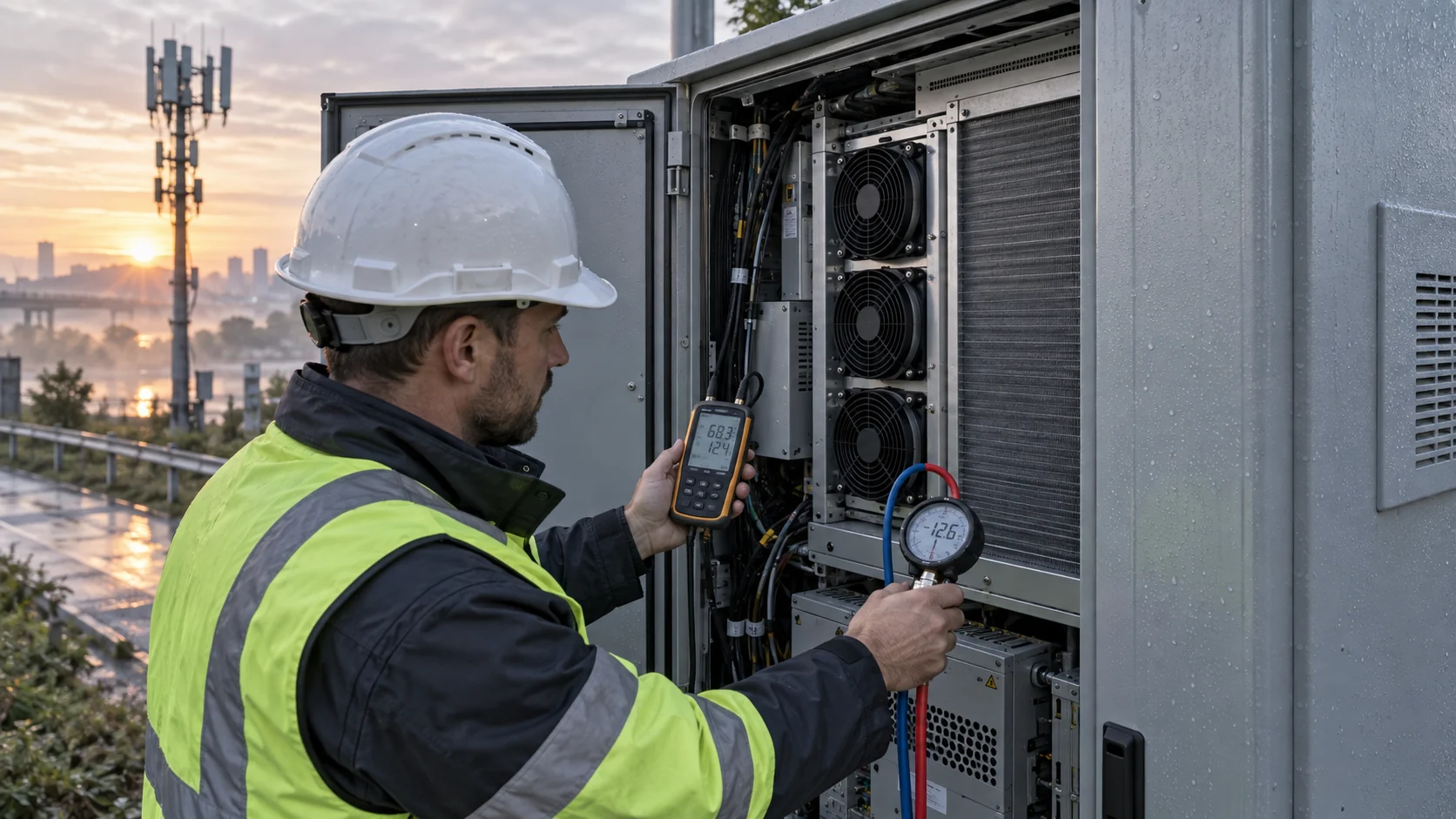
Two Fans in a Telecom Cabinet Do Not Automatically Create N+1 Cooling
A standby fan can protect a 5G cabinet only if the remaining fan can deliver useful airflow through the real filter, grille, heat exchanger and the stopped fan's reverse path.
Outdoor telecom cabinets combine continuous electronics heat with difficult surroundings: solar gain, high ambient temperature, dust, rain, salt mist, condensation and limited maintenance access. A 48 V fan may be electrically convenient, but voltage compatibility alone does not prove the thermal design.
The common redundancy assumption is simple: install two fans, run one, and expect the other to take over. In practice, the idle fan can behave as a restriction or windmilling load. The cabinet may also have a filter that has already accumulated dust, a louver that is partly blocked, or a heat exchanger whose pressure drop changes with airflow. N+1 must therefore be tested at the installed working point.
This guide focuses on the air-side and fan-side engineering questions. It does not define a telecom operator's network availability target, enclosure certification or site safety procedure.
The Engineering Hook: A Stopped Fan Is Part of the System Curve
When one fan stops, the remaining fan does not see the same air path it saw during the two-fan test.
A stopped axial fan can allow reverse flow through its blades, resist that flow, or interact with a backdraft shutter or grille. The result depends on the fan geometry, spacing, guard, pressure difference and electrical state. A stopped fan that is still connected to a controller may also produce a different mechanical condition from a fan that is electrically isolated.
For an illustrative estimate, suppose the cabinet needs 100 CFM at 120 Pa with both fans available. If the inactive fan and its branch add 35 Pa at the same branch flow, the surviving fan must deliver through the combined cabinet path rather than the clean single-fan curve. The exact airflow cannot be inferred by subtracting 35 Pa from a catalogue maximum; it must be measured or calculated from the fan and system curves.
Published outdoor fan-unit specifications show why the details matter: one documented 48 V assembly lists a defined airflow, pressure, voltage range, temperature range and single-fan cooling condition. Those values belong to that complete unit and should not be copied as universal telecom limits.
| Input | Why it matters | Evidence |
|---|---|---|
| Required airflow in N+1 | The surviving fan may see reverse-flow resistance | single-fan installed test |
| Filter maintenance state | Loading moves the operating point left | clean and final service pressure |
| Fan electrical isolation | A stopped motor may not behave like a free opening | wiring and controller state |
| Ambient and solar load | Cabinet heat margin falls at the site worst case | thermal profile and ambient record |
| Front service access | Replacement time affects the real availability state | maintenance procedure and clearance |
Do Not Use Maximum CFM to Prove Redundancy
The redundancy test belongs on the installed pressure-flow curve, with current, feedback and temperature recorded together.
Start with the cabinet heat balance. For a 600 W equipment loss and a planned 10 K air rise, the ideal flow from Qv = P/(rho x cp x deltaT) is about 0.05 m3/s, or 106 CFM, using air density about 1.2 kg/m3 and heat capacity about 1.0 kJ/(kg K). That is an ideal heat-balance estimate, not the fan requirement. Filter, exchanger, bypass, altitude and recirculation still determine the installed duty.
If the loaded filter adds 80 Pa, the heat exchanger adds 55 Pa and the grilles and bends add another 35 Pa, the air path already represents about 170 Pa before any uncertainty or reverse-flow penalty. If one fan is disabled and its branch adds a further 30 Pa to the surviving path, the N+1 test point is materially different from the normal two-fan test.
The measurement record should include airflow or a calibrated proxy, differential pressure across the defined path, fan voltage, current, PWM or EC command, FG/RD feedback, cabinet temperatures and the inactive fan's electrical state. A normal tach signal only proves rotor feedback; it does not prove that the hot electronics receive the required air.
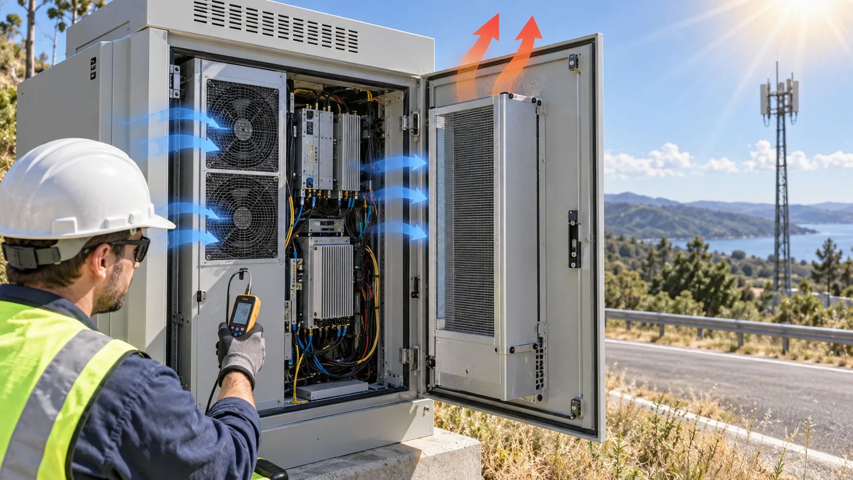
Interactive: Watch the Air Path Change After One Fan Stops
The animation separates normal two-fan operation from the N+1 condition and shows why the idle branch must be included in the test plan.
Use the animation as a review prompt, not as a CFD result. The actual cabinet may use an air-to-air heat exchanger, internal recirculation loop, filtered ventilation or a hybrid arrangement. In each architecture, define where the pressure is measured and what the surviving fan must cool.
A useful acceptance sequence is: both fans at the normal command, one fan electrically isolated, one fan stopped but still in its installed branch, loaded filter, high ambient and a return to normal operation after the replacement. Record the time to temperature recovery and whether the alarm or controller response is appropriate.

48 V Does Not Remove Startup and Control Questions
Telecom DC rails can be wide and dynamic; the fan must start and report correctly at the declared voltage limits and thermal state.
Define the actual rail range rather than writing only 48 V on the specification. A documented outdoor unit may operate across a range such as 36 to 60 V, but the fan, controller, connector, protection and alarm logic must be checked as an assembly. Undervoltage during a site event can be more important than nominal operation.
Validate PWM or voltage control, FG or tach pulse behavior, RD or locked-rotor indication, current during startup, restart after a thermal event and the behavior of a fan that is disconnected or blocked. Do not assume a replacement fan will have the same pulse count, active level or minimum start duty as the original.
For a small first build, MEGA Tech can match the frame, voltage, airflow direction, connector, feedback and control interface, then adjust the sample for the installed pressure, temperature, noise and service requirement. The comparison should include the actual operating envelope instead of a nominal part-number match.
Outdoor Life Is a Filter and Material Problem Too
The fan sees the field environment through the cabinet's air path, even when the enclosure specification looks clean on paper.
Dust, salt mist, humidity and condensation can change the filter pressure, impeller balance, bearing condition, connector reliability and PCB insulation. A fan with a suitable component rating still needs a cabinet-level maintenance plan. Filter media, gasket compression, rain hood, drain path and cable gland are all part of that plan.
Set the service state from evidence. Record the clean differential pressure and fan current, then define the approved final filter pressure or a trend-based service trigger. A calendar interval copied from another site can be wrong for a coastal cabinet, construction corridor or dusty roadside installation.
The service design should also state how the operator replaces the fan. If the front panel cannot be opened without exposing sensitive electronics or removing the entire rack, the theoretical redundancy may be lost during a real maintenance event.
- Measure clean and loaded-filter pressure at the same fan command.
- Inspect bypass gaps, gaskets and drain paths after service.
- Separate salt, dust, humidity and washdown requirements.
- Check bearing, impeller balance, connector and PCB protection for the duty.
- Validate fan replacement time and restart response at the cabinet front.
Build an Acceptance Matrix That Procurement Can Use
The final fan decision should be traceable from the thermal requirement to the sample evidence and the production interface.
A useful matrix lists the operating point in normal and N+1 conditions, the filter state, ambient condition, fan command, current, feedback, acoustic result, cabinet temperatures and recovery time. It also records what happens when the inactive fan is electrically isolated, mechanically stopped or removed from the branch, because those are not always equivalent conditions.
Separate measured values from estimates and vendor catalogue limits. A product page may state maximum airflow or static pressure, but the test report must state the measurement condition and show where the cabinet actually operates. This prevents a high free-air number from disguising a low N+1 flow.
If the surviving fan cannot keep the equipment within its approved limit at the service condition, the solution may be a higher-pressure fan, a lower-resistance filter, a backdraft path, a different heat exchanger or a revised redundancy architecture. The answer is not always more RPM.
Where MEGA Tech Fits In
We help telecom teams turn a 48 V fan requirement into an installed sample that can be tested at the cabinet boundary.
MEGA Tech can review custom DC axial fans, compact blowers and fan modules for 5G cabinets, roadside telecom enclosures, power cabinets and network equipment. The review can cover pressure-flow behavior, 48 V range, PWM or voltage control, FG/RD feedback, connector and cable exit, bearing configuration, temperature, dust and humidity exposure, vibration, noise and N+1 operation.
For a first review, provide the cabinet heat load, solar and ambient range, filter and heat-exchanger pressure data, airflow target at pressure, fan cutout and depth, voltage tolerance, feedback definition, service condition, redundancy logic, acoustic point and quantity. A populated cabinet or representative thermal mock-up is more useful than a fan part number alone.
We can also evaluate cost-competitive replacements for Sanyo Denki, SUNON, Delta, NMB or ebm-papst fans when the replacement is compared at the same installed working point and electrical interface. The sample should prove the thermal, electrical and service behavior that the telecom team actually needs.
Engineer FAQ: Outdoor Telecom Fan Redundancy
These questions keep N+1, filter service and 48 V fan selection tied to measurable evidence.
Q: Does two fans mean N+1 cooling? A: No. The surviving fan must meet the required airflow at the single-fan installed pressure, including the stopped branch, filter and heat exchanger.
Q: Is a 48 V fan automatically suitable for a telecom cabinet? A: No. Verify voltage range, startup, control, feedback, temperature, pressure-flow behavior, protection and service conditions.
Q: Should the inactive fan be removed during the N+1 test? A: Test the defined failure state. A stopped installed fan, an electrically isolated fan and a removed fan can create different air paths.
Q: Can the fan's maximum static pressure prove N+1 airflow? A: No. Use the fan curve and system curve intersection at the actual filter, grille, exchanger and cabinet condition.
Q: How should filter service limits be set? A: Record a clean baseline at a defined command, use the filter supplier's final pressure data and confirm the thermal response at the maintenance condition.
Q: Does an IP-rated fan make the cabinet IP-rated? A: No. The full enclosure, seals, filter, grille, cable entries and service covers require their own evaluation.
Q: What does MEGA Tech need for a replacement review? A: Current fan data, cabinet heat load, airflow and pressure target, filter/exchanger data, 48 V limits, PWM/FG/RD definition, dimensions, environment, redundancy state and acceptance plan.
Outdoor 5G Cabinet Fan Review Checklist
Use this list before freezing the fan, filter and redundancy architecture.
- What is the continuous and peak equipment heat load including solar gain?
- What airflow is required at the real loaded pressure, not free air?
- What happens to the surviving fan when the other fan is stopped in place?
- Are clean, loaded-filter, high-ambient and single-fan states all tested?
- What 48 V range, startup current, PWM, FG and RD behavior must be supported?
- Where are the pressure taps and temperature measurement points?
- How are dust, salt mist, humidity, condensation and rain handled?
- Can the front-service procedure replace a fan without losing the thermal state?
- What alarm, derating and recovery action follows fan failure or feedback loss?
- Which values are measured, which are estimates and which belong to the cabinet certification?