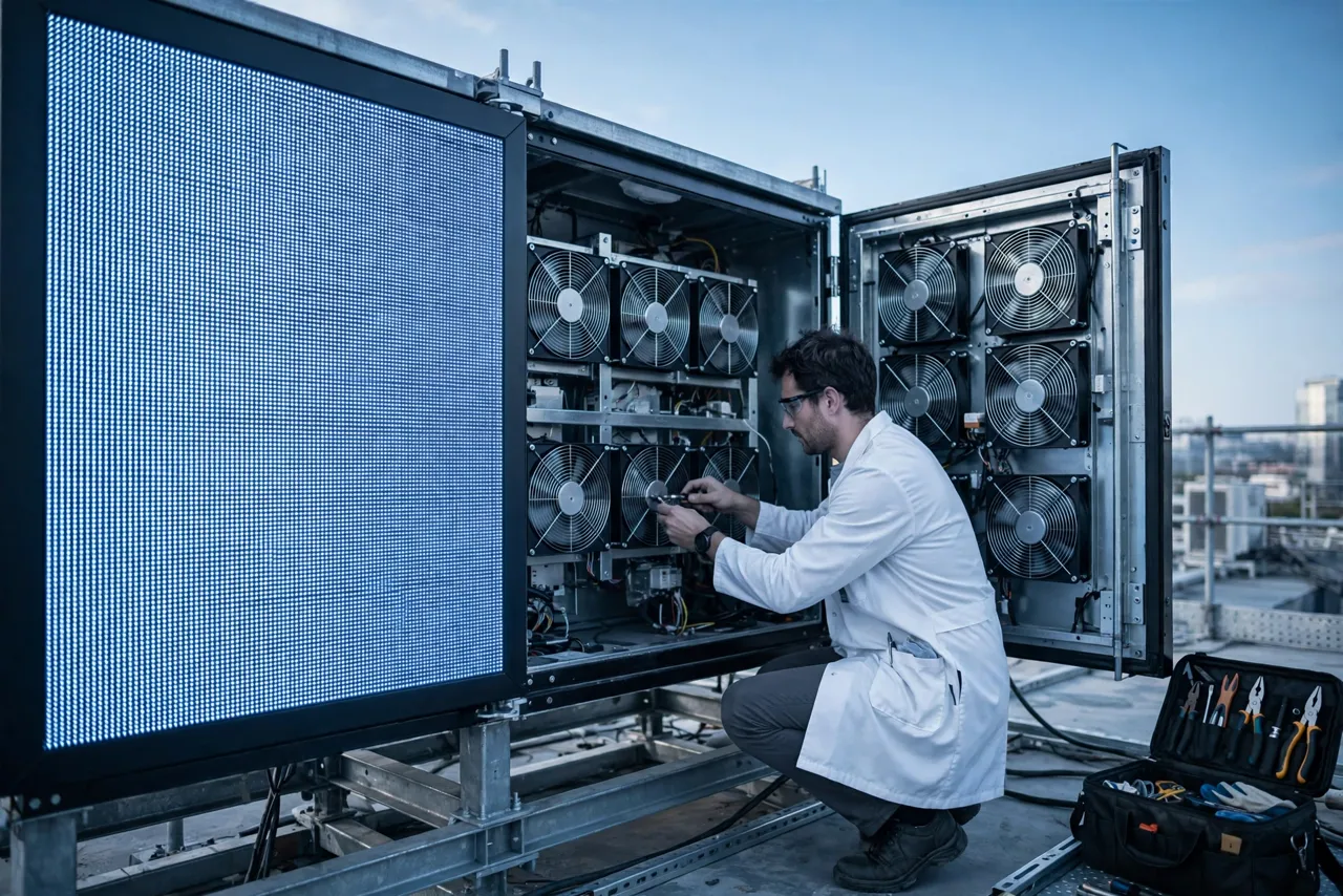
The screen dims before it dies
An outdoor LED display rarely fails with a bang. The first symptom of a thermal problem is on the wall for everyone to see: the screen is not as bright as the one sold across the street.
LED light output falls as junction temperature rises, and the accelerated-life testing behind LED ratings (the IES LM-80 measurement series and the TM-21 projection method built on it) is quoted at a defined junction temperature, not at whatever the cabinet happens to reach in July. Run the chips hotter than the rating assumption and two things happen at once: instantaneous brightness drops, and the lifetime projection stops meaning anything. Neither shows up on a monitoring dashboard as a fault.
That is why the thermal design of an outdoor display is a brightness decision, not only a reliability decision. The screen that derates on a summer afternoon looks identical to the one that was value-engineered at purchase; the difference is visible two years later, in a side-by-side photo at dusk.
The rest of this article turns the problem into numbers a fan can be specified against: where the heat comes from, what the sun adds, what a sealed IP65 cabinet does to the heat path, how much air actually solves it, and what the fan, the filter and the control loop each have to do for the screen to still meet its brightness specification in year five.
Where the watts come from
Two heat sources share one cabinet: the screen itself, and the sun. They add, and they peak within a few hours of each other.
Start with the screen. An LED converts roughly 20-30 percent of its input into light; the rest becomes heat in the package, and the driver ICs and power supplies add their own losses on top. For a typical outdoor full-colour panel, input power of 300-800 W per square metre is common depending on pitch and brightness class, with full-white peak content at the top of that range and ordinary video content well below it. On a 10 square metre screen, average electrical input on realistic content lands near 3 kW, of which roughly 70-80 percent - call it 2.2 kW - must leave as heat.
Then the sun. Clear-sky solar irradiance at ground level peaks near 1000 W per square metre on the exposed face. A dark cabinet front absorbs on the order of 80 percent of it, so a 10 square metre dark face takes in something close to 8 kW at solar noon - more than three times the electronics' own average load, deposited on the same structure that has to conduct the electronics' heat out.
The two loads are also phase-aligned. Irradiance peaks at solar noon; screen power peaks with viewing hours in the afternoon; ambient air temperature peaks one to three hours after noon. The worst case is not a spike but a plateau from early to mid afternoon, and the cooling system has to hold the brightness specification through all of it, every clear day, for years.
| Source | Magnitude | Notes |
|---|---|---|
| LED packages + driver ICs | About 70-80 % of screen input power | 2.2 kW at 300 W/m2 average content; 6-9 kW at full-white peak |
| Power supplies | Included above; 5-10 % of input each | Often the hottest component in the cabinet interior air |
| Solar gain, dark face | Up to about 8 kW absorbed at 1000 W/m2 | Depends on coating, orientation and shading; falls fast off-noon |
| Solar gain, light coating | About 2.5 kW at the same irradiance | Absorptivity around 0.25 versus around 0.8 for dark grey |
IP65 keeps water out and heat in
Sealing is the correct call for an asset that lives in rain, dust and salt air. It is also the reason the heat path is hard.
IP65 in the IEC 60529 code means dust-tight and protected against water jets - the de facto rating for outdoor displays, and for good reason. A ventilated cabinet on a roadside ingests dust, pollen and washing water; near the coast it ingests salt, which is conductive and corrodes; in agricultural or desert regions it ingests exactly the particulate that destroys boards and fans fastest. Every one of those enemies argues for the sealed cabinet.
But every gasket that keeps water out also keeps heat in. In a sealed display there is no through-flow of air: heat must travel from the LED junction through package, PCB, thermal pad and aluminium rear shell into the cabinet interior air, and then leave the cabinet entirely through its outer surfaces. Nothing inside the cabinet can be cooled below the inside air, and the inside air cannot be cooler than the surfaces that carry heat out.
This is why an IP65 rating says nothing about thermal adequacy. The rating proves the enclosure keeps water and dust out under the standard's test conditions; it is silent on whether the same enclosure can reject 5 kW on an unshaded wall at 40 C. The two properties are designed and proven separately, and the second one is where displays disappoint.
The heat path from junction to sky
One series resistance chain decides the junction temperature. Drawing it out shows exactly where a fan helps and where it cannot.
Follow one watt from an LED junction on a hot afternoon. It leaves the chip through the package and solder joint into the module PCB, crosses a thermal pad or gap filler into the aluminium rear shell, and from there into the cabinet interior air. Up to this point everything is conduction, and the fan has done nothing. The final steps belong to the air: inside, circulation fans keep the interior mixed so the shell sees moving air instead of a stagnant layer; outside, either natural convection or exhaust fans carry heat from the cabinet surfaces into the ambient.
A representative ladder for a working sealed design at 40 C ambient reads: junction about 85 C, package and solder pad near 80 C, module PCB around 72 C, thermal pad about 70 C, aluminium shell near 65 C, cabinet interior air at or below 55 C. Each step is a resistance in series, and the junction lands wherever the sum puts it. Two of those steps - interior air mixing and shell-to-ambient transfer - are the ones a fan controls.
The design consequence is a rule of priorities. Fix conduction first: pad material, contact pressure, shell thickness. Then spend fan budget on the two air-side resistances. A project that buys a larger fan to compensate for a dry or under-compressed thermal pad is paying for airflow that never reaches the junction.

Three cooling paths and where each one stops
Passive convection, filtered forced air, and air conditioning are not three grades of the same option. Each has a load range where it is the right answer.
Passive cooling relies on natural convection and radiation from the cabinet surfaces, usually helped by a 100-150 mm service gap behind the cabinets acting as a chimney. It has no fans, no filters, no noise and no fan power draw, and for screens up to roughly 300 watts of heat per square metre of cabinet it is often sufficient. Its ceiling is physics, not cost: still-air convection plus radiation gives a combined transfer coefficient in the region of 5-6 watts per square metre-kelvin, so every additional kilowatt needs another few square metres of surface or another few kelvin of rise.
Filtered forced air adds fans and a controlled path - intake low, exhaust high, through weather louvers and filter media - without giving up the weather rating, provided the inlet path is engineered rather than punched. It multiplies the shell-to-air transfer by an order of magnitude and mixes the interior so no pocket stagnates. Its price is a maintenance schedule: filters load, fans age, and both must be on the site's work list.
Air conditioning keeps the cabinet sealed and active: a compressor loop holds interior air below ambient regardless of load or sun. It is the answer for high-brightness screens in hot climates, fully enclosed facades, and any installation where the interior must stay below peak ambient. Its price is capital, energy, condensate management and its own maintenance - which is why a fan-based design that meets the target is usually the better engineering, not just the cheaper quote.
| Criterion | Passive convection | Forced air (filtered) | Air conditioning |
|---|---|---|---|
| Heat load where it fits | Up to roughly 300 W/m2 of cabinet | Roughly 300-800 W/m2 and above | Any load; chosen when interior must stay below ambient |
| Interior air vs ambient | Above ambient, load-dependent | 15-20 K above ambient at the design load | Below ambient, setpoint-controlled |
| Weather integrity | Sealed, no penetrations | Sealed path via louvers + filter, engineered inlet | Fully sealed, active loop |
| Maintenance burden | Surface cleaning only | Filter service, fan replacement | Compressor service, condensate, filters |
| Typical failure mode | Slow brightness loss in heat waves | Loaded filter moving the operating point | AC outage becomes a thermal emergency |
Sizing the air: the calculation that ends the argument
Fan arguments end when the required volume flow is written down. The formula is short; the discipline is in the inputs.
For a forced-air cabinet, the delivered volume flow obeys q = P / (rho x cp x dT), where P is the heat the air must carry, rho the air density, cp the specific heat of air, and dT the allowed temperature rise from inlet to outlet. With rho about 1.1 kg/m3 at hot-cabinet temperatures and cp about 1005 J/(kg x K), a 15 K rise carries roughly 16.6 watts per litre per second of flow.
Apply it to the 10 square metre screen. Average content puts 2.2 kW into the interior air; at a 15 K rise that needs about 480 m3/h of delivered flow. Full-white peak content pushes the electronics load to 6 kW or more, and holding the same 15 K at that load needs on the order of 1300 m3/h. Whether the fans must cover the peak continuously is a content decision - but the cabinet must survive it, so the design point and the duty split between the two numbers have to be written down, not assumed.
Three corrections come before a fan model number. Filter loading: size the duty at the dirty-filter pressure drop, not the clean one, because the fan rides its own curve and flow falls as resistance rises. Installed resistance: louvers, meshes and internal baffles all move the operating point away from the free-air rating on the box. Density: hot sites at altitude carry proportionally less mass per cubic metre, and the same kilowatts need proportionally more cubic metres.
Sun, orientation and coating: the load you can delete
The electronics load is fixed by the content. The solar load is a design choice, and it is the larger of the two.
Solar absorptivity spans roughly 0.25 for a light coating to around 0.8 for dark grey, so the same face can take in a third of the heat depending on finish alone. Orientation multiplies the difference: a south-facing vertical wall in the northern hemisphere takes the full noon load, an east-west face splits it into morning and afternoon peaks, and a light-coloured or ventilated sunshield with an air gap in front of the cabinet removes most of what remains.
The standard test behind such exposure is IEC 60068-2-5, Test Sa: simulated solar radiation at ground level, with an irradiance of 1120 W/m2 within 10 percent. Procedure A - 8 hours of irradiation and 16 hours of darkness per 24-hour cycle, for a daily dose near 8.96 kWh/m2 - exists specifically to assess thermal effects, and cycling it is a fair laboratory stand-in for the worst clear day. Asking a cabinet vendor for Test Sa data on the exact finish and geometry is a legitimate, cheap screening step before any fan is specified.
The arithmetic of deleting solar load is blunt. On the reference 10 square metre screen, moving the front from dark grey to a light finish cuts absorbed solar from near 8 kW to about 2.5 kW; adding a shaded, ventilated air gap in front of a dark face removes most of the rest. Compared with the airflow needed to carry the same kilowatts out, that is the cheapest cooling capacity in the whole project.
Filters, salt and insects: what IP65 does not cover at the fan inlet
A filtered forced-air design is only as sealed as its weakest inlet detail, and only as durable as its service schedule.
IP65 applies to the enclosure as built. A forced-air variant keeps the rating through engineered details: weather louvers that throw water off the intake path, filter media behind them, and mesh fine enough to stop insects - which in many regions are the number-one cause of clogged intakes, ahead of dust itself. Each layer adds pressure drop, and the sum at the dirty condition is what the fan must be selected against.
Salt air attacks everything the path exposes: mesh, blade surfaces, bearings, fasteners. Coastal and industrial installations need fan materials and coatings selected for it, sealed bearings, and a washing-friendly layout - the same arguments as any outdoor cabinet, but with one difference: a display is a visible, contractual object, and a streak of rust down a cabinet front is a customer complaint before it is a maintenance item.
None of this survives on goodwill. Filter service intervals belong in the site's preventive work list from day one - monthly or better in dusty and agricultural regions, and driven by a differential-pressure alarm rather than a calendar wherever the budget allows. A design that cannot say who changes the filter is a passive design that has not admitted it yet.
Night: the corrosive half of the duty
The display switches off, the sun goes down, and the cabinet begins to breathe in humid air. What condenses overnight shows up as failures in year three.
A cabinet that runs 40-60 K above ambient all afternoon cools after sunset, and the air inside contracts, pulling in night air through every path available - including, in humid coastal climates, air close to its dew point. Moisture films on the coldest metal first: terminal blocks, PCB corners, the inside of the front mask. The damage is cumulative and invisible: corrosion, tracking on insulation surfaces, electrochemical migration on populated boards.
Fan strategy is part of the defence. A low night circulation speed, or intermittent runs, keeps interior air mixed and the coldest surfaces slightly above what still air would give them; paired with a heater and a humidity or dew-point input it is the standard anti-condensation approach for sealed cabinets. Designs that cycle daily through a wide temperature range also benefit from a pressure-equalisation membrane vent, which lets air pass without letting liquid water or dust in.
Two cautions apply. A fan running at a few percent of speed can stall without its feedback signal looking wrong, so the low-duty corner has to be tested explicitly, with rotation detection that reads zero when rotation stops. And night operation must respect the site's acoustic limit - for displays near housing, the quietest hours are exactly when the sound of a failing bearing carries farthest.
Control: fan speed, brightness and the 55 C line
A display is one of the few products whose thermal control is visible to the customer. The control law deserves the same engineering as the fan.
The standard architecture is a sensor ladder with two actuators. Cabinet air sensors drive fan speed in stages; a brightness derating curve guards the LED junction when the air-side runs out of headroom. Done well, the fan holds the interior at or below its design limit across the whole day, the derating curve is never touched in normal operation, and the audience never sees either one working.
The day the curves describe makes the requirements concrete. Ambient climbs from the mid-20s at dawn to 40 C mid-afternoon; a passive cabinet tracks tens of degrees higher and crosses any reasonable brightness threshold by mid-morning; filtered forced air holds a 15 K rise and stays near 55 C through the peak; air conditioning holds a nearly flat line a few degrees above its setpoint. The fan system has to deliver its curve at the worst hour of the worst day - which is also when solar load, content load and filter age all align.
Instrumentation turns that from a hope into a contract. RPM feedback on every fan, cabinet air temperature at the exhaust, and a logged derating event counter give the operator a fleet view: which sites run hot, which filters load fast, which fan batch ages early. For a product sold on brightness, the derating counter is the closest thing to a customer-satisfaction meter the cabinet has.

Maintenance and monitoring: keeping the design true
Every number in this article assumes a filter that breathes and a fan that spins. The maintenance schedule is part of the thermal design.
Filter service is the first-order item. In dusty, agricultural or pollen-heavy regions a filter can load substantially within weeks of one event, and a loaded filter moves the fan's operating point left: less flow, more noise, higher cabinet temperature, with no electrical fault to alarm on. Pressure-differential sensing across the filter converts this into a signal; a calendar schedule alone guarantees service is either early or late.
Fan replacement is a scheduled event, not a surprise. Duty hours on a display are long - a 16-hour-per-day screen accrues nearly 6000 hours a year - and bearing life falls steeply with temperature. Industry practice on outdoor displays treats two to three years as a normal service window for fans in hot cabinets; the honest number comes from the fan's own life data at the actual cabinet temperature, not from a generic curve. Front-serviceable fan trays that swap without opening the sealed chamber, with the spare defined in the BOM, turn the event into a short stop.
Monitoring closes the loop between design and operations. Trending RPM, current and temperature separates a loaded filter (speed up, flow down, delta-P up) from an ageing fan (current up, RPM drifting, acoustics changing) from a blocked exhaust. The trending costs almost nothing to log and is the difference between replacing parts on evidence and replacing screens on complaint.
| Item | Typical interval | Signal that it is overdue |
|---|---|---|
| Filter service / replacement | 1-2 months in dusty regions; pressure-driven where instrumented | Delta-P alarm; fan RPM rising at constant PWM |
| Fan inspection / replacement | 2-3 year service window in hot cabinets | Current or acoustic drift; RPM below command |
| Inlet mesh and louver cleaning | Monthly in insect season | Visible loading; intake depression rising |
| Cabinet surface cleaning | Quarterly to semi-annual | Visible film; shell temperature rising at same load |
What MEGA Tech can do here - and what we need from you
We build cooling fans for exactly this duty: specified around the site conditions, and proven on the customer's own cabinet before the BOM is frozen.
What we do is selection and customization around a real duty cycle. Frame size, thickness, voltage, speed curve, PWM control, FG/RD feedback, connector, cable length, bearing and lubrication choice, and protective measures for dust, salt or insect-laden air are all adjustable. Where an existing unit is being replaced - including machines built by Sanyo Denki (SAN ACE), SUNON, Delta, NMB or ebm-papst - we work from the installed duty and measurements rather than from the frame size alone, because equal outlines do not guarantee equal delivery on a given system curve.
What we need from you is the duty, not just the part number: screen size, pitch and brightness class; the content profile and the split between average and peak electrical input; cabinet construction, coating and orientation; the interior air limit and the brightness derating threshold; site climate, sun exposure, altitude and pollution; the louver, filter and mesh geometry; the acoustic limit by day and night; the target service life and replacement strategy; and any measured system curve or thermal data from the existing build.
Where we stop is also part of the answer. We do not supply the LED modules, the enclosure structure, the air-conditioning plant or the control electronics: IP rating, structural and electrical safety, and the brightness derating law belong to the display manufacturer. Our scope is the air side - interior mixing and shell-to-ambient transfer - and the evidence that it holds the specification in your cabinet.
- Fan selection against the installed system curve at worst-case ambient, solar load and dirty-filter conditions.
- Customization: frame, thickness, voltage, speed curve, PWM, FG/RD, connector, cable, bearing and lubrication, coating for dust or salt.
- Night-duty and anti-condensation variants validated at the low-speed corner, with rotation detection that reads zero on stall.
- Sample build, instrumented test and a documented working point before production release.
Recommended Fan Starting Points
These catalogue series may be suitable starting points for this application. Final selection depends on the installed airflow, static pressure, voltage, noise target and operating environment.
Request a sample for validation on your equipment.
Engineer FAQ: Outdoor LED Display Cooling
Short answers to the questions that come up when a screen is already on the wall and the afternoon is already hot.
Q: Is a higher-RPM fan the fix for a screen that dims every afternoon? A: Only if the installed path can use the extra flow. Check the system curve first: with a loaded filter, a tight louver or a blocked exhaust, more speed mostly buys noise and a worse operating point.
Q: How much airflow does a 10 m2 outdoor screen need? A: From q = P / (rho x cp x dT). At 2.2 kW of average electronics load and a 15 K rise, about 480 m3/h delivered; at full-white peak load, on the order of 1300 m3/h. Then correct for dirty-filter resistance and site density before selecting the fan.
Q: Can we just seal the cabinet harder and skip the filter? A: Sealing harder does not delete the heat; it moves the whole load onto conduction and surface transfer. If the load is above what passive transfer carries, you are choosing between filtered forced air and air conditioning, not between sealed and unsealed.
Q: Does painting the cabinet white really help? A: Yes, and it is free at design time. Absorptivity around 0.25 versus around 0.8 for dark grey cuts absorbed solar load on a 10 m2 face from roughly 8 kW to about 2.5 kW at the same irradiance - cooling capacity no fan has to carry.
Q: The screen is fine all day and fails at night. Is that the fan? A: Probably not directly. Post-sunset failures are usually condensation: a hot humid cabinet cooling through the dew point. Check the night strategy - low-speed circulation, heater, pressure-equalisation vent - before blaming the daytime cooling.
Q: How often should display fans be replaced? A: Treat two to three years as a normal service window in hot cabinets running long daily hours, and derive the real number from the fan's life data at the measured cabinet temperature. Define the spare in the BOM and make the tray front-swappable.
Q: What can MEGA Tech customize for this duty? A: Frame, thickness, voltage, speed curve, PWM, FG/RD, connector, cable, bearing and lubrication, and coatings for dust or salt - selected against your measured duty and validated on your cabinet.
Questions for the Display Cooling Design Review
A short checklist that keeps a brightness complaint from turning into an endless fan swap.
- What interior air temperature must hold at the worst hour of the worst day, and is the brightness derating threshold stated next to it?
- What is the electronics heat budget in watts, split between average content and full-white peak, and who owns it?
- What solar load does the front face take - coating, orientation, shading - and has any of it been deleted before sizing fans?
- Is the architecture passive, filtered forced air, or air conditioned - and is that choice driven by the load or inherited from a datasheet?
- What is the delivered airflow at the installed system curve at the dirty-filter condition, not the clean one?
- What is the allowed inlet-to-outlet air temperature rise, and does the resulting interior temperature protect the power supplies' life model?
- What happens after sunset: dew-point crossing, night circulation, heater, pressure-equalisation path?
- How is fan health reported - RPM, current, filter delta-P, derating events - and who reads the trend?
- Can fans be replaced from the front without opening the sealed chamber, and is the spare defined in the BOM?
- Has the candidate fan been measured on the actual cabinet across a real summer day, or only on a bench curve?