One Healthy Signal Does Not Prove a Healthy Cooling Path
A normal RPM reading is useful evidence of rotation, but it cannot show whether air crosses the intended filter, coil and equipment path.
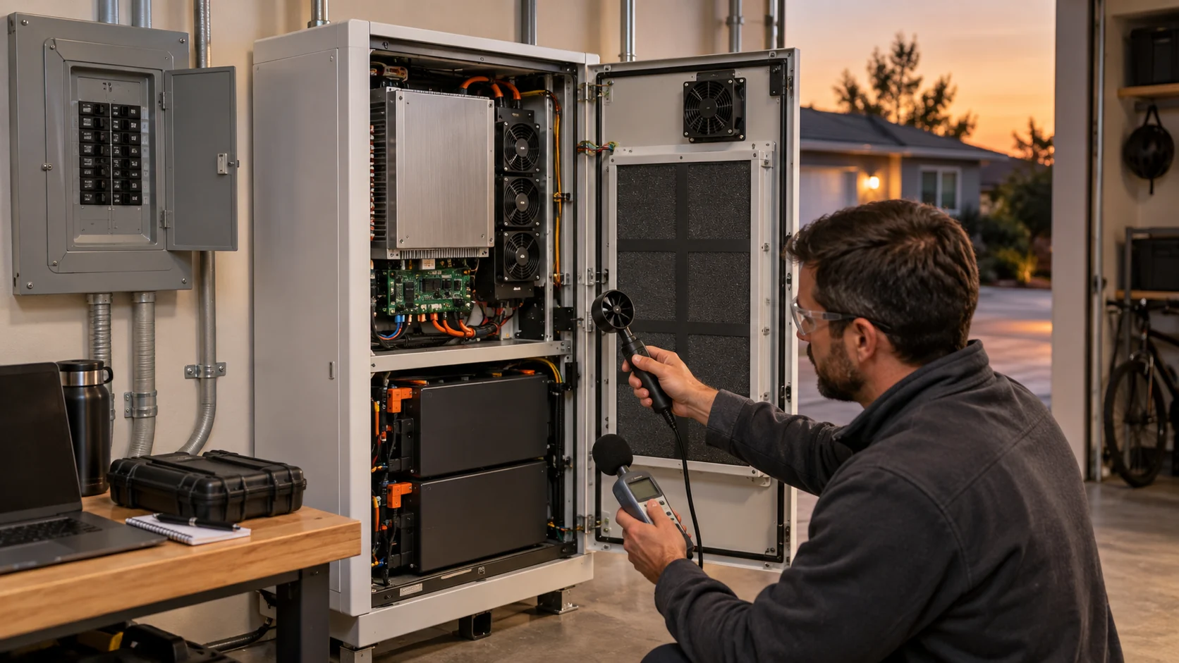
A battery enclosure fan can report perfect speed feedback while the battery module behind a loaded filter overheats. It can draw a normal current while a stuck louver has cut the airflow in half. No single electrical or mechanical signal isolates the fault. What works in the field is a matched operating record: the same fields, captured at comparable load and ambient, and read side by side.
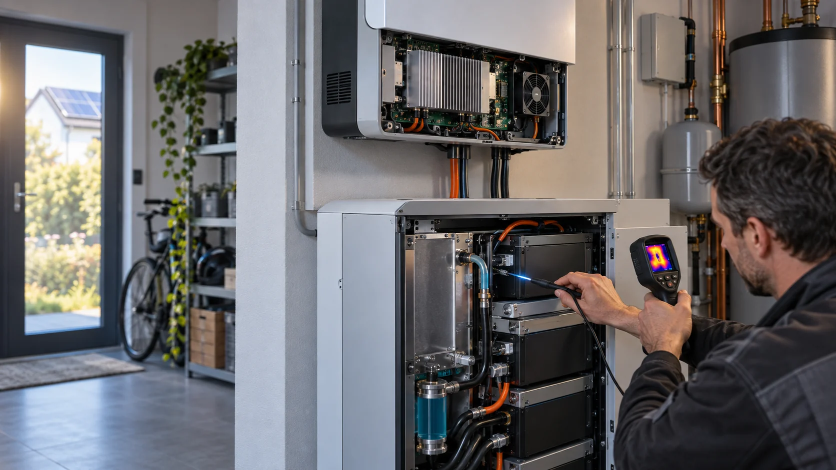
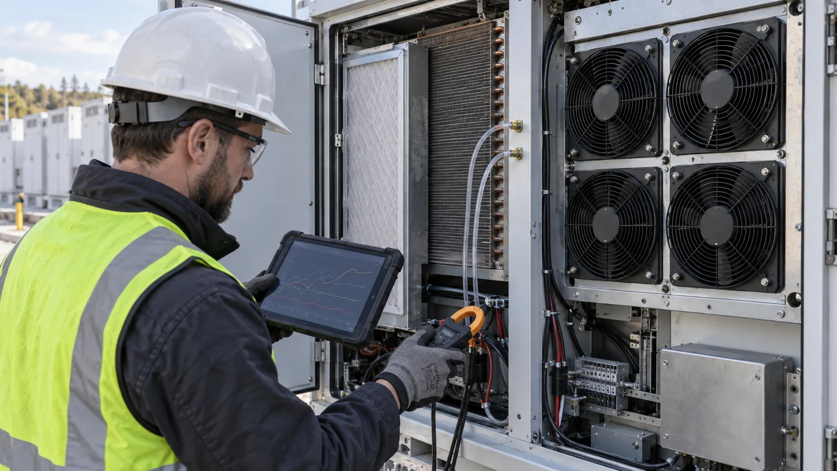
The record worth keeping is specific. Load current of the equipment being cooled, local intake air temperature, panel and louver state, filter condition, PWM command, FG or tach feedback, supply voltage, motor current, named pressure taps across the filter and coil, and fixed temperature points at the module. Comparing the same fields at a comparable duty point is far more useful than interpreting a single alarm after it has been cleared and lost.
This article is about normal-cooling maintenance, not battery safety diagnosis. A fan fault, a thermal runaway response and an emergency ventilation demand are separate engineering problems with separate requirements. The goal here is narrower: catch the fan, the filter and the air path while they are still cheap to fix, and know which signal earned you that conclusion.

The Five Signals and What Each One Can Rule Out
Command, speed, current, pressure and temperature each answer a different question. The table is the diagnostic method in one place.
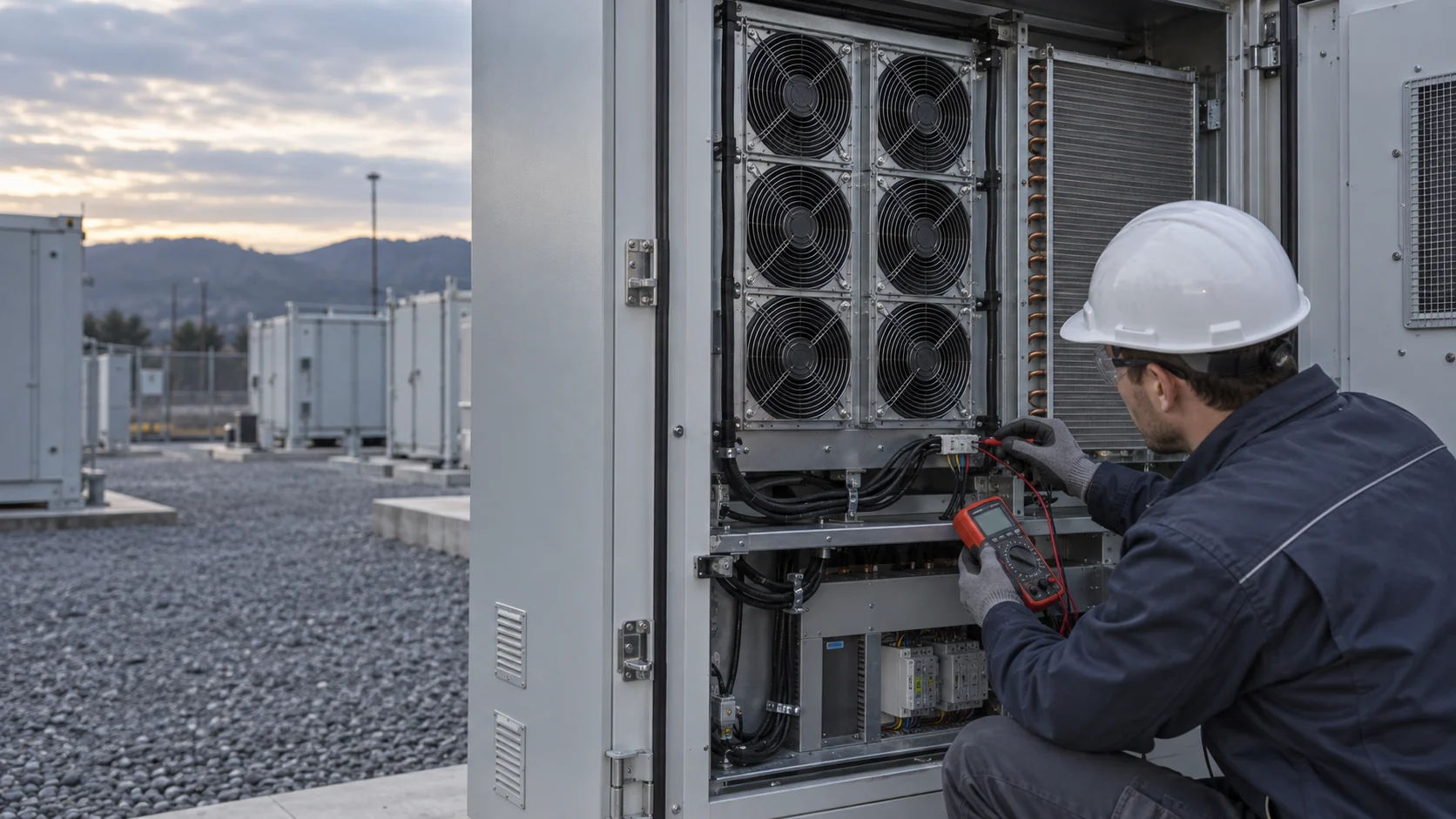
Four of the five signals are already available in most battery enclosures. PWM command is what the controller asks for. FG, the tachometer output on a three- or four-wire fan, usually emits two pulses per revolution, so the controller can count speed without extra hardware. Supply voltage and motor current come from the fan power rail. The fifth signal, differential pressure across the filter or coil, needs two pressure ports and a transducer, and it is the one most often left out. It is also the one that separates a fan problem from an air-path problem fastest.
Every DC fan datasheet states a speed tolerance, commonly plus or minus 10 percent, and FG pulse definitions. Commission against the actual delivered fan, not the catalogue typical, and record the baseline while everything is new. A warning threshold is only meaningful relative to a recorded commissioning value at a known duty point.
| Signal | Source | It can confirm | It cannot confirm |
|---|---|---|---|
| PWM command | Controller output | What the fan was asked to do | That the fan obeyed |
| FG / tach speed | Fan output, typically 2 pulses per revolution | That the rotor spins at the commanded speed | That the moved air reaches the module |
| Supply voltage and current | Fan power rail | Electrical load and driver health | Mechanical blockage vs electrical load |
| Differential pressure | Ports across filter or coil | The restriction the fan is working against | Which element loaded, without a second tap |
| Module temperature rise | Fixed sensors at the module | The thermal result of the whole path | Which part of the path caused it |
Read RPM Against the Command, Not Against the Nameplate
Speed feedback only means something next to the command, the supply voltage and the recorded baseline at the same duty point.
At a fixed PWM command and a stable supply voltage, a healthy fan holds its speed within a narrow band. Speed naturally varies with supply voltage, air density and manufacturing tolerance, which is why the datasheet tolerance is plus or minus 10 percent and why a single reading never decides anything. What decides is a sustained departure from the unit's own commissioning record: the same command, the same voltage, the same season, a lower speed.
As filters load, the fan works against higher back pressure. Depending on how the controller closes the loop, the result appears either as speed droop at a fixed command or as rising current at a fixed speed. Both are the same story told by different signals, and both are early. A fan almost never drops from baseline to stall in one step; it drifts for weeks.
Set the limits from the datasheet and a sample of delivered units, then keep them simple: investigate any unit whose speed sits more than 10 percent below its commissioning value at the same command, and act on a sustained reading below 80 percent. Treat zero pulses as a fault within seconds, not minutes, because a stopped fan in a battery enclosure is a thermal event in progress, not a maintenance item.
Bearing and Grease Temperature Set the Replacement Clock
The L10 hour rating on the datasheet is a conditional promise. Intake temperature is the condition, and it moves the number by factors, not percentages.
L10 is the running time at which 10 percent of a fan population is expected to have failed from bearing wear-out at the stated temperature. Two properties of that number matter for maintenance planning. First, grease life falls by roughly a factor of two for every 10 to 15 kelvin above the rating temperature; SKF publishes the factor-of-two-per-15-kelvin rule for sealed, lubricated-for-life ball bearings. Second, the spread is wide: the first failures in a population arrive long before L10, at roughly a fifth of it.
Worked example: a fan with an L10 of 50,000 hours at 40 C, installed where the air reaches 55 C and running continuously, loses roughly 60 percent of its rated grease life, leaving about 20,000 hours, under three years. On a site with 500 fans of that type, the first bearing failures should be expected years before the fleet average says so. Replacement budgets built on the catalogue number alone will be late.
Speed changes the clock too. Bearing fatigue life rises roughly with the ratio of rated to actual speed raised to the power 1.5, which is why a fan held at 70 percent speed can last 1.5 to 1.7 times longer than the same fan at full speed. Night setback schedules, covered in the noise article, quietly buy bearing life as well as quiet.
One more clock runs beside the bearing: the electrolytic capacitors inside an EC or DC fan driver age on a similar Arrhenius pattern, halving roughly every 10 kelvin. A fan can be mechanically perfect and electrically dead, so an over-temperature fault output from the driver is a maintenance signal in its own right.
Dust, Imbalance and the Vibration Signature
A fan about to fail vibrates differently long before it fails audibly, and the pattern in the spectrum names the failing part.
Dust does two separate kinds of damage. Deposited evenly, it loads the filter and moves the operating point. Deposited unevenly on the impeller, it unbalances the rotor, and unbalance shows up as a growing vibration peak at exactly one times the running speed. Misalignment and looseness concentrate at two times. Bearing race defects produce narrow peaks at the bearing pass frequencies. This is why a trend of overall vibration plus the running speed is diagnostic, while a single broadband number is merely alarming.
Formal severity zones exist in ISO 20816-3 for industrial machines above 15 kW: for medium machines on rigid foundations, the zone boundaries sit near 1.4, 2.8 and 4.5 millimetres per second RMS. Most battery enclosure fans are far below 15 kW, so the standard does not strictly apply to them, and pretending otherwise invites wrong thresholds. The practical method for small fans is baseline trending: record vibration on commissioning, alarm on a doubling from that unit's own baseline, and use the spectrum shape to decide whether the cause is balance, mounting or the bearing.
Vibration instrumentation on every small fan is rarely economic. That is fine. Dust unbalance also announces itself through signals the enclosure already has: a slow speed droop at fixed command, a rising current, and audible noise that changes with speed. Sample a few suspect units with a handheld meter, compare against fleet siblings, and you get most of the value of permanent sensors at a fraction of the cost.
Filter Differential Pressure: Clean, Loaded, Final
Differential pressure is the only signal that watches the air path itself, and it comes with published end-of-service numbers.
The working rule from ISO 16890 practice, as restated in air-handling-unit manufacturer manuals, is that a particle filter is due for replacement when its loaded pressure drop reaches either its clean value plus 100 pascals or three times its clean value, whichever is lower; coarse filters use 50 pascals or three times. AHU practice also publishes flat limits by class, in the region of 150 pascals for coarse classes and 200 to 300 pascals for fine classes. The exact number matters less than the discipline: define the replacement pressure drop at commissioning, wire the transducer to the controller, and alarm on approach rather than arrival.
Filter loading moves the other four signals in predictable directions. At a fixed PWM command, speed droops as back pressure rises. At a fixed speed target, current rises. The module temperature rise grows last, because thermal mass delays it, which is exactly why it is the worst early-warning signal and the best confirmation signal. A filter alarm that fires on schedule protects the bearing as much as the battery: the fan spends its life further out on its curve, at higher load, for every extra pascal the filter keeps.
Record the clean differential pressure of every enclosure at commissioning, with the fan at a stated command. Without that number, the loaded reading three years later has nothing to be compared against, and the pressure signal degenerates into decoration.
| Filter class | Published replacement limit |
|---|---|
| ISO coarse (G classes) | Clean value + 50 Pa, or 3x clean value, whichever is lower; flat limit about 150 Pa |
| ISO ePM10 / ePM2.5 (M5-F7 region) | Clean value + 100 Pa, or 3x clean value, whichever is lower; flat limit about 200 Pa |
| ISO ePM1 (F8-F9 region) | Clean value + 100 Pa, or 3x clean value, whichever is lower; flat limit about 300 Pa |
Three Worked Patterns: Read the Signals Together
Combinations, not single alarms, name the fault. These three cover most of what a BESS fan fleet presents.
Pattern one: speed low, current high, filter pressure high. The fan is fighting a restriction. Check the filter first, then the impeller deposits, then the louver. Replacement of the filter usually restores all three signals within minutes, and the incident becomes a line in the log instead of a module failure.
Pattern two: zero speed, alarm output active, command present. A locked rotor or a lost feedback line. The controller should already have escalated: raise the remaining fans, shed load, and open a service ticket with a time stamp. If the enclosure has an N-plus-1 array, this is the moment the redundancy validation, done at commissioning, pays for itself.
Pattern three: every fan signal healthy, module temperature rise growing anyway. The fans are telling the truth; the air is not reaching the module. Recirculation inside the enclosure, a bypass path, a failed louver blade or a shifted baffle all produce this signature. This is the pattern that punishes teams who treat fan telemetry as a thermal management system. The fan is a component; the temperature is the result.
Fleet Math: One Failed Fan Predicts the Next
Bearing wear-out is a population property. The first failure on a site is a forecast, not an accident.
Fan populations do not fail on schedule, and they do not fail randomly either. Random electronics failures arrive at roughly one percent per year for a fan with a one-million-hour MTBF; bearing wear-out arrives as a wave whose leading edge starts near one fifth of the L10 hours and whose tenth percentile is L10 itself. For a 500-fan site with an effective life of 20,000 hours, the realistic planning window for the first replacement batches is about four to five years, with the failure rate climbing after that.
The operational consequence is simple: track installation dates and serial numbers per enclosure, from the day of commissioning. When the first bearing failure lands, sort the fleet by age and duty hours, sample the oldest decile, and batch-replace ahead of the wave. Reactive, one-at-a-time replacement costs more truck rolls, and worse, it leaves mixed vintages in one enclosure, where an old draggy fan sits next to a new one and skews the airflow share.
Replacement is also a validation event, not a swap. The substitute fan must be checked against the enclosure at the same command points as the original: speed, current, filter pressure and module temperature rise. A part that spins but moves less air, or announces itself with a different noise floor, will be discovered by the module temperature days or weeks later unless the four signals are re-baselined on the spot.
Warning and Action Thresholds Worth Commissioning
A threshold nobody defined at commissioning becomes an argument during the fault. Write them down, per signal, before the site energizes.
The values below are starting points for a site-specific table, not universal limits. Every row should be adjusted against the datasheet of the installed fan and the recorded commissioning baseline, then frozen in the maintenance contract so that field crews and control engineers share the same numbers.
| Signal | Record | Investigate when | Act now when |
|---|---|---|---|
| FG speed at fixed command | Every duty cycle, trend weekly | Over 10% below commissioning baseline | Sustained under 80% of expected, or zero pulses |
| Motor current at fixed speed target | Every duty cycle | Over 10-15% above baseline | Any over-current alarm from the driver |
| Filter differential pressure | Continuous | Halfway to the defined replacement value | At the defined final value, or on alarm rate-of-rise |
| Bearing or shell temperature | Trend daily | 15 K above the unit baseline | Driver over-temperature alarm output active |
| Module air temperature rise | Continuous | 2 K above the commissioning delta at same load | Approaching any cell or module limit |
| Vibration (sampled) | Quarterly route | Double the unit's own baseline | Zone-style severity breach plus 1x peak growth |
Where MEGA Tech Fits In
Most of this article is about signals the enclosure reads from the fan. We build the fan half of that interface, and we hold it to numbers.
What we can do: supply custom DC and EC axial fans and backward-curved centrifugal fans with the monitoring interface built in rather than bolted on, including FG tachometer output with a stated pulses-per-revolution, standard 25 kHz PWM control, locked-rotor and over-temperature alarm outputs, and, where the site wants it, a stated L10 life with its temperature and speed assumptions printed next to the rating instead of buried in a catalogue footnote. We match the fan to the installed pressure, the altitude and the temperature profile of the site, not to a part number that looks similar, and we deliver samples that are validated in the customer's enclosure at the customer's duty points, with the five signals recorded alongside the customer's own telemetry.
What we need from the customer: the control frequency and logic level for PWM, the expected pulses per revolution and pull-up arrangement for FG, the polarity and sink capability expected of the alarm output, the site's ambient temperature and altitude profile, the connector and wire harness definition, the space envelope and mounting orientation, the noise target and where it is measured, and the maintenance interval the site actually plans to run. Those inputs decide whether the monitoring interface is useful or decorative.
Where our scope ends: we do not supply the battery management system, the vibration instrumentation, the filter media or the differential pressure transducers, and we do not write the analytics that turn trends into work orders. We can be held to what the fan reports and does at a stated operating point; the site-level alarm philosophy belongs to the enclosure designer, and it should, because the enclosure designer carries the consequence.
Engineer FAQ: BESS Fan Trend Monitoring
Questions that decide whether the telemetry is worth wiring at all.
Q: Does normal FG feedback prove airflow? A: No. It proves reported rotation; pair it with pressure and thermal evidence.
Q: What fraction of expected speed should trigger investigation? A: About 10 percent below the unit's own commissioning value at the same command and voltage; sustained operation under 80 percent deserves a ticket the same week.
Q: How fast must a zero-RPM event alarm? A: Within seconds. Two missed FG pulses in a row is already enough for a latched fault in most controller designs.
Q: Is vibration monitoring worth putting on every fan? A: Almost never on small fans. Baseline the fleet, sample suspects with a handheld meter, and alarm on a doubling from the unit's own baseline.
Q: Which signal fails first as a filter loads? A: Differential pressure. Speed and current follow within days to weeks; module temperature rise moves last because of thermal mass.
Q: Does running fans slower really extend life? A: Yes. Bearing life scales with roughly the 1.5 power of the speed ratio, so a fan held at 70 percent speed gains 50 to 70 percent bearing life, and the electronics run cooler too.
Q: What is the most common misreading of fan telemetry? A: Treating all-green fan signals as proof the thermal path is healthy. Recirculation, bypass and failed louvers pass every fan check while the module cooks.
Q: Can a replacement fan be validated without a lab? A: At the four commissioning points, yes: speed at command, current, filter pressure and temperature rise, recorded in the enclosure before the crew leaves.
Questions for a Design Review
Bring this list to the review; every unanswered question becomes a field surprise later.
- Which five signals does the controller record per fan, and where does the record live after the alarm clears?
- What is the commissioning baseline per unit, and who is contractually required to write it down?
- What speed deviation, in percent against baseline, opens a ticket, and what deviation forces one?
- Where are the pressure taps, and is the clean differential pressure of every enclosure on file?
- What L10 life is the fan purchased against, at what temperature and speed assumptions?
- What does the controller do on zero pulses, on over-temperature alarm, and on N-plus-1 loss: in what order, at what delays?
- How are replacement fans re-baselined, and who confirms the four commissioning points before the crew leaves?
- How is fleet age tracked, and what triggers the batch replacement wave before the leading edge arrives?