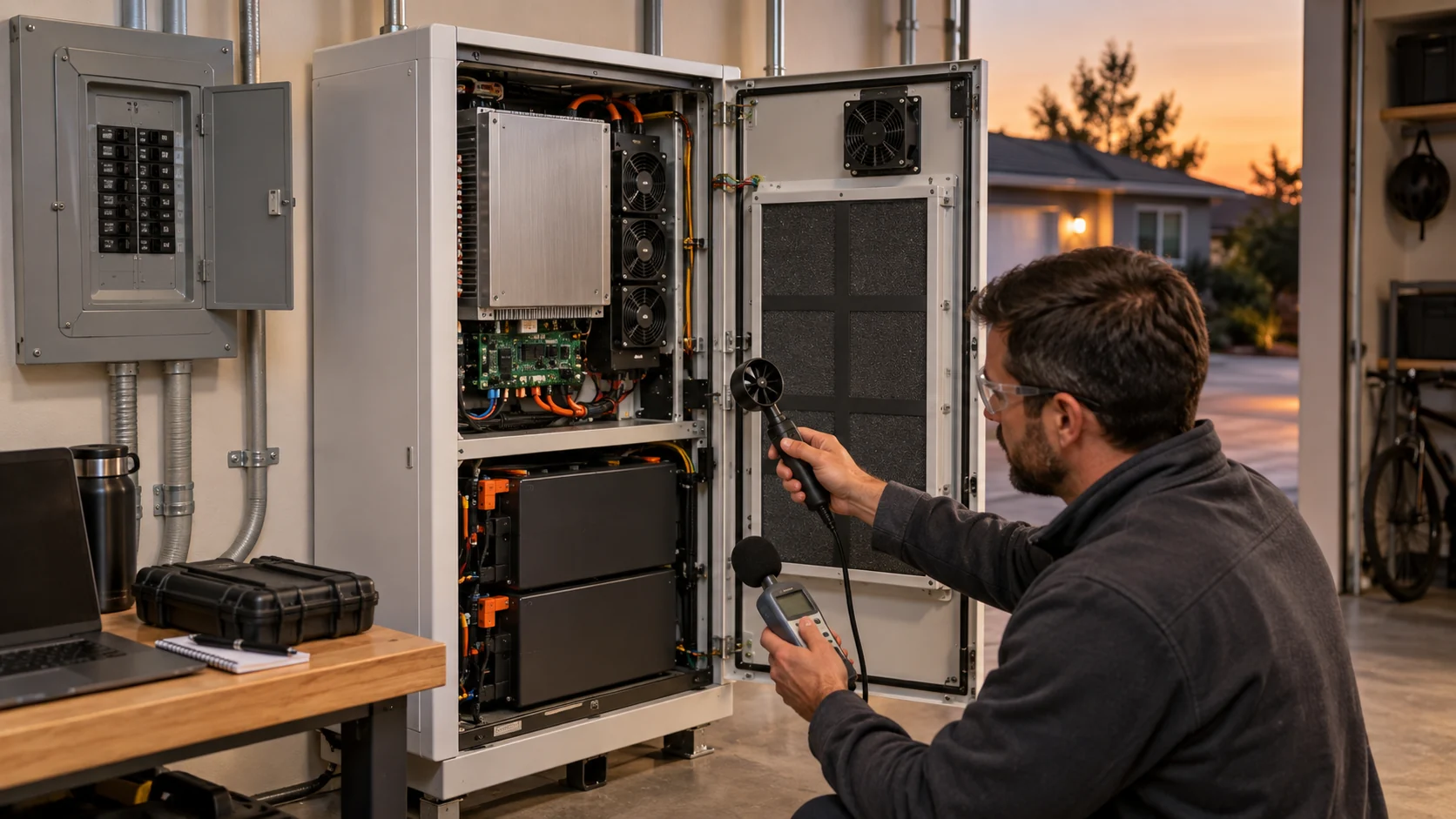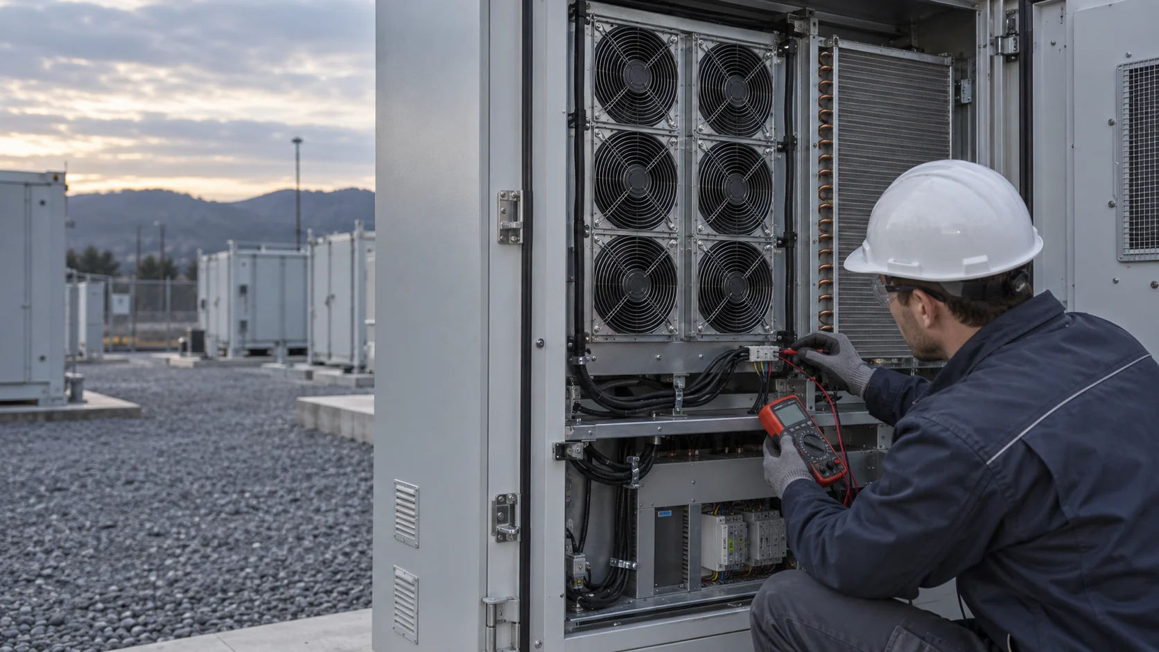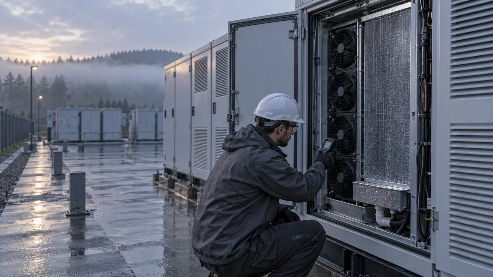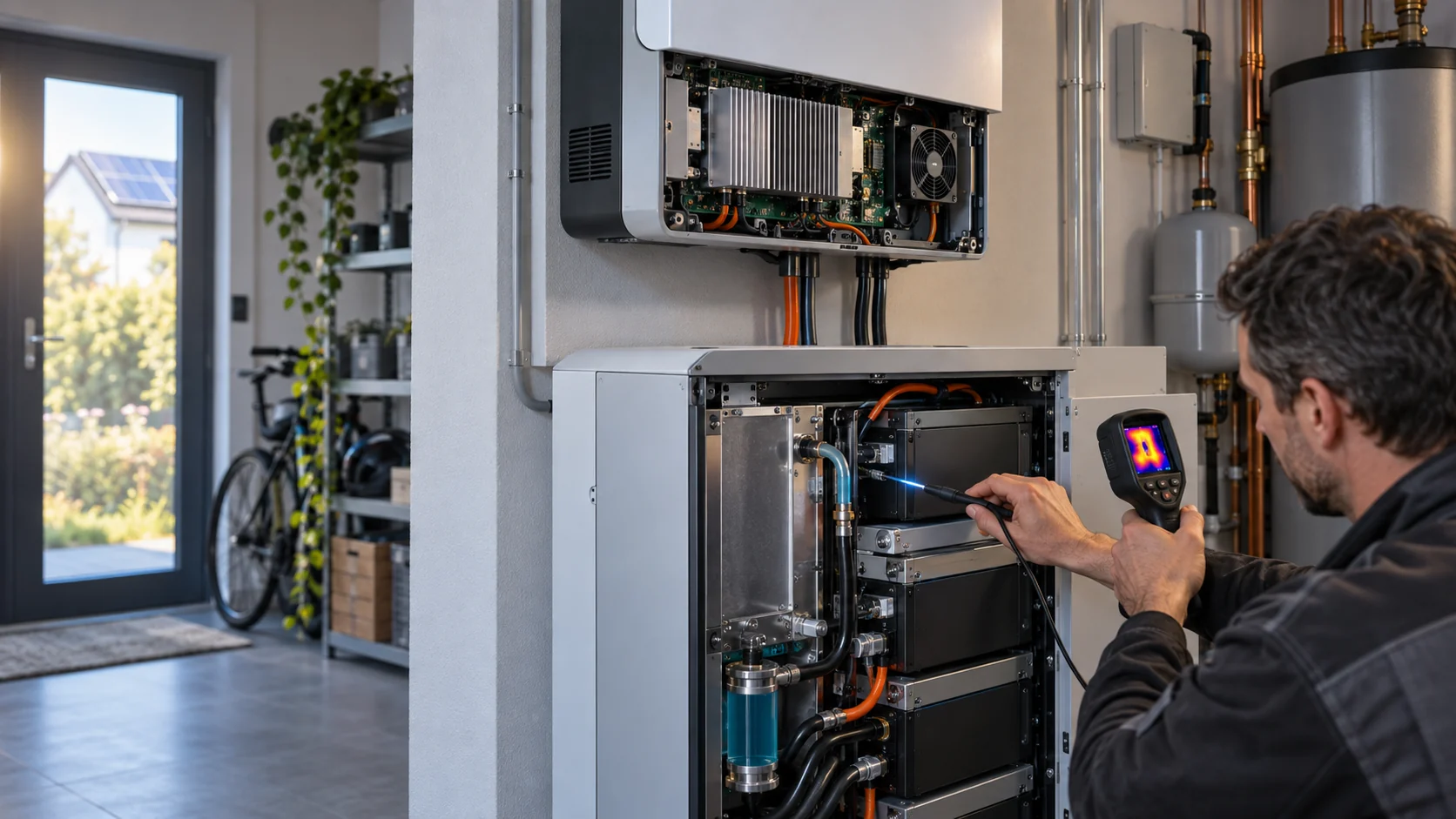
The First Question Is Not Which Fan to Buy
Residential solar-storage systems use different thermal architectures. A good design review starts by identifying the heat source and the required boundary, then deciding whether passive, liquid or fan-assisted cooling is appropriate.
A home energy storage product may combine a battery module, a hybrid inverter, MPPT electronics, contactors, communications and backup switching in one visual package. Those blocks do not generate heat in the same way. The battery may be designed for conduction or liquid thermal management while the inverter power stage still needs a defined air path. Conversely, a compact product may be naturally cooled and need no airflow fan at all.
That distinction matters commercially as well as technically. A fan supplier should not claim that every residential battery needs a fan. The useful question is narrower: if the product has an air-cooled inverter or electronics bay, can the installed path remove the heat quietly, reliably and with enough margin at the worst ambient condition?
This guide gives thermal, mechanical and procurement teams a practical selection method. It is written for European residential systems installed on an outside wall, in a garage or in a utility space, where high summer ambient, night-time noise, dust, moisture and limited enclosure depth can all influence the decision.
What European Residential Products Tell Us About the Design Boundary
Public installation documents consistently emphasize temperature, clearance, sunlight and installation environment, but the exact cooling architecture remains product-specific.
For example, Tesla's Powerwall 3 owner documentation gives an operating range of -20°C to 50°C, notes that power may be derated above 40°C and requires the space around the unit to remain clear for airflow. Other residential products publish natural-cooling or silent-running claims, while outdoor enclosures may add thermostatically controlled ventilation or active cooling. These are not interchangeable designs.
An engineer should therefore separate three questions. First, is the battery cell temperature controlled by conduction, liquid or air? Second, where are the inverter switches, magnetics and charger losses located? Third, does the enclosure exchange air with the environment or use a sealed heat path? Only after those questions are answered can a fan, heat pipe, radiator or passive surface be compared fairly.
The selection boundary also includes safety. Cooling does not replace the battery manufacturer's cell protection, BMS logic, fire strategy, electrical isolation or system approval. A fan supplier can support the electronics cooling path and provide sample evidence, but the complete energy product remains the integrator's responsibility.
Passive Cooling: When Simplicity Is the Better Answer
Passive conduction and natural convection can be attractive when the heat load is low, the surface area is available and the enclosure can stay within its temperature limits without an acoustic source.
A passive design can remove fan mass, rotating-part wear, dust ingress and fan control complexity. Heat spreaders, aluminum surfaces, heat pipes and carefully placed clearances may be enough for a low-loss electronics section. It is especially attractive when the system is mounted close to occupied space and any tonal fan noise would be difficult to accept.
The limitation is that passive performance depends strongly on ambient temperature, solar radiation, mounting orientation and available surface area. A wall-mounted cabinet in direct sun has less thermal headroom than the same cabinet in a shaded laboratory. Natural convection can also be weakened by a narrow installation gap, a blocked upper outlet or a decorative cover.
A screening calculation can expose the risk. If an electronics bay releases 120 W and the design allows only a 15 K average air or surface rise, the thermal resistance target is 15/120 = 0.125 K/W. That is an early estimate, not a guaranteed enclosure value. If measured resistance is higher at summer ambient, the product may need a larger conductive path, a heat pipe, a liquid loop or controlled airflow.
| Question | If the answer is weak | Possible response |
|---|---|---|
| Is there enough surface area? | Surface temperature rises quickly | Add spreader, heat pipe or external fin area |
| Is the cabinet shaded? | Solar load consumes thermal margin | Change installation guidance or add a forced path |
| Is the outlet unobstructed? | Natural buoyancy is reduced | Redesign clearances or add ducted assistance |
| Is night silence critical? | A fan may be unacceptable | Use passive cooling or a stable low-speed fan mode |
| Is service condition stable? | Dust and wall gaps vary | Validate installation tolerance, not only ideal geometry |
Liquid or Heat-Pipe Cooling: Better Density, More System Responsibility
Liquid and heat-pipe approaches can move heat away from dense electronics, but they add interfaces, control points and qualification work.
Liquid cooling can reduce the air-side pressure problem around a dense battery or power module. A cold plate, pump, radiator and control loop can move heat to a location with better surface area. Heat pipes can spread local inverter losses to the enclosure wall without exchanging contaminated air with the environment. Recent research on air- and watertight portable energy-storage packages reported a 1.4 W fan reducing component temperature by up to 45 percent under forced convection in its tested configuration, illustrating that even a small fan can be useful when it supports a defined heat path rather than ventilating the whole battery.
The trade-off is not simply cost. A liquid loop needs leak detection, freeze protection where relevant, pump life, quick-connect strategy and a control response to low flow. A heat pipe needs correct orientation, thermal contact and mechanical protection. Both approaches still leave inverter or auxiliary electronics that may need local air movement.
For a residential product, the right comparison is total risk over the service life: thermal resistance, noise, parasitic power, maintenance, ingress, field replacement and failure response. A small fan used only for an isolated inverter bay can be simpler than a complete liquid loop; a liquid or heat-pipe path may be justified when cell uniformity or power density cannot be achieved with air.

Fan-Assisted Air Cooling: Where the Installed P-Q Point Decides
When the inverter or electronics bay uses forced air, the fan must be selected against the actual cabinet resistance rather than its free-air headline.
The path may include a grille, dust screen, heat sink, cable obstruction, turning duct and exhaust gap. Each adds pressure loss. The fan operating point is where the fan P-Q curve intersects the system curve. Increasing RPM can move the point, but it also changes noise, power, bearing load and life.
Use a screening example before testing. Suppose the air-cooled electronics release 180 W and the permitted average air rise is 12 K. With an air-side heat capacity of approximately 1.2 kJ/(m³·K), Q = 180/(1,200 x 12) = 0.0125 m³/s, or about 26.5 CFM. If the actual grille and heat sink require 80 Pa at that flow, the candidate must deliver approximately 26.5 CFM at 80 Pa, not 26.5 CFM at zero pressure.
Then test the loaded path. A fan that appears adequate with a clean grille may lose margin as dust, pollen or a protective screen increases resistance. Record differential pressure, airflow, voltage, current, RPM or FG, inlet temperature and the hottest component. If the path is restrictive and directional, compare a high-static-pressure axial fan with a compact centrifugal blower rather than assuming the larger free-air number wins.
Residential Noise Changes the Fan-Control Requirement
A fan that is acceptable in a plant room can be intrusive beside a home, especially during evening charging or backup operation.
The acoustic problem is not only the overall dB number. Tonal blade-pass noise, motor commutation, wall transmission and repeated speed ramps can make a modest fan more noticeable than a steady broadband sound. User reports and product comparisons repeatedly focus on fan noise during charging and high-power operation, which is why silent or low-noise modes are increasingly visible in residential energy products.
The controller should therefore define a stable low-load region, a controlled ramp, a minimum reliable start command and a clear high-temperature override. FG feedback helps distinguish a real low-speed operating point from a stalled rotor. If a fan is controlled only by a temperature threshold, it may cycle around the threshold and produce a repeating night-time disturbance.
Measure at the installation position, not only 1 m in a laboratory. Compare the spectrum during startup, steady low speed, high-speed thermal recovery and stop. If the fan is mounted to a thin wall, test vibration isolation and the panel resonance. The objective is not to hide a thermal problem with a slower command; it is to deliver the required cooling at the lowest stable acoustic cost.
A Practical Selection Matrix for Engineers and Buyers
The final decision should compare the complete thermal path, not only fan price or battery capacity.
Thermal engineers usually need a measured operating point, component temperature margin and control behavior. Procurement teams also need availability, replacement compatibility, small-batch support, wiring, certifications required by the product and a repeatable test method. A fan supplier that can provide only a free-air number leaves both teams carrying the risk.
For a low-loss, sealed and quiet system, passive conduction may be the right answer. For a dense module with a controlled coolant path, liquid or heat-pipe cooling may justify its additional hardware. For a compact hybrid inverter with a defined grille and heat sink, a customized DC axial fan or centrifugal blower can be the most practical path, especially when PWM, FG/RD and a small production sample are required.
The choice should be revisited whenever the enclosure, grille, heat sink, firmware, mounting orientation, filter or operating temperature changes. A replacement fan with the same frame size is not automatically equivalent; pressure, flow direction, acoustic spectrum, connector behavior and installed margin all matter.
| Architecture | Best fit | Main validation risk |
|---|---|---|
| Passive conduction / natural convection | Low loss, large surfaces, strict silence | Summer ambient and installation clearance |
| Heat pipe / liquid loop | Dense heat source or sealed enclosure | Leak, pump, contact and service qualification |
| Fan-assisted axial | Short or moderate-resistance air path | Installed pressure, dust and tonal noise |
| Compact centrifugal blower | Turns, narrow ducts or higher resistance | Blower pressure, outlet geometry and power |
| Hybrid approach | Different sources need different paths | Control interaction and system boundary |
How MEGA Tech Fits Into the Selection Process
MEGA Tech helps residential-storage teams turn an enclosure constraint into a testable fan configuration, without pretending that a catalogue number replaces validation.
We can review the customer sample, fan cut-out, heat sink, grille, duct, voltage range, control signal and target quantity. Depending on the path, we can compare a custom high-static-pressure axial fan with a compact centrifugal blower, adjust PWM response, provide FG/RD feedback, revise cable exit and support a small first build before production.
For the first review, send heat loss by operating state, ambient range, installation position, battery and inverter separation, airflow path, estimated pressure, noise target, fan envelope, voltage tolerance, controller interface, service condition and quantity. If the product is a replacement, also send the original part number and the real cabinet test data; same dimensions alone are not enough.
MEGA Tech does not certify the complete residential ESS, battery safety function or European installation approval. Our role is to help the product team make the cooling path measurable, configurable and repeatable, then support sample validation on the real assembly.
Engineer FAQ: Residential ESS Thermal Management
Use these questions during an early design review or supplier comparison.
Q: Does a larger battery require a larger fan? A: Not necessarily. Fan demand follows heat loss, allowable temperature rise and system resistance, not kWh capacity alone.
Q: Is liquid cooling always better than air cooling? A: It can reduce air-side resistance and improve density, but it adds pump, leak, freeze, control and service considerations. The complete system must be compared.
Q: When is a centrifugal blower preferable? A: When the path has a turn, narrow outlet or relatively high pressure requirement. The decision should use the installed P-Q point.
Q: How should residential noise be specified? A: Record overall sound pressure plus tonal spectrum and speed transitions at the real mounting and listening position.
Q: What data should a fan supplier receive? A: Heat load, ambient, airflow path, pressure estimate, fan envelope, voltage, PWM/FG/RD interface, noise target, environmental exposure and quantity.
Q: Can a residential fan run slowly all night? A: Only after minimum speed, startup, feedback, condensation and low-load thermal stability have been validated on the product.
Residential ESS Cooling Design Review Checklist
A short checklist for thermal, mechanical, firmware and purchasing teams.
- What is the actual heat source: cells, inverter switches, charger, magnetics or auxiliary power?
- Which parts of the system are passive, liquid-cooled or fan-assisted?
- What are the solar peak, charge, discharge, backup and standby heat states?
- What is the worst ambient and solar-exposure condition at the installation site?
- What pressure do grille, filter, heat sink, duct and exhaust clearance create?
- Where does the installed fan operate on its P-Q curve?
- What is the minimum stable PWM command and guaranteed restart condition?
- Are FG/RD signals and the fan fault response defined?
- Has acoustic spectrum and wall-transmitted vibration been measured?
- Which changes require a new installed sample test before production?